
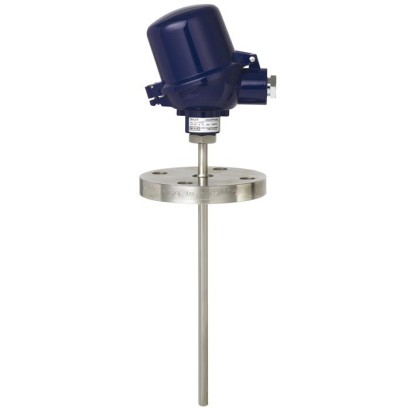
ترمومتر مقاومة فلنجي
الوصف
تُصمَّم موازين/مقاومات قياس الحرارة (ثرمومترات المقاومة) لهذه السلسلة للتركيب داخل الخزانات وخطوط الأنابيب. تتوفر وصلات شفة قياسية وفق DIN EN أو ASME.
تُعد حساسات درجة الحرارة هذه مناسبة للسوائل والغازات تحت أحمال ميكانيكية متوسطة. أنبوب الحماية مُلحم بالكامل ومُبرغي في رأس التوصيل. تُعد أنابيب الحماية المصنوعة من الفولاذ المقاوم للصدأ مناسبة للظروف الكيميائية العادية. يُوصى بطلاء كخيار إضافي مع الوسائط الكيميائية شديدة العدوانية، أو بطلاء صلب مقاوم للتآكل للوسائط الكاشطة.
يمكن إزالة عنصر القياس القابل للتبديل دون إخراج الحساس بالكامل من المنشأة. يتيح ذلك إجراء الفحص أو مراقبة معدات القياس، أو عند الحاجة إلى الصيانة، استبدال العنصر بينما تكون المنشأة قيد التشغيل. يساعد اختيار الأطوال القياسية على تقصير أزمنة التسليم وإتاحة إمكانية تخزين قطع الغيار.
المزايا
- مدى المستشعر من -196 ... +600 °C [-320 ... +1,112 °F]
- مع أنبوب حماية مصنّع مدمج
- عنصر قياس مزود بنابض ضغط (قابل للاستبدال)
- تتوفر نسخ مقاومة للانفجار لعدة أنواع من الموافقات (انظر صفحة 2 من ورقة البيانات)
الأسئلة والأجوبة
ما هو نطاق القياس لهذا الترمومتر؟
يمكن لنطاقات الحساس أن تصل إلى -196 … +600 °C، وتتوفر نطاقات أخرى مثل -50 … +500 °C و-50 … +250 °C و-30 … +300 °C و0 … +150 °C حسب التكوين.
ما هي وصلات الشفة المتوفرة؟
تتوفر شِفّات قياسية وفق DIN EN أو ASME بأحجام DN 25 … DN 50 (1" … 2") وفئات ضغط من 150 lbs إلى 1500 lbs ومن PN6 إلى PN100، مع أسطح إحكام RF وRFSF وFF وRTJ وأشكال C وE وN وF.
هل يمكن استبدال عنصر القياس دون إيقاف المنشأة؟
نعم، العنصر مثبّت بنابض وقابل للاستبدال؛ يمكن سحبه وفحصه أو استبداله أثناء تشغيل المنشأة دون إخراج الحساس بالكامل.
ما هي وسائط القياس المناسبة؟
الترمومتر مناسب للسوائل والغازات تحت حمل ميكانيكي متوسط. أنابيب الحماية من الفولاذ المقاوم للصدأ تناسب الظروف الكيميائية العادية، مع خيار طلاء للوسائط شديدة العدوانية أو طلاء صلب مقاوم للتآكل للوسائط الكاشطة.
ما هي درجات الحرارة المحيطة المدعومة وحماية الدخول؟
يعمل في نطاق -40 … +80 °C محيطياً، وبدرجة حماية دخول IP65.
هل يتوفر اعتماد للمناطق الخطرة؟
نعم، تتوفر نسخ محمية ضد الانفجار بمعتمدات ATEX وIECEx وغيرها، بتصنيفات مثل II 1G Ex ia IIC T1 ... T6 Ga وII 2G Ex eb IIC T1 ... T6 Gb ونسخ غبار Ex ia IIIC حتى T125 °C.
ما هو مستوى السلامة الوظيفية؟
يدعم الجهاز مستوى السلامة SIL 2، وهو مناسب للتطبيقات ذات متطلبات السلامة الوظيفية.
ما الذي يميّز TR10-F عن طرازات أخرى؟
يتميّز TR10-F بوصلته الشفّية القياسية (DIN EN/ASME) وأنبوب حماية مُلحَم بالكامل وعنصر قياس قابل للاستبدال، ما يجعله مناسباً للتركيب في الخزانات وخطوط الأنابيب تحت حمل ميكانيكي متوسط.
اجمع TR10-F لمهمتك
يُبنى رقم المادة تلقائيًا. عند الشك — تواصل مع مهندس؛ سنساعدك حسب معطيات الخط.
- اعتماد كهربائيWithout
- نوع الحماية من الاشتعالWithout
- المنطقةWithout
- مستشعر1xPt100, 3-wire
- فئة دقة المستشعرClass B, IEC 60751
- نطاق درجة الحرارة للفئة المحددة-50...+250°C
- الرأس / الغطاءBSZ, Aluminum, ball shaped, flip-top
- دخول الكابلStandard cable gland for für A-/B-/J- heads
- حجم مقاس الخيط لمدخل الكابلM20 x 1.5
- مرسلWithout (terminal block)
- تفاصيل جهاز الإرسالWithout
- التوصيل بأنبوب الرقبةM24 x 1,5
- أنبوب الحمايةStraight, flange, form 2F DIN 43772
- مادة أنبوب الحمايةStainless steel 1.4571
- قطر أنبوب الحماية9x1 mm
- حجم الشفةEN 1092-1 DN 25
- تصنيف الضغط—
- وجه الشفة—
- طول الإدخال [A]—
- طول الرقبة [MH/N]65
- المتطلبات الميكانيكيةWithout
- تصميمات خاصة للغلاف الحراريWithout
- الشهاداتWithout
أكمل التهيئة
اختر جميع الخيارات لإرسال الطلب.
| الطراز | TR10-F |
| السلسلة | TR10 |
| النوع الفرعي | Resistance thermometer with protection tube |
| نطاق درجة الحرارة | −196…+600 °C · −50…+500 °C · −50…+250 °C · −100…+450 °C · −30…+300 °C · +0…+150 °C · −196…+450 °C |
| مستوى السلامة الوظيفية (SIL) | SIL 2 |
| وصلة العملية | DIN ENASME150 lbs300 lbs600 lbsRFRFSFFFRTJDN 25DN 40DN 501 inch1 ½ inch2 inch1,500 lbsDN 25 ... DN 501" ... 2"PN6PN10PN16PN25PN40PN64PN100900 lbs1500 lbsForm CForm EForm NForm F |
| درجة حرارة العملية | −196…+600 °C |
| إشارة الخرج | 4-20mA · HART |
| وصلة كهربائية | M20 x 1.5 or ½ NPT |
| مادة المجس | 1.4571, 316L |
| مادة جراب الحرارة | 1.4571, 316L, 2.4360, 2.4819, 2.4610, 3.7035, Tantalum |
| حرارة المحيط | −40…+80 °C |
| تصنيف IP | IP65 |
| الشهادات | CERoHSATEXIECExEACEx UkraineINMETROCCCKCs-KOSHAPESOGOSTMTSCHSBelGIMUkrSEPROUzstandardKazInMetrEMCNAMUR NE 024KazlnMetr |
| حماية الانفجار | II 1G Ex ia IIC T1 ... T6 GaII 1/2G Ex ia IIC T1 ... T6 Ga/GbII 2G Ex ia IIC T1 ... T6 GbII 1D Ex ia IIIC T125 ... T65 °C DaII 1/2D Ex ia IIIC T125 ... T65 °C Da/DbII 2D Ex ia IIIC T125 ... T65 °C DbII 2G Ex eb IIC T1 ... T6 GbII 3G Ex ec IIC T1 ... T6 Gc XII 2D Ex tb IIIC TX °C Db0Ex ia IIC T6 ... T1 Ga X1Ex ia IIC T6 ... T1 Gb X2Ex nA IIC T6 ... T1 Gc XEx iaD 20 T65/T95/T125°CII 3D Ex tc IIIC TX °C Dc XII 3G Ex nA IIC T1 ... T6 Gc XEx ia IIIC T80…T440 °C Da XEx ia IIC T3 ... T6 GaEx nA IIC T1 ~ T6 GcEx ia IIC T4 ... T6Ex ib IIC T4 ... T6Ex ia IIIC T125 ...T65 °C DbEx ia IIC T1 ~ T6 Ga/GbEx ic IIC T1 ~ T6 GcEx iaD 21 T65/T95/T125°CEx i Zone 0 gas II 1G Ex ia IIC T1 ...T6 GaEx i Zone 0 gas Ex ia IIC T4 ...T6Ex i Zone 0 gas Ex ia IIC T1 ...T6 GaEx i Zone 0 gas Ex ia IIC T1 ...T6 Ga/GbEx i Zone 0 gas Ex ia IIC T1 ...T6 GbEx ia IIC T1 ... T6 GaEx ia IIC T1 ... T6 Ga/GbEx ia IIIC T80...T440 °C Db XExiaIICT3...T6Ga/GbT65℃DaExiaIICT125...T65℃Da/DbExiaIICT1 ~~ T6GaExiaIICT1~~ T6GbExiaIICT1 ~~ T6Ga/GbExicIICT1~~ T6GcExiaD20T65/T95/T125℃ExiaD21T65/T95/T125℃ExiaD20/21T65/T95/T125℃ |
| نوع المستشعر | Pt100 |
| فئة المستشعر | A, B, AA |
| قطر المجس | 3 mm |
| جراب الحرارة | نعم |
| شكل جراب الحرارة | 2F, 3F |
| لغات ورقة البيانات | EN |
| Logo | Description | Country |
|---|---|---|
| EU declaration of conformity ■ EMCdirective 1) | European Union | |
| IECEx (option) - in conjunction with ATEX Hazardous areas | International | |
| Zone 21 dust Ex ia IIIC T125 ...T65 °C Db EAC (option) Hazardous areas - Ex i Zone 0 gas 0Ex ia IIC T6 ...T1 Ga X | Eurasian Economic Community | |
| - Ex n Zone 2 gas 2Ex nA IIC T6 ...T1 Gc X Ex Ukraine (option) Hazardous areas - Ex i Zone 0 gas II 1G Ex ia IIC T1 ...T6 Ga | Ukraine |
| Logo | Description | Country |
|---|---|---|
| INMETRO (option) Hazardous areas - Ex i Zone 0 gas Ex ia IIC T3 ...T6 Ga Zone 1 mounting to zone 0 gas Ex ia IIC T3 ...T6 Ga/Gb | Brazil | |
| Zone 21 mounting to zone 20 dust Ex ia IIIC T125 ...T65 °C Da/Db CCC (option) Hazardous areas - Ex i Zone 0 gas Ex ia IIC T1 ~ T6 Ga Zone 1 gas Ex ia IIC T1 ~ T6 Gb Zone 1 mounting to zone 0 gas Ex ia IIC T1 ~ T6 Ga/Gb Zone 2 gas Ex ic IIC T1 ~ T6 Gc Zone 20 dust Ex iaD 20 T65/T95/T125°C Zone 21 dust Ex iaD 21 T65/T95/T125°C | China | |
| KCs - KOSHA (option) Hazardous areas Ex i Zone 0 gas Ex ia IIC T4 ...T6 | South Korea | |
| - | PESO (option) Hazardous areas - Ex i Zone 0 gas Ex ia IIC T1 ...T6 Ga Zone 1 mounting to zone 0 gas Ex ia IIC T1 ...T6 Ga/Gb Zone 1 gas Ex ia IIC T1 ...T6 Gb | India |
| GOST (option) Metrology, measurement technology | Russia | |
| KazInMetr (option) Metrology, measurement technology | Kazakhstan | |
| - | MTSCHS (option) Permission for commissioning | Kazakhstan |
| BelGIM (option) Metrology, measurement technology | Belarus | |
| UkrSEPRO (option) Metrology, measurement technology | Ukraine | |
| Uzstandard (option) Metrology, measurement technology | Uzbekistan |
| Logo | Description |
|---|---|
| SIL 2 Functional safety (only in conjunction with model T32 temperature transmitter) | |
| NAMUR | NAMUR NE 024 Hazardous areas (Ex i) |
| Single elements | 1 x 2-wire 1 x 3-wire 1 x 4-wire |
|---|---|
| Dual elements | 2 x 2-wire 2 x 3-wire 2 x 4-wire 3) |
عرض الكل (20)
| Class | Sensor construction | |
|---|---|---|
| Wire-wound | Thin-film | |
| Class B | -196 ...+600 °C | -50 ...+500 °C |
| -196 ...+450 °C | -50 ...+250 °C | |
| Class A 4) | -100 ...+450 °C | -30 ...+300 °C |
| Class AA 4) | -50 ...+250 °C | 0 ... 150 °C |
| Model | Material | Cable entry thread size | Ingress protection (max.) 1) IEC/EN 60529 | Cap | Surface | Connection to neck tube |
|---|---|---|---|---|---|---|
| BS | Aluminium | M20 x 1.5 or½NPT 3) | IP65 4) | Flat cap with 2 screws | Blue, painted 5) | M24 x 1.5,½NPT |
| BSZ | Aluminium | M20 x 1.5 or½NPT 3) | IP65 4) | Spherical hinged cover with cylinder head screw | Blue, painted 5) | M24 x 1.5,½NPT |
| BSZ-H | Aluminium | M20 x 1.5 or½NPT 3) | IP65 4) | Raised hinged cover with cylinder head screw | Blue, painted 5) | M24 x 1.5,½NPT |
| BSZ-H (2x cable outlet) | Aluminium | 2 x M20 x 1.5 or 2x½NPT 3) | IP65 4) | Raised hinged cover with cylinder head screw | Blue, painted 5) | M24 x 1.5 |
| BSZ-H / DIH10 2) | Aluminium | M20 x 1.5 or½NPT 3) | IP65 | Raised hinged cover with cylinder head screw | Blue, painted 5) | M24 x 1.5,½NPT |
| BSS | Aluminium | M20 x 1.5 or½NPT 3) | IP65 | Spherical hinged cover with clamping lever | Blue, painted 5) | M24 x 1.5,½NPT |
| BSS-H | Aluminium | M20 x 1.5 or½NPT 3) | IP65 | Raised hinged cover with clamping lever | Blue, painted 5) | M24 x 1.5,½NPT |
| BVS | Stainless steel | M20 x 1.5 3) | IP65 | Precision-cast screw-on lid | Blank, electropolished | M24 x 1.5 |
| BSZ-K | Plastic | M20 x 1.5 or½NPT 3) | IP65 | Spherical hinged cover with cylinder head screw | Black | M24 x 1.5 |
| BSZ-HK | Plastic | M20 x 1.5 or½NPT 3) | IP65 | Raised hinged cover with cylinder head screw | Black | M24 x 1.5 |
| Model | Explosion protection | |||||
|---|---|---|---|---|---|---|
| without | Ex i (gas) Zone 0, 1, 2 | Ex i (dust) Zone 20, 21, 22 | Ex e (gas) Zone 1, 2 | Ex t (dust) Zone 21, 22 | Ex nA (gas) Zone 2 | |
| BS | x | x | x | - | - | - |
| BSZ | x | x | x | x 6) | x 6) | x 7) |
| BSZ-H | x | x | x | x 6) | x 6) | x 7) |
| BSZ-H (2x cable outlet) | x | x | x | x 6) | x 6) | x 7) |
| BSZ-H / DIH10 1) | x | x | - | - | - | - |
| BSS | x | x | - | - | - | - |
| BSS-H | x | x | - | - | - | - |
| BVS | x | x | - | - | - | - |
| BSZ-K | x | x | - | - | - | - |
| BSZ-HK | x | x | - | - | - | - |
| Model | Material | Cable entry thread size | Ingress protection (max.) 1) IEC/EN 60529 | Cover / Cap | Surface | Connection to neck tube |
|---|---|---|---|---|---|---|
| KN4-A | Aluminium | ½NPTor M20 x 1.5 2) | IP65 | Screw-on lid | Blue, painted 3) | M24 x 1.5,½NPT |
| KN4-P 4) | Polypropylene | ½NPT | IP65 | Screw-on lid | White | ½NPT |
| Model | Explosion protection | |||||
|---|---|---|---|---|---|---|
| without | Ex i (gas) Zone 0, 1, 2 | Ex i (dust) Zone 20, 21, 22 | Ex e (gas) Zone 1, 2 | Ex t (dust) Zone 21, 22 | Ex nA (gas) Zone 2 | |
| KN4-A | x | x | - | - | - | - |
| KN4-P 4) | x | - | - | - | - | - |
| Cable entry | Cable entry thread size | Min./max. ambient temperature |
|---|---|---|
| Standard cable entry 1) | M20 x 1.5 or½NPT | -40 ...+80 °C |
| Plastic cable gland (cable Ø 6 ... 10 mm) 1) | M20 x 1.5 or½NPT | -40 ...+80 °C |
| Plastic cable gland (cable Ø 6 ... 10 mm), Ex e 1) | M20 x 1.5 or½NPT | -20 ...+80 °C (standard) -40 ...+70 °C (option) |
| Nickel-plated brass cable gland (cable Ø 6 ... 12 mm) | M20 x 1.5 or½NPT | -40 ...+80 °C |
| Stainless steel cable gland (cable Ø 7 ... 12 mm) | M20 x 1.5 or½NPT | -40 ...+80 °C |
| Plain threaded | M20 x 1.5 or½NPT | - |
| 2 x M20 x 1.5 2) | 2 x M20 x 1.5 | - |
| Junction box M12 x 1 (4-pin) 3) | M20 x 1.5 | -40 ...+80 °C |
| Sealing plugs for transport | M20 x 1.5 or½NPT | -40 ...+80 °C |
| Cable entry | Colour | Ingress protection (max.) 4) IEC/EN 60529 | Explosion protection | |||||
|---|---|---|---|---|---|---|---|---|
| without | Ex i (gas) Zone 0, 1, 2 | Ex i (dust) Zone 20, 21, 22 | Ex e (gas) Zone 1, 2 | Ex t (dust) Zone 21, 22 | Ex nA (gas) Zone 2 | |||
| Standard cable entry 1) | Blank | IP65 | x | x | - | - | - | - |
| Plastic cable gland 1) | Black or grey | IP66 5) | x | x | - | - | - | - |
| Plastic cable gland, Ex e 1) | Light blue | IP66 5) | x | x | x | - | - | - |
| Plastic cable gland, Ex e 1) | Black | IP66 5) | x | x | x | x | x | x |
| Nickel-plated brass cable gland | Blank | IP66 5) | x | x | x | - | - | - |
| Nickel-plated brass cable gland, Ex e | Blank | IP66 5) | x | x | x | x | x | x |
| Stainless steel cable gland | Blank | IP66 5) | x | x | x | - | - | - |
| Stainless steel cable gland, Ex e | Blank | IP66 5) | x | x | x | x | x | x |
| Plain threaded | - | IP00 | x | x | x 7) | x 7) | x 7) | x 7) |
| 2 x M20 x 1.5 2) | - | IP00 | x | x | x 7) | x 7) | x 7) | x 7) |
| Junction box M12 x 1 (4-pin) 3) | - | IP65 | x | x 6) | x 6) | - | - | - |
| Sealing plugs for transport | Transparent | - | not applicable, transport protection |
| First index number | Degree of protection / short description | Test parameter |
|---|---|---|
| 5 | Dust-protected | per IEC/EN 60529 |
| 6 | Dust-tight | per IEC/EN 60529 |
| Second index number | Degree of protection / short description | Test parameter |
|---|---|---|
| 4 | Protected against splash water | per IEC/EN 60529 |
| 5 | Protected against water jets | per IEC/EN 60529 |
| 6 | Protected against strong water jets | per IEC/EN 60529 |
| 7 1) | Protected against the effects of temporary immersion in water | per IEC/EN 60529 |
| 8 1) | Protected against the effects of continuous immersion in water | by agreement |
| Transmitter (selectable versions) | Model T15 | Model T32 |
|---|---|---|
| Data sheet | TE 15.01 | TE 32.04 |
| Output | ||
| 4 ...20mA | x | x |
| HART ® protocol | - | x |
| Connection method | ||
| 1 x 2-wire, 3-wire or 4-wire | x | x |
| Measuring current | < 0.2mA | < 0.3mA |
| Explosion protection | Optional | Optional |
| Connection head | T15 | T32 |
|---|---|---|
| BS | ○ | - |
| BSZ, BSZ-K | ○ | ○ |
| BSZ-H, BSZ-HK | ● | ● |
| BSZ-H (2x cable outlet) | ● | ● |
| BSZ-H / DIH10 | ○ | ○ |
| BSS | ○ | ○ |
| BSS-H | ● | ● |
| BVS | ○ | ○ |
| KN4-A / KN4-P | ○ | ○ |
| Protection tube | Material | Protection tube∅ | Suitable for measuring insert∅ | Connection to head |
|---|---|---|---|---|
| Straight, form 2F DIN 43772 | Stainless steel 1.4571 | 9x1mm 11x2mm 12 x 2.5mm 14 x 2.5mm | 6mm 6 mmwith sleeveØ8mm/ 8mm | M24 x 1.5 (rotatable threaded connection, male nut) |
| Tapered, form 3F DIN 43772 | Stainless steel 1.4571 | 12 x 2.5 mm, tapered to9mm | 6mm |
| Protection tube | Material | Protection tube∅ | Suitable for measuring insert∅ | Connection to head |
|---|---|---|---|---|
| Tapered, weld-on solid tip, in line with DIN 43772, non-standard design | Stainless steel 1.4571 | 9 x 1 mm, tapered to6mm 11 x 2 mm, tapered to6mm 12 x 2.5 mm, tapered to6mm | 3mm | M24 x 1.5 (rotatable threaded connection, male nut) |
| Protection tube | Material | Protection tube ∅ | Suitable for measuring insert∅ | Connection to head |
|---|---|---|---|---|
| Straight, in line with form 2F DIN 43772, non-standard design | 2.4360 (Monel400) / stainless steel 2.4819 (Hastelloy C276) / stainless steel 2.4610 (Hastelloy C4) / stainless steel 3.7035 (Titan Grade 2) / stainless steel | 13.7 x 2.2mm | 6 mmwith sleeveØ8mm/ 8mm | M24 x 1.5 (rotatable threaded connection, male nut) |
| Protection tube | Material | Protection tube∅ | Suitable for measuring insert∅ | Connection to head |
|---|---|---|---|---|
| Straight, in line with form 2F DIN 43772, non-standard design | Tantalum / stainless steel | 11 x 2 mm, tantalum cover 12 x 0.4mm 15 x 3 mm, tantalum cover 16 x 0.4mm | 6mm 6 mmwith sleeveØ8mm/ 8mm | M24 x 1.5 (rotatable threaded connection, male nut) |
| Tapered, in line with form 3F DIN 43772, non-standard design | Tantalum / stainless steel | 12 x 2.5 mm, tantalum cover 13 x 0.4mm | 6mm |
| Flange nominal width | Rating | Sealing face | Protection tube diameter | |
|---|---|---|---|---|
| 9x1mm | 11x2mm 12 x 2.5mm 14 x 2.5mm | |||
| EN 1092-1, DN 25 EN 1092-1, DN 40 | PN 6 | Form B1 | x | x |
| Form B2 | x | x | ||
| Form C (tongue) | x | x | ||
| Form D (groove) | x | x | ||
| PN 10 ... 40 | Form B1 | x | x | |
| Form B2 | x | x | ||
| Form C (tongue) | x | x | ||
| Form D (groove) | x | x | ||
| PN 63 ... 100 | Form B1 | - | x | |
| Form B2 | - | x | ||
| Form C (tongue) | - | x | ||
| Form D (groove) | - | x | ||
| EN 1092-1, DN 50 | PN 6 | Form B1 | x | x |
| Form B2 | x | x | ||
| Form C (tongue) | x | x | ||
| Form D (groove) | x | x | ||
| PN 10 ... 16 | Form B1 | x | x | |
| Form B2 | x | x | ||
| Form C (tongue) | x | x | ||
| Form D (groove) | x | x | ||
| PN 25 ... 40 | Form B1 | x | x | |
| Form B2 | x | x | ||
| Form C (tongue) | x | x | ||
| Form D (groove) | x | x | ||
| PN 63 | Form B1 | - | x | |
| Form B2 | - | x | ||
| Form C (tongue) | - | x | ||
| Form D (groove) | - | x | ||
| PN 100 | Form B1 | - | x | |
| Form B2 | - | x | ||
| Form C (tongue) | - | x | ||
| Form D (groove) | - | x | ||
| DIN 2526/2527, DN 25 DIN 2526/2527, DN 40 | PN 6 | Form C | x | x |
| Form E | x | x | ||
| Form N (groove) | x | x | ||
| Form F (tongue) | x | x | ||
| PN 10 ... 16 | Form E | x | x | |
| Form N (groove) | x | x | ||
| Form F (tongue) | x | x | ||
| PN 25 ... 40 | Form C | x | x | |
| x | x | |||
| Form E Form N (groove) | x | x | ||
| Form F (tongue) | x | x |
لم تجد الإجابة في الوثائق؟ سيرد المهندس خلال يوم عمل.
اسأل المهندس →48 مادة قياسية من عائلة TR10
إذا كنت تعرف الرمز — اختر مباشرة. إذا لا — استخدم المُهيِّئ في الوضع «01».