
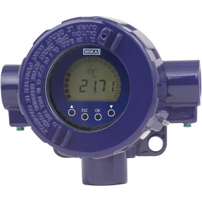
مرسل درجة حرارة ميداني HART ®
الوصف
مرسلات درجة الحرارة الميدانية من سلسلة TIF، والتي تتكوّن من هيكل ميداني متين، ومرسل درجة الحرارة طراز T32، وشاشة طراز DIH، صُممت للاستخدام العام في هندسة العمليات.
توفّر دقة عالية، وعزلًا جلفانيًا، وحماية ممتازة ضد التأثيرات الكهرومغناطيسية (EMI). عبر بروتوكول HART ® يمكن تهيئة TIFxx (قابل للتشغيل البيني) باستخدام مجموعة متنوعة من أدوات التهيئة المفتوحة.
بالإضافة إلى أنواع الحساسات المختلفة، مثل الحساسات وفقًا لـ DIN EN 60751 وJIS C1606 وDIN 43760 وIEC 60584 أو DIN 43710، يمكن أيضًا تحديد خصائص حساسات مخصصة للعميل، وذلك عبر إدخال أزواج قيم (خطية مُعرّفة من المستخدم). ومن خلال تهيئة حسّاس مع تكرار (حساس مزدوج)، ففي حال تعطل أحد الحساسات سيتحوّل تلقائيًا إلى الحساس العامل.
علاوة على ذلك، توجد إمكانية تفعيل اكتشاف انحراف الحساس. عندئذٍ يحدث إشارة خطأ عندما تتجاوز قيمة فرق درجة الحرارة بين الحساس 1 والحساس 2 قيمة يمكن للمستخدم تحديدها.
للموافقات الإضافية، راجع الصفحة 10
مرسلات درجة الحرارة الميدانية طرازي TIF50 وTIF52
كما يتمتع مرسل درجة الحرارة الميداني بوظائف إشرافية متقدمة إضافية مثل مراقبة مقاومة توصيل الحساس واكتشاف انقطاع الحساس وفقًا لـ NAMUR NE89، بالإضافة إلى مراقبة مجال القياس. علاوة على ذلك، تتميز هذه المرسلات بوظيفة مراقبة ذاتية دورية شاملة.
عبر الشاشة يمكن عرض إنذارات المجال وكذلك قيم MIN وMAX.
يتوفر مرسل درجة الحرارة الميداني في عدة طرازات لهياكل ميدانية. ويمكن تحديد الفولاذ المقاوم للصدأ والألومنيوم.
يمكن تركيبه مباشرة على الحائط. كما يتوفر طقم تركيب على الأنابيب للتركيب على الأنابيب ذات قطر 1 ... 2".
المزايا
- إمكانية ضبط الوحدات ونطاق القياس في الموقع (طراز TIF52 فقط)
- موافقات مختلفة للمناطق الخطرة
- مستشعر مزدوج، إمكانية القياس المكرر
- منحنيات مميزة قابلة للبرمجة حسب طلب العميل
الأسئلة والأجوبة
ما هو نطاق قياس درجة الحرارة لهذا المرسل؟
يعتمد نطاق القياس على نوع الحساس المستخدم؛ فالنطاقات المتاحة تمتد من -270 °C حتى +1820 °C حسب الحساس (ثيرمومقاومة أو ثيرموكوبل).
ما مدى دقة القياس؟
الدقة ±0.03 % of measuring span.
ما هي إشارة الخرج وطريقة التوصيل؟
خرج 4 … 20 mA مع بروتوكول HART®، وتوصيل كهربائي بسلكين (2-wire)، وتغذية 14.5 ... 42 V DC.
هل يمكن استخدامه في المناطق الخطرة؟
نعم، يتوفر مع موافقات ATEX وIECEx، ومن أمثلة تصنيفات الانفجار: II 2G Ex db IIC T4/T5/T6 Gb وEx ia [ia Ga] IIC T4/T5/T6 Gb وDIP A20 Ta 120 °C.
ما الفرق بين الطرازين TIF50 وTIF52؟
في الطراز TIF52 فقط يمكن ضبط الوحدات ونطاق القياس مباشرةً على الموقع، بينما لا تتوفر هذه الإمكانية في TIF50.
ما أنواع الحساسات المدعومة؟
يدعم المرسل Pt100 وPt(x) وJPt100 وNi100، والثيرموكوبلات من الأنواع J وK وL وE وN وT وU وR وS وB، بالإضافة إلى حساس mV.
ما هي درجة الحماية من الغبار والماء؟
درجة الحماية IP66، ويمكن تشغيل الجهاز ضمن نطاق درجة حرارة محيط من -60 … +85 °C.
كيف يتم تركيب المرسل؟
يتوفر الهيكل بأشكال مختلفة من الفولاذ المقاوم للصدأ أو الألومنيوم، ويمكن تركيبه مباشرةً على الحائط أو باستخدام طقم تركيب على الأنابيب ذات قطر 1 ... 2".
| الطراز | TIF50, TIF52 |
| السلسلة | TIF |
| النوع الفرعي | Field temperature transmitter |
| نطاق درجة الحرارة | −200…+850 °C · −270…+1300 °C · −200…+500 °C · −60…+250 °C · −210…+1200 °C · −200…+900 °C · −270…+1000 °C · −270…+400 °C · −200…+600 °C · −50…+1768 °C · +0…+1820 °C |
| فئة الدقة | ±0.03 % of measuring span |
| إشارة الخرج | HART · 4-20mA |
| التغذية | 14.5 ... 42 V DC |
| وصلة كهربائية | 2-wire |
| حرارة المحيط | −60…+85 °C |
| تصنيف IP | IP66 |
| الوزن | 1.5 kg |
| الشهادات | CERoHSEACATEXIECExREACH |
| حماية الانفجار | II 2G Ex db IIC T4/T5/T6 GbEx ia [ia Ga] IIC T4/T5/T6 GbEx ia IIIC T135 °C Db1 Ex d IIC T6 ... T40 Ex ia IIC T4/T5/T61 Ex ib [ia ] IIC T4/T5/T6DIP A20 Ta 120 °CDIP A21 Ta 120 °CATEXIECExEx d IIC T6...T4II(1)2G Ex ia[ia Ga]IIC T4/T5/T6 GbII 2D Ex ia IIC T135℃ DbDIP A20 Ta 120℃DIP A21 Ta 120℃ |
| نوع المستشعر | Pt100, Pt(x), JPt100, Ni100, Type J, K, L, E, N, T, U, R, S, B, mV sensor |
| فئة المستشعر | IEC 60751:2008, JIS C1606:1989, DIN 43760:1987, DIN 43710:1985 |
| لغات ورقة البيانات | EN, DE |
| Field temperature | Max. configurable measuring range 1) | Standard | α values | Minimum measuring span 14) | Typical measuring deviation 2) | Temperature coefficient per °C typical 3) | |
|---|---|---|---|---|---|---|---|
| Resistance sensor | Pt100 | -200 ...+850 °C | IEC 60751 :2008 | α = 0.00385 | 10 K or 3.8Ω (greater value applies) | ≤ ±0.12 °C 5) | ≤ ±0.0094 °C 6) 7) |
| Pt(x) 4) 10 ... 1000 | -200 ...+850 °C | IEC 60751:2008 | α = 0.00385 | ≤ ±0.12 °C 5) | ≤ ±0.0094 °C 6) 7) | ||
| JPt100 | -200 ...+500 °C | JIS C1606: 1989 | α = 0.003916 | ≤ ±0.12 °C 5) | ≤ ±0.0094 °C 6) 7) | ||
| Ni100 | -60 ...+250 °C | DIN 43760: 1987 | α = 0.00618 | ≤ ±0.12 °C 5) | ≤ ±0.0094 °C 6) 7) | ||
| Resistance sensor | 0 ...8,370Ω | 4Ω | ≤ ±1.68Ω 8) | ≤ ±0.1584Ω 8) | |||
| Potentiometer 9) | 0 ...100% | 10% | ≤ 0.50% 10) | ≤ ±0.0100% 10) | |||
| Measuring current during measurement | Max. 0.3 mA(Pt100) | ||||||
| Connection methods | 1 sensor 2-/4-/3-wire or 2 sensors 2-wire (for further information, please refer to 'Designation of connection terminals') | ||||||
| Max. lead resistance | 50 Ωeach wire, 3-/4-wire | ||||||
| Thermo - couple | Type J (Fe-CuNi) | -210 ... +1,200 °C | IEC 60584-1: 1995 | 50 K or2mV (greater value applies) | ≤ ±0.91 °C 11) | ≤ ±0.0217 °C 7) 11) | |
| Type K (NiCr-Ni) | -270 ... +1,300 °C | IEC 60584-1: 1995 | ≤ ±0.98 °C 11) | ≤ ±0.0238 °C 7) 11) | |||
| Type L (Fe-CuNi) | -200 ...+900 °C | DIN 43760: 1987 | ≤ ±0.91 °C 11) | ≤ ±0.0203 °C 7) 11) | |||
| Type E (NiCr-Cu) | -270 ... +1,000 °C | IEC 60584-1: 1995 | ≤ ±0.91 °C 11) | ≤ ±0.0224 °C 7) 11) | |||
| Type N (NiCrSi-NiSi) | -270 ... +1,300 °C | IEC 60584-1: 1995 | ≤ ±1.02 °C 11) | ≤ ±0.0238 °C 7) 11) | |||
| TypeT (Cu-CuNi) | -270 ...+400 °C | IEC 60584-1: 1995 | ≤ ±0.92 °C 11) | ≤ ±0.0191 °C 7) 11) | |||
| Type U (Cu-CuNi) | -200 ...+600 °C | DIN 43710: 1985 | ≤ ±0.92 °C 11) | ≤ ±0.0191 °C 7) 11) | |||
| Type R (PtRh-Pt) | -50 ... +1,768 °C | IEC 60584-1: 1995 | 150 K | ≤ ±1.66 °C 11) | ≤ ±0.0338 °C 7) 11) | ||
| Type S (PtRh-Pt) | -50 ... +1,768 °C | IEC 60584-1: 1995 | 150 K | ≤ ±1.66 °C 11) | ≤ ±0.0338 °C 7) 11) | ||
| Type B (PtRh-Pt) | 0 ... +1,820 °C 15) | IEC 60584-1: 1995 | 200 K | ≤ ±1.73 °C 11) | ≤ ±0.0500 °C 7) 12) | ||
| mVsensor | -500 ...+1,800mV | 4mV | ≤ ±0.33mV 13) | ≤ ±0.0311mV 7) 13) | |||
| Connection methods | 1 sensor or 2 sensors (for further information, please refer to 'Designation of connection terminals') | ||||||
| Max. lead resistance | 5 kΩ each wire | ||||||
| Cold junction compensation, configurable | internal compensation or external with Pt100, with thermostat or off |
| Display, operating unit | Model TIF50 | Model TIF52 |
|---|---|---|
| Display principle | LCD, rotatable in 10° steps | |
| Measured value of display | 7-segment LCD, 5-digit, character size9mm | |
| Bar graph | 20-segment LCD | |
| Info line | 14-segment LCD, 6-digit, character size 5.5mm | |
| Status indicators | ♥ :HART ® mode (signalling of HART ® parameter adoption) : Unit lock :Warnings or error messages | |
| Indication range | -9999 ... 99999 | |
| Measuring rate | approx. 4/s | |
| Accuracy | ±0.1 %of measuring span | ±0.05 %of measuring span |
| Temperature coefficient | ±0.1 %of measuring span / 10 K | |
| HART ® functionality | ||
| ■ Access control | - | Secondary master |
| ■ Automatically set parameters | ||
| ■ Available commands | - | Unit, measuring range start/end, format, zero point, span, damping, polling address |
| ■ Identified commands | Generic mode: 1, 15, 35, 44 | Generic mode: 0, 1, 6, 15, 34, 35, 36, 37, 44 |
| ■ Multidrop | Not supported | Measured values are automatically taken from the HART ® digital data and displayed |
| Rise time t 90 | Approx. 0.8 s |
|---|---|
| Damping , configurable | Off ; configurable between 1 s and 60 s |
| Switch-on time (time to get the first measured value) | Max. 15 s |
| Measuring rate 1) | Measured value update approx. 3/s |
| Analogue output , configurable | Linear to temperature per IEC 60751 / JIS C1606 / DIN 43760 (for resistance sensors) or linear to temperature per IEC 584 / DIN 43710 (for thermocouples) 4 ... 20 mAor 20 ... 4 mA, 2-wire | |
|---|---|---|
| Output limits , configurable per NAMUR NE43 customer-specifically adjustable | Lower limit 3.8 mA 3.6 ...4.0mA | upper limit 20.5 mA 20.0 ...21.5mA |
| Current value for signalling, configurable per NAMUR NE43 Substitute value | Downscale < 3.6 mA (3.5 mA) 3.5 ...12.0mA | upscale > 21.0 mA(21.5 mA) 12.0 ...23.0mA |
| In simulation mode, independent from input signal, simulation value configurable from 3.5 ...23.0mA | ||
| Load R A (without HART ® ) | R A ≤ (U B - 13.5 V) / 0.023 A with R A in Ωand U B inV | |
| Load R A (with HART ® ) | R A ≤ (U B - 14.5 V) / 0.023 A with R A in Ωand U B inV | |
| Insulation voltage (input to analogue output) | AC 1,200V (50 Hz / 60 Hz); 1 s | |
| Insulation specification to DIN EN 60664-1:2003 | Overvoltage category III |
عرض الكل (15)
| Model | Approvals | Permissible ambient/storage temperature (in accordance with the relevant temperature | Safety-related maximum values | Power supply U B (DC) | |
|---|---|---|---|---|---|
| classes) | Sensor (Connections 1 - 4) | Current loop (Connections ±) | |||
| TIF50-S, TIF52-S | without | {-50} -40 ...+85 °C | - | - | 14.5 ...42V |
| TIF50-F, TIF52-F | Flameproof enclosure BVS 10 ATEX E 158 IECEx BVS 10.0103 II 2G Ex db IIC T4/T5/T6 Gb | -40 ...+85 °C at T4 -40 ...+75 °C at T5 -40 ...+60 °C at T6 | - | U M = 30V P M =2W | 14.5 ...30V |
| Ex db IIC T4/T5/T6 Gb | |||||
| TIF50-F, TIF52-F | Flameproof enclosure TC RU C-DE.BH02.B.00466/20 1 Ex d IIC T6 ...T4 | -60 2) / -40 ...+85 °C at T4 -60 2) / -40 ...+75 °C at T5 -60 2) / -40 ...+60 °C at T6 | - | U M = 30V P M =2W | 14.5 ...30V |
| TIF50-I, TIF52-I | Intrinsically safe equipment 1) BVS 16 ATEX E 112 X IECEx BVS 16.0075X | see installation drawing in the operating instructions at | see installation drawing in the operating instructions at | 14.5 ...29V | |
| II (1)2G II 2G Ex ia [ia Ga] IIC T4/T5/T6 Gb Ex ia IIC T4/T5/T6 Gb | -40 ...+85 °C at T4 -40 ...+70 °C at T5 -40 ...+55 °C at T6 | www.wika.com | www.wika.com | ||
| II (1)2D II 2D Ex ia [ia Da] IIIC T135 °C Db Ex ia IIIC T135 °C Db | -40 ...+40 °C (P i = 680 mW) -40 ...+70 °C (P i = 650 mW) | ||||
| TIF50-I, TIF52-I | Intrinsically safe equipment 1) TC RU C-DE.AЯ45.B.00918 | see installation drawing in | see installation drawing in | 14.5 ...29V | |
| 0 Ex ia IIC T4/T5/T6 1 Ex ib [ia ] IIC T4/T5/T6 | -60 2) / -40 ...+85 °C at T4 -60 2) / -40 ...+70 °C at T5 -60 2) / -40 ...+55 °C at T6 | the operating instructions at www.wika.com | the operating instructions at www.wika.com | ||
| DIP A20Ta 120 °C DIP A21Ta 120 °C | -60 2) / -40 ...+40 °C (P i = 680 mW) -60 2) / -40 ...+70 °C (P i = 650 mW) |
| Not measurable | |||
|---|---|---|---|
| Power supply effect | Not measurable | ||
| Warm-up time | After approx. 5 minutes the instrument will function to the specifications (accuracy) | ||
| Input | Measuring deviation per DIN EN 60770, 23 °C ±3 K | Mean temperature coefficient (TC) for each 10 K change in ambient temperature in the range -40 ... +85 °C Lead resistance effects | Long-term stability after 1 year |
| ■ Resistance thermometer Pt100/JPt100/ Ni100 1) | -200 °C ≤ MV≤200 °C: ±0.10 K MV>200 °C: ±(0.1 K + 0.01 %|MW-200 K|) 2) | ±(0.06 K + 0.015%MV) 4-wire: no effect (0 to 50 Ωeach wire) 3-wire: ±0.02 Ω/ 10Ω 50 Ωeach wire) | ±60 mΩor 0.05 %of MV, greater value applies |
| ■ Resistance sensor | ≤ 890 Ω: 0.053Ω 4) or 0.015%MV 5) ≤ 2,140 Ω: 0.128Ω 4) or 0.015%MV 5) ≤ 4,390 Ω: 0.263Ω 4) or 0.015%MV 5) ≤ 8,380 Ω: 0.503Ω 4) or 0.015%MV 5) | (0 to 2-wire: Resistor of the ±(0.01 Ω+0.01%MV) | |
| ■ Potentiometer | R part /R total is max.±0.5% | ±(0.1%MV) | |
| ■ Thermocouples Type E, J | -150 °C < MV<0°C: ±(0.3 K + 0.2 %|MV|) MV>0°C: ±(0.3 K + 0.03%MV) | Type E: MV>-150 °C: ±(0.1 K + 0.015 %|MV|) Type J: MV>-150 °C: ±(0.07 K + 0.02 %|MV|) 6 µV / 1,000Ω 6) | ±20 µV or 0.05 %of MV, greater value applies |
| Type T, U | -150 °C < MV<0°C: ±(0.4 K + 0.2 %|MV|) MV>0°C: ±(0.4 K + 0.01%MV) | -150 °C < MV<0°C: ±(0.07 K + 0.04%MV) MV>0°C: ±(0.07 K + 0.01%MV) | |
| Type R, S | 50 °C < MV<400 °C: ±(1.45 K + 0.12 %|MV - 400 K|) 400 °C < MV<1,600 °C: ±(1.45 K + 0.01 %|MV - 400 K|) | Type R: 50 °C < MV<1,600 °C: ±(0.3 K + 0.01 %|MV- 400 K|) Type S: 50 °C < MV<1,600 °C: ±(0.3 K + 0.015 %|MV- 400 K|) | |
| Type B | 450 °C < MV<1,000 °C: ±(1.7 K + 0.2 %|MV - 1,000 K|) MV>1,000 °C: ±1.7 K | 450 °C < MV<1,000 °C: ±(0.4 K + 0.02 %|MV - 1,000 K|) MV>1,000 °C: ±(0.4 K + 0.005 %(MV- 1,000 K)) | |
| Type K | -150 °C < MV<0°C: ±(0.4 K + 0.2 %|MV|) 0 °C < MV<1,300 °C: | -150 °C < MV<1,300 °C: ±(0.1 K + 0.02 %|MV|) | |
| Type L | -150 °C < MV<0°C: ±(0.3 K + 0.1 %|MV|) MV>0°C:±(0.3 K + 0.03%MV) | -150 °C < MV<0°C: ±(0.07 K + 0.02 %|MV|) MV>0°C:±(0.07 K + 0.015%MV) | |
| Type N | -150 °C < MV<0°C: ±(0.5 K + 0.2 %|MV|) MV>0°C:±(0.5 K + 0.03%MV) | -150 °C < MV<0°C: ±(0.1 K + 0.05 %|MV|) MV>0°C:±(0.1 K + 0.02%MV) | |
| ■ mVsensor | ≤1,160 mV: 10 μV + 0.03 %|MV| >1,160 mV: 15 μV + 0.07% |MV| | 2 μV + 0.02 %|MV| 100 μV + 0.08 %|MV| | |
| ■ Cold junction 7) | ±0.8 K | ±0.1 K | ±0.2 K |
| Output | ±0.03 %of measuring span | ±0.03 %of measuring span | ±0.05 %of span |
| Input Pt100, MV<200 °C | ±0.100 K |
|---|---|
| Output ±(0.03 %of 150 K) | ±0.045 K |
| TC 10 K - input ±(0.06 K + 0.015 %of 150 K) | ±0.083 K |
| TC 10 K - output ±(0.03 %of 150 K) | ±0.045 K |
| Measuring deviation (typical) √input² + output² +TC input ² +TC output ² | ±0.145 K |
| Measuring deviation (maximum) (input + output +TC input +TC output ) | ±0.273 K |
| Input type K, 0 °C < MV<1,300 °C ±(0.4 K + 0.04 %of 400 K) | ±0.56 K |
|---|---|
| Cold junction ±0.8 K | ±0.80 K |
| Output ±(0.03 %of 400 K) | ±0.12 K |
| Measuring deviation (typical) √input² + cold junction² + output² | ±0.98 K |
| Measuring deviation (maximum) (input + cold junction + output) | ±1.48 K |
| Test current for sensor monitoring 1) | Nom.20 µA during test cycle, otherwise 0 µA |
|---|---|
| Monitoring NAMUR NE89 (monitoring of input lead resistance) | |
| ■ Resistance thermometer (Pt100, 4-wire) | R L1 + R L4 > 100 Ωwith hysteresis5Ω R L2 + R L3 > 100 Ωwith hysteresis5Ω |
| ■ Thermocouple | R L1 + R L4 + R thermocouple > 10 kΩ with hysteresis 100Ω |
| Sensor break monitoring | Always active |
| Self-monitoring | Active permanently, e.g.RAM/ROM test, logical program operating checks and validity check |
| Measuring range monitoring | Monitoring of the set measuring range for upper/lower deviations Standard: Deactivated |
| Monitoring of input lead resistance (3-wire) | Monitoring of the resistance difference between lead 3 and 4; an error will be indicated if there is a difference of > 0.5 Ωbetween leads 3 and 4 |
| Material | ■ Aluminium, window from polycarbonate ■ Stainless steel, window from polycarbonate | |
|---|---|---|
| Colour | Aluminium: Night blue, RAL 5022 | Stainless steel: Silver |
| Cable bushings | 3 x M20 x 1.5 or3x½NPT | |
| Ingress protection | IP66 | |
| Weight | Aluminium: approx. 1.5 kg | Stainless steel: approx. 3.7 kg |
| Dimensions | See drawing |
| Ambient temperature | -60 1) / -40 ...+85 °C |
|---|---|
| Functional area of the display | -20 2) ...+70 °C |
| Climate class per IEC 654-1: 1993 | Cx (-20 ...+85 °C, 35 ... 85 %r.h., non-condensing) |
| Maximum permissible humidity | 93 %r.h.±3% |
| Vibration resistance per IEC 60068-2-6:2007 | 3 g |
| Shock resistance per IEC 68-2-27: 1987 | 30 g |
| Electromagnetic compatibility (EMC) | EN 61326 emission (group 1, class B) and interference immunity (industrial application), and also NAMUR NE21 |
| Model | Description | Order number |
|---|---|---|
| Programming unit, model PU-H | ||
| VIATOR ® HART ® USB | HART ® modem for USB interface | 11025166 |
| VIATOR ® HART ® USB PowerXpress™ | HART ® modem for USB interface | 14133234 |
| VIATOR ® HART ® RS-232 | HART ® modem for RS-232 interface | 7957522 |
| VIATOR ® HART ® Bluetooth ® Ex | HART ® modem for Bluetooth interface, Ex | 11364254 |
| Magnetic quick connector magWIK | ■ Replacement for crocodile clips and HART ® terminals ■ Fast, safe and tight electrical connection ■ For all configuration and calibration processes | 14026893 |
| Logo | Description | Region |
|---|---|---|
| EU declaration of conformity | European Union | |
| EMCdirective EN 61326 emission (group 1, class B) and interference immunity (industrial application) |
| Logo | Description | Region |
|---|---|---|
| EU declaration of conformity | European Union | |
| ATEX directive Hazardous areas | ||
| IECEx Hazardous areas | International | |
| EAC | Eurasian Economic Community | |
| EMCdirective | ||
| Hazardous areas 1) | ||
| PAC Russia Metrology, measurement technology | Russia | |
| PAC Kazakhstan Metrology, measurement technology | Kazakhstan | |
| - | MChS Permission for commissioning | Kazakhstan |
| PAC Belarus Metrology, measurement technology | Belarus | |
| PAC Ukraine Metrology, measurement technology | Ukraine | |
| DNOP - MakNII | Ukraine | |
| Mining | ||
| Hazardous areas | ||
| - | PESO Hazardous areas | India |
| Certificates | ■ 2.2 test report |
|---|---|
| ■ 3.1 inspection certificate | |
| Calibration | ■ DAkkS calibration certificate |
لم تجد الإجابة في الوثائق؟ سيرد المهندس خلال يوم عمل.
اسأل المهندس →