
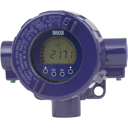
משדר טמפרטורת שדה HART ®
תיאור
משדרי טמפרטורת שדה מסדרת TIF, הכוללים בית שדה קשיח, משדר טמפרטורה מדגם T32 ותצוגה מדגם DIH, תוכננו לשימוש כללי בהנדסת תהליכים.
הם מציעים דיוק גבוה, בידוד גלוואני והגנה מצוינת מפני השפעות אלקטרומגנטיות (EMI). באמצעות פרוטוקול HART ® ניתן להגדיר את ה-TIFxx (תואם) עם מגוון כלי תצורה פתוחים.
בנוסף לסוגי החיישנים השונים, למשל חיישנים בהתאם ל-DIN EN 60751, JIS C1606, DIN 43760, IEC 60584 או DIN 43710, ניתן גם להגדיר מאפייני חיישן ייעודיים ללקוח באמצעות הזנת זוגות ערכים (ליניאריזציה מוגדרת על ידי המשתמש). באמצעות תצורת חיישן עם יתירות (חיישן כפול), במקרה של כשל בחיישן הוא יעבור באופן אוטומטי לחיישן העובד.
בנוסף, קיימת אפשרות להפעיל זיהוי סטיית חיישן. באמצעות זאת מתרחשת הודעת שגיאה כאשר גודל הפרש הטמפרטורה בין חיישן 1 לחיישן 2 עולה על ערך שניתן לבחור על ידי המשתמש.
לצורך אישורים נוספים ראו עמוד 10
משדרי טמפרטורת שדה דגמים TIF50, TIF52
למשדר טמפרטורת השדה יש גם פונקציות פיקוח מתקדמות נוספות, כגון ניטור התנגדות מוליכי החיישן וזיהוי שבירת חיישן בהתאם ל-NAMUR NE89 וכן ניטור טווח המדידה. בנוסף, למשדרים אלה יש פונקציית ניטור עצמי מחזורית מקיפה.
באמצעות התצוגה ניתן להציג אזעקות טווח וכן ערכי MIN ו-MAX.
משדר טמפרטורת השדה זמין במספר גרסאות של בית שדה. ניתן לבחור פלדת אל-חלד ואלומיניום.
ניתן להרכיב אותו ישירות על קיר. ערכת הרכבה לצנרת זמינה גם להתקנה על צינורות בקוטר של 1 ... 2".
תכונות מיוחדות
- הגדרת יחידות וטווח מדידה באתר (דגם TIF52 בלבד)
- אישורים שונים לאזורים מסוכנים
- חיישן דופלקס, מדידה משוכפלת (redundant) אפשרית
- עקומות אפיון ייחודיות ללקוח – ניתנות לתכנות
שאלות ותשובות
מהו טווח המדידה של המשדר?
המשדר תומך בטווחי מדידה התלויים בסוג החיישן, לדוגמה -200 ... 850 °C עבור Pt100, -270 ... 1300 °C עבור תרמוזוגת Type K, ועד 0 ... 1820 °C עבור Type B.
מהו הדיוק של המשדר?
הדיוק הוא ±0.03 % of measuring span.
אילו אישורי אזורים מסוכנים זמינים?
המשדר מאושר לפי ATEX ו-IECEx, בין היתר II 2G Ex db IIC T4/T5/T6 Gb, Ex ia [ia Ga] IIC T4/T5/T6 Gb, Ex d IIC T6...T4 ו-DIP A20/A21 Ta 120 °C.
מה ההבדל בין TIF50 ל-TIF52?
בדגם TIF52 ניתן להגדיר יחידות וטווח מדידה ישירות בשטח; ב-TIF50 יכולת זו אינה זמינה.
מהו אות הפלט וחיבור החשמל?
הפלט הוא 4 … 20 mA עם פרוטוקול HART®, בחיבור דו-חוטי (2-wire), עם אספקת חשמל 14.5 ... 42 V DC.
מהי דרגת ההגנה מפני חדירה?
דרגת ההגנה היא IP66.
באיזו טמפרטורת סביבה ניתן להפעיל את המשדר?
טווח טמפרטורת הסביבה הוא -60 ... +85 °C.
כיצד ניתן להרכיב את המשדר?
ניתן להרכיב אותו ישירות על קיר, או על צינור בקוטר 1 ... 2" באמצעות ערכת הרכבה לצנרת.
| דגם | TIF50, TIF52 |
| סדרה | TIF |
| תת-קטגוריה | Field temperature transmitter |
| טווח טמפרטורה | −200…+850 °C · −270…+1300 °C · −200…+500 °C · −60…+250 °C · −210…+1200 °C · −200…+900 °C · −270…+1000 °C · −270…+400 °C · −200…+600 °C · −50…+1768 °C · +0…+1820 °C |
| מחלקת דיוק | ±0.03 % of measuring span |
| אות יציאה | HART · 4-20mA |
| הזנה | 14.5 ... 42 V DC |
| חיבור חשמלי | 2-wire |
| טמפ׳ סביבה | −60…+85 °C |
| דרגת הגנה IP | IP66 |
| משקל | 1.5 kg |
| תקנים | CERoHSEACATEXIECExREACH |
| הגנת התפוצצות | II 2G Ex db IIC T4/T5/T6 GbEx ia [ia Ga] IIC T4/T5/T6 GbEx ia IIIC T135 °C Db1 Ex d IIC T6 ... T40 Ex ia IIC T4/T5/T61 Ex ib [ia ] IIC T4/T5/T6DIP A20 Ta 120 °CDIP A21 Ta 120 °CATEXIECExEx d IIC T6...T4II(1)2G Ex ia[ia Ga]IIC T4/T5/T6 GbII 2D Ex ia IIC T135℃ DbDIP A20 Ta 120℃DIP A21 Ta 120℃ |
| סוג חיישן | Pt100, Pt(x), JPt100, Ni100, Type J, K, L, E, N, T, U, R, S, B, mV sensor |
| מחלקת חיישן | IEC 60751:2008, JIS C1606:1989, DIN 43760:1987, DIN 43710:1985 |
| שפות גיליון נתונים | EN, DE |
| Field temperature | Max. configurable measuring range 1) | Standard | α values | Minimum measuring span 14) | Typical measuring deviation 2) | Temperature coefficient per °C typical 3) | |
|---|---|---|---|---|---|---|---|
| Resistance sensor | Pt100 | -200 ...+850 °C | IEC 60751 :2008 | α = 0.00385 | 10 K or 3.8Ω (greater value applies) | ≤ ±0.12 °C 5) | ≤ ±0.0094 °C 6) 7) |
| Pt(x) 4) 10 ... 1000 | -200 ...+850 °C | IEC 60751:2008 | α = 0.00385 | ≤ ±0.12 °C 5) | ≤ ±0.0094 °C 6) 7) | ||
| JPt100 | -200 ...+500 °C | JIS C1606: 1989 | α = 0.003916 | ≤ ±0.12 °C 5) | ≤ ±0.0094 °C 6) 7) | ||
| Ni100 | -60 ...+250 °C | DIN 43760: 1987 | α = 0.00618 | ≤ ±0.12 °C 5) | ≤ ±0.0094 °C 6) 7) | ||
| Resistance sensor | 0 ...8,370Ω | 4Ω | ≤ ±1.68Ω 8) | ≤ ±0.1584Ω 8) | |||
| Potentiometer 9) | 0 ...100% | 10% | ≤ 0.50% 10) | ≤ ±0.0100% 10) | |||
| Measuring current during measurement | Max. 0.3 mA(Pt100) | ||||||
| Connection methods | 1 sensor 2-/4-/3-wire or 2 sensors 2-wire (for further information, please refer to 'Designation of connection terminals') | ||||||
| Max. lead resistance | 50 Ωeach wire, 3-/4-wire | ||||||
| Thermo - couple | Type J (Fe-CuNi) | -210 ... +1,200 °C | IEC 60584-1: 1995 | 50 K or2mV (greater value applies) | ≤ ±0.91 °C 11) | ≤ ±0.0217 °C 7) 11) | |
| Type K (NiCr-Ni) | -270 ... +1,300 °C | IEC 60584-1: 1995 | ≤ ±0.98 °C 11) | ≤ ±0.0238 °C 7) 11) | |||
| Type L (Fe-CuNi) | -200 ...+900 °C | DIN 43760: 1987 | ≤ ±0.91 °C 11) | ≤ ±0.0203 °C 7) 11) | |||
| Type E (NiCr-Cu) | -270 ... +1,000 °C | IEC 60584-1: 1995 | ≤ ±0.91 °C 11) | ≤ ±0.0224 °C 7) 11) | |||
| Type N (NiCrSi-NiSi) | -270 ... +1,300 °C | IEC 60584-1: 1995 | ≤ ±1.02 °C 11) | ≤ ±0.0238 °C 7) 11) | |||
| TypeT (Cu-CuNi) | -270 ...+400 °C | IEC 60584-1: 1995 | ≤ ±0.92 °C 11) | ≤ ±0.0191 °C 7) 11) | |||
| Type U (Cu-CuNi) | -200 ...+600 °C | DIN 43710: 1985 | ≤ ±0.92 °C 11) | ≤ ±0.0191 °C 7) 11) | |||
| Type R (PtRh-Pt) | -50 ... +1,768 °C | IEC 60584-1: 1995 | 150 K | ≤ ±1.66 °C 11) | ≤ ±0.0338 °C 7) 11) | ||
| Type S (PtRh-Pt) | -50 ... +1,768 °C | IEC 60584-1: 1995 | 150 K | ≤ ±1.66 °C 11) | ≤ ±0.0338 °C 7) 11) | ||
| Type B (PtRh-Pt) | 0 ... +1,820 °C 15) | IEC 60584-1: 1995 | 200 K | ≤ ±1.73 °C 11) | ≤ ±0.0500 °C 7) 12) | ||
| mVsensor | -500 ...+1,800mV | 4mV | ≤ ±0.33mV 13) | ≤ ±0.0311mV 7) 13) | |||
| Connection methods | 1 sensor or 2 sensors (for further information, please refer to 'Designation of connection terminals') | ||||||
| Max. lead resistance | 5 kΩ each wire | ||||||
| Cold junction compensation, configurable | internal compensation or external with Pt100, with thermostat or off |
| Display, operating unit | Model TIF50 | Model TIF52 |
|---|---|---|
| Display principle | LCD, rotatable in 10° steps | |
| Measured value of display | 7-segment LCD, 5-digit, character size9mm | |
| Bar graph | 20-segment LCD | |
| Info line | 14-segment LCD, 6-digit, character size 5.5mm | |
| Status indicators | ♥ :HART ® mode (signalling of HART ® parameter adoption) : Unit lock :Warnings or error messages | |
| Indication range | -9999 ... 99999 | |
| Measuring rate | approx. 4/s | |
| Accuracy | ±0.1 %of measuring span | ±0.05 %of measuring span |
| Temperature coefficient | ±0.1 %of measuring span / 10 K | |
| HART ® functionality | ||
| ■ Access control | - | Secondary master |
| ■ Automatically set parameters | ||
| ■ Available commands | - | Unit, measuring range start/end, format, zero point, span, damping, polling address |
| ■ Identified commands | Generic mode: 1, 15, 35, 44 | Generic mode: 0, 1, 6, 15, 34, 35, 36, 37, 44 |
| ■ Multidrop | Not supported | Measured values are automatically taken from the HART ® digital data and displayed |
| Rise time t 90 | Approx. 0.8 s |
|---|---|
| Damping , configurable | Off ; configurable between 1 s and 60 s |
| Switch-on time (time to get the first measured value) | Max. 15 s |
| Measuring rate 1) | Measured value update approx. 3/s |
| Analogue output , configurable | Linear to temperature per IEC 60751 / JIS C1606 / DIN 43760 (for resistance sensors) or linear to temperature per IEC 584 / DIN 43710 (for thermocouples) 4 ... 20 mAor 20 ... 4 mA, 2-wire | |
|---|---|---|
| Output limits , configurable per NAMUR NE43 customer-specifically adjustable | Lower limit 3.8 mA 3.6 ...4.0mA | upper limit 20.5 mA 20.0 ...21.5mA |
| Current value for signalling, configurable per NAMUR NE43 Substitute value | Downscale < 3.6 mA (3.5 mA) 3.5 ...12.0mA | upscale > 21.0 mA(21.5 mA) 12.0 ...23.0mA |
| In simulation mode, independent from input signal, simulation value configurable from 3.5 ...23.0mA | ||
| Load R A (without HART ® ) | R A ≤ (U B - 13.5 V) / 0.023 A with R A in Ωand U B inV | |
| Load R A (with HART ® ) | R A ≤ (U B - 14.5 V) / 0.023 A with R A in Ωand U B inV | |
| Insulation voltage (input to analogue output) | AC 1,200V (50 Hz / 60 Hz); 1 s | |
| Insulation specification to DIN EN 60664-1:2003 | Overvoltage category III |
הצגת הכול (15)
| Model | Approvals | Permissible ambient/storage temperature (in accordance with the relevant temperature | Safety-related maximum values | Power supply U B (DC) | |
|---|---|---|---|---|---|
| classes) | Sensor (Connections 1 - 4) | Current loop (Connections ±) | |||
| TIF50-S, TIF52-S | without | {-50} -40 ...+85 °C | - | - | 14.5 ...42V |
| TIF50-F, TIF52-F | Flameproof enclosure BVS 10 ATEX E 158 IECEx BVS 10.0103 II 2G Ex db IIC T4/T5/T6 Gb | -40 ...+85 °C at T4 -40 ...+75 °C at T5 -40 ...+60 °C at T6 | - | U M = 30V P M =2W | 14.5 ...30V |
| Ex db IIC T4/T5/T6 Gb | |||||
| TIF50-F, TIF52-F | Flameproof enclosure TC RU C-DE.BH02.B.00466/20 1 Ex d IIC T6 ...T4 | -60 2) / -40 ...+85 °C at T4 -60 2) / -40 ...+75 °C at T5 -60 2) / -40 ...+60 °C at T6 | - | U M = 30V P M =2W | 14.5 ...30V |
| TIF50-I, TIF52-I | Intrinsically safe equipment 1) BVS 16 ATEX E 112 X IECEx BVS 16.0075X | see installation drawing in the operating instructions at | see installation drawing in the operating instructions at | 14.5 ...29V | |
| II (1)2G II 2G Ex ia [ia Ga] IIC T4/T5/T6 Gb Ex ia IIC T4/T5/T6 Gb | -40 ...+85 °C at T4 -40 ...+70 °C at T5 -40 ...+55 °C at T6 | www.wika.com | www.wika.com | ||
| II (1)2D II 2D Ex ia [ia Da] IIIC T135 °C Db Ex ia IIIC T135 °C Db | -40 ...+40 °C (P i = 680 mW) -40 ...+70 °C (P i = 650 mW) | ||||
| TIF50-I, TIF52-I | Intrinsically safe equipment 1) TC RU C-DE.AЯ45.B.00918 | see installation drawing in | see installation drawing in | 14.5 ...29V | |
| 0 Ex ia IIC T4/T5/T6 1 Ex ib [ia ] IIC T4/T5/T6 | -60 2) / -40 ...+85 °C at T4 -60 2) / -40 ...+70 °C at T5 -60 2) / -40 ...+55 °C at T6 | the operating instructions at www.wika.com | the operating instructions at www.wika.com | ||
| DIP A20Ta 120 °C DIP A21Ta 120 °C | -60 2) / -40 ...+40 °C (P i = 680 mW) -60 2) / -40 ...+70 °C (P i = 650 mW) |
| Not measurable | |||
|---|---|---|---|
| Power supply effect | Not measurable | ||
| Warm-up time | After approx. 5 minutes the instrument will function to the specifications (accuracy) | ||
| Input | Measuring deviation per DIN EN 60770, 23 °C ±3 K | Mean temperature coefficient (TC) for each 10 K change in ambient temperature in the range -40 ... +85 °C Lead resistance effects | Long-term stability after 1 year |
| ■ Resistance thermometer Pt100/JPt100/ Ni100 1) | -200 °C ≤ MV≤200 °C: ±0.10 K MV>200 °C: ±(0.1 K + 0.01 %|MW-200 K|) 2) | ±(0.06 K + 0.015%MV) 4-wire: no effect (0 to 50 Ωeach wire) 3-wire: ±0.02 Ω/ 10Ω 50 Ωeach wire) | ±60 mΩor 0.05 %of MV, greater value applies |
| ■ Resistance sensor | ≤ 890 Ω: 0.053Ω 4) or 0.015%MV 5) ≤ 2,140 Ω: 0.128Ω 4) or 0.015%MV 5) ≤ 4,390 Ω: 0.263Ω 4) or 0.015%MV 5) ≤ 8,380 Ω: 0.503Ω 4) or 0.015%MV 5) | (0 to 2-wire: Resistor of the ±(0.01 Ω+0.01%MV) | |
| ■ Potentiometer | R part /R total is max.±0.5% | ±(0.1%MV) | |
| ■ Thermocouples Type E, J | -150 °C < MV<0°C: ±(0.3 K + 0.2 %|MV|) MV>0°C: ±(0.3 K + 0.03%MV) | Type E: MV>-150 °C: ±(0.1 K + 0.015 %|MV|) Type J: MV>-150 °C: ±(0.07 K + 0.02 %|MV|) 6 µV / 1,000Ω 6) | ±20 µV or 0.05 %of MV, greater value applies |
| Type T, U | -150 °C < MV<0°C: ±(0.4 K + 0.2 %|MV|) MV>0°C: ±(0.4 K + 0.01%MV) | -150 °C < MV<0°C: ±(0.07 K + 0.04%MV) MV>0°C: ±(0.07 K + 0.01%MV) | |
| Type R, S | 50 °C < MV<400 °C: ±(1.45 K + 0.12 %|MV - 400 K|) 400 °C < MV<1,600 °C: ±(1.45 K + 0.01 %|MV - 400 K|) | Type R: 50 °C < MV<1,600 °C: ±(0.3 K + 0.01 %|MV- 400 K|) Type S: 50 °C < MV<1,600 °C: ±(0.3 K + 0.015 %|MV- 400 K|) | |
| Type B | 450 °C < MV<1,000 °C: ±(1.7 K + 0.2 %|MV - 1,000 K|) MV>1,000 °C: ±1.7 K | 450 °C < MV<1,000 °C: ±(0.4 K + 0.02 %|MV - 1,000 K|) MV>1,000 °C: ±(0.4 K + 0.005 %(MV- 1,000 K)) | |
| Type K | -150 °C < MV<0°C: ±(0.4 K + 0.2 %|MV|) 0 °C < MV<1,300 °C: | -150 °C < MV<1,300 °C: ±(0.1 K + 0.02 %|MV|) | |
| Type L | -150 °C < MV<0°C: ±(0.3 K + 0.1 %|MV|) MV>0°C:±(0.3 K + 0.03%MV) | -150 °C < MV<0°C: ±(0.07 K + 0.02 %|MV|) MV>0°C:±(0.07 K + 0.015%MV) | |
| Type N | -150 °C < MV<0°C: ±(0.5 K + 0.2 %|MV|) MV>0°C:±(0.5 K + 0.03%MV) | -150 °C < MV<0°C: ±(0.1 K + 0.05 %|MV|) MV>0°C:±(0.1 K + 0.02%MV) | |
| ■ mVsensor | ≤1,160 mV: 10 μV + 0.03 %|MV| >1,160 mV: 15 μV + 0.07% |MV| | 2 μV + 0.02 %|MV| 100 μV + 0.08 %|MV| | |
| ■ Cold junction 7) | ±0.8 K | ±0.1 K | ±0.2 K |
| Output | ±0.03 %of measuring span | ±0.03 %of measuring span | ±0.05 %of span |
| Input Pt100, MV<200 °C | ±0.100 K |
|---|---|
| Output ±(0.03 %of 150 K) | ±0.045 K |
| TC 10 K - input ±(0.06 K + 0.015 %of 150 K) | ±0.083 K |
| TC 10 K - output ±(0.03 %of 150 K) | ±0.045 K |
| Measuring deviation (typical) √input² + output² +TC input ² +TC output ² | ±0.145 K |
| Measuring deviation (maximum) (input + output +TC input +TC output ) | ±0.273 K |
| Input type K, 0 °C < MV<1,300 °C ±(0.4 K + 0.04 %of 400 K) | ±0.56 K |
|---|---|
| Cold junction ±0.8 K | ±0.80 K |
| Output ±(0.03 %of 400 K) | ±0.12 K |
| Measuring deviation (typical) √input² + cold junction² + output² | ±0.98 K |
| Measuring deviation (maximum) (input + cold junction + output) | ±1.48 K |
| Test current for sensor monitoring 1) | Nom.20 µA during test cycle, otherwise 0 µA |
|---|---|
| Monitoring NAMUR NE89 (monitoring of input lead resistance) | |
| ■ Resistance thermometer (Pt100, 4-wire) | R L1 + R L4 > 100 Ωwith hysteresis5Ω R L2 + R L3 > 100 Ωwith hysteresis5Ω |
| ■ Thermocouple | R L1 + R L4 + R thermocouple > 10 kΩ with hysteresis 100Ω |
| Sensor break monitoring | Always active |
| Self-monitoring | Active permanently, e.g.RAM/ROM test, logical program operating checks and validity check |
| Measuring range monitoring | Monitoring of the set measuring range for upper/lower deviations Standard: Deactivated |
| Monitoring of input lead resistance (3-wire) | Monitoring of the resistance difference between lead 3 and 4; an error will be indicated if there is a difference of > 0.5 Ωbetween leads 3 and 4 |
| Material | ■ Aluminium, window from polycarbonate ■ Stainless steel, window from polycarbonate | |
|---|---|---|
| Colour | Aluminium: Night blue, RAL 5022 | Stainless steel: Silver |
| Cable bushings | 3 x M20 x 1.5 or3x½NPT | |
| Ingress protection | IP66 | |
| Weight | Aluminium: approx. 1.5 kg | Stainless steel: approx. 3.7 kg |
| Dimensions | See drawing |
| Ambient temperature | -60 1) / -40 ...+85 °C |
|---|---|
| Functional area of the display | -20 2) ...+70 °C |
| Climate class per IEC 654-1: 1993 | Cx (-20 ...+85 °C, 35 ... 85 %r.h., non-condensing) |
| Maximum permissible humidity | 93 %r.h.±3% |
| Vibration resistance per IEC 60068-2-6:2007 | 3 g |
| Shock resistance per IEC 68-2-27: 1987 | 30 g |
| Electromagnetic compatibility (EMC) | EN 61326 emission (group 1, class B) and interference immunity (industrial application), and also NAMUR NE21 |
| Model | Description | Order number |
|---|---|---|
| Programming unit, model PU-H | ||
| VIATOR ® HART ® USB | HART ® modem for USB interface | 11025166 |
| VIATOR ® HART ® USB PowerXpress™ | HART ® modem for USB interface | 14133234 |
| VIATOR ® HART ® RS-232 | HART ® modem for RS-232 interface | 7957522 |
| VIATOR ® HART ® Bluetooth ® Ex | HART ® modem for Bluetooth interface, Ex | 11364254 |
| Magnetic quick connector magWIK | ■ Replacement for crocodile clips and HART ® terminals ■ Fast, safe and tight electrical connection ■ For all configuration and calibration processes | 14026893 |
| Logo | Description | Region |
|---|---|---|
| EU declaration of conformity | European Union | |
| EMCdirective EN 61326 emission (group 1, class B) and interference immunity (industrial application) |
| Logo | Description | Region |
|---|---|---|
| EU declaration of conformity | European Union | |
| ATEX directive Hazardous areas | ||
| IECEx Hazardous areas | International | |
| EAC | Eurasian Economic Community | |
| EMCdirective | ||
| Hazardous areas 1) | ||
| PAC Russia Metrology, measurement technology | Russia | |
| PAC Kazakhstan Metrology, measurement technology | Kazakhstan | |
| - | MChS Permission for commissioning | Kazakhstan |
| PAC Belarus Metrology, measurement technology | Belarus | |
| PAC Ukraine Metrology, measurement technology | Ukraine | |
| DNOP - MakNII | Ukraine | |
| Mining | ||
| Hazardous areas | ||
| - | PESO Hazardous areas | India |
| Certificates | ■ 2.2 test report |
|---|---|
| ■ 3.1 inspection certificate | |
| Calibration | ■ DAkkS calibration certificate |
לא מצאתם תשובה בתיעוד? מהנדס יענה במהלך יום עסקים.
שאלו מהנדס →