
مرسل درجة حرارة رقمي
الوصف
تم تصميم مرسلات الحرارة هذه للاستخدام الشامل في بناء المصانع والآلات، وكذلك في صناعة العمليات. وهي توفر دقة عالية وحماية ممتازة ضد التأثيرات الكهرومغناطيسية (EMI). ومن خلال برنامج التهيئة WIKAsoft-TT ووحدة البرمجة طراز PU-548، يمكن تهيئة مرسلات الحرارة طراز T16 بسهولة وبسرعة وبتوفر نظرة عامة واضحة.
بالإضافة إلى اختيار نوع الحساس ونطاق القياس، يتيح البرنامج تخزين تشغيل الإشارة إلى الأخطاء، والتخميد، ووصف مواقع القياس المتعددة، وضبط العملية. علاوة على ذلك، يوفر برنامج WIKAsoftTT وظيفة تسجيل خط حيث يمكن عرض ملف درجة الحرارة للثرموكبل المتصل بـ T16.
للاعتمادات، راجع الصفحة 8
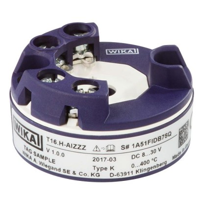
شكل يسارًا: النسخة المثبتة على الرأس، طراز T16.H شكل يمينًا: النسخة المثبتة على السكة، طراز T16.R
يتميز مرسل طراز T16 بوظائف مراقبة متنوعة، مثل مراقبة انقطاع الحساس ومراقبة نطاق القياس. علاوة على ذلك، تتمتع هذه المرسلات بوظيفة مراقبة ذاتية دورية شاملة.
المزايا
- لتوصيل جميع المزدوجات الحرارية القياسية
- دقة عالية
- الضبط باستخدام برنامج التكوين WIKAsoft-TT والتوصيل الكهربائي عبر الوصلة السريعة magWIK
- أطراف التوصيل متاحة أيضاً من الخارج
- استقرار التوافق الكهرومغناطيسي وفقًا لأحدث معيار (EN 61326-2-3:2013)
الأسئلة والأجوبة
ما هو نطاق القياس لدرجة الحرارة؟
يعتمد النطاق على نوع الثرموقبل المتصل؛ فالنطاقات المدعومة تشمل، من بين أمور أخرى، -270 … +400 °C و -50 … +1768 °C و 0 … 2315 °C، حسب نوع الحساس.
ما هي دقة المرسل؟
±0.045 % of ML عند الخرج، و ±0.6 K + 0.06 % MV عند الدخل لنوع Type K عند درجات حرارة ≥ 0 °C.
ما هو نوع الخرج وجهد التغذية؟
إشارة خرج تناظرية 4-20 mA، وتغذية DC 10 … 35 V.
هل يمكن استخدامه في المناطق الخطرة (Ex)؟
نعم؛ يدعم الطراز اعتمادات متعددة تشمل Ex ia IIC T6...T4 Ga للمنطقة 0، وEx ic IIC T6...T4 Gc X للمنطقة 2، وكذلك Class I, division 1 or 2, groups A/B/C/D, T6...T4.
ما هي الشهادات والوثائق المتوفرة؟
CE، RoHS، وتقرير اختبار 2.2 وشهادة فحص 3.1 وفق EN 10204.
كيف تتم تهيئة المرسل؟
عبر برنامج التهيئة WIKAsoft-TT مع وحدة البرمجة طراز PU-548، حيث يمكن اختيار نوع الحساس ونطاق القياس وتخميد الإشارة وتخزين سلوك الإشارة إلى الأخطاء.
ما الذي يميز نسخة T16.H عن T16.R؟
T16.H هي النسخة المركّبة على رأس الحساس، بينما T16.R هي النسخة المركّبة على السكة (rail-mounted).
ما وظائف المراقبة المتوفرة؟
يراقب المرسل انقطاع الحساس ونطاق القياس، ويؤدي وظيفة مراقبة ذاتية دورية شاملة.
اجمع T16 لمهمتك
يُبنى رقم المادة تلقائيًا. عند الشك — تواصل مع مهندس؛ سنساعدك حسب معطيات الخط.
- تصميمHead
- حماية من الانفجارWithout
- نوع الحماية من الاشتعالWithout
- حماية من الانفجار 1.اعتمادات إضافيةWithout
- حماية من الانفجار 2.اعتمادات إضافيةWithout
- مرسل درجة حرارة محيط مسموح بهStandard -40...85°C
- التكوين—
- مستشعر التهيئةThermocouple Type K
- تكوين الإدخالThermocouple (CJC internal)
- وحدة°C
- قيمة بداية نطاق القياس - الإشارةPlus (incl. 0)
- قيمة بداية مجال القياس0
- قيمة نهاية مجال القياس - الإشارةPlus (incl. 0)
- قيمة نهاية مجال القياس—
- إشارة المرسل لوجود خطأ—
- بروتوكول التهيئةWithout
- المثبتاتWithout
- الشهاداتWithout
أكمل التهيئة
اختر جميع الخيارات لإرسال الطلب.
| الطراز | T16.H |
| السلسلة | T16 |
| النوع الفرعي | Head-mounted transmitter |
| نطاق درجة الحرارة | −270…+1300 °C · −50…+1768 °C · −210…+1200 °C · +0…+1820 °C · −270…+400 °C · +0…+2315 °C · +0…+2500 °C · −200…+900 °C · −200…+800 °C · −270…+1000 °C |
| فئة الدقة | ±0.045 % of ML (output), ±0.6 K + 0.06 % MV (input for Type K ≥ 0 °C) |
| إشارة الخرج | 4-20mA |
| التغذية | DC 10 … 35 V |
| وصلة كهربائية | Cable |
| حرارة المحيط | −40…+85 °C |
| تصنيف IP | IP00 |
| الوزن | 0.05 kg |
| الشهادات | CERoHS2.2 test report per EN 102043.1 inspection certificate per EN 10204 |
| حماية الانفجار | Exi Zone 0 gas II 1G Ex ia IIC T6...T4 GaZone 20 dust II 1D Ex ia IIC T135 °C DaExi Zone 0 gas Ex ia IIC T6...T4 GaZone 2 gas Ex ic IIC T6...T4 Gc XExe Zone 2 gas Ex ec IIC T6...T4 Gc XII 1G Ex ia IIC T6...T4 GaII 3G Ex ic IIC T6...T4 Gc XII 1D Ex ia IIIC T135 °C DaEx ec IIC T6...T4 Gc XEx ia IIC/IIB/IIAEx ia IIICEx ic IIC/IIB/IIAEx ecEx ec IIC/IIB/IIAZone 1 gas II 3G Ex ic IIC T6...T4 Gc XExe Zone 2 gas II 3G Ex ec IIC T6...T4 Gc XClass I, division 1 or 2, groups A/B/C/D,T6...T4Class I, zone 0 or 1,AEx ia IIC T6...T4Class II, division 1 or 2, groups E/F/G,T6...T4/T135 °C,class IIIExi Zone 0 gas 0 Ex ia IIC T4/T5/T6Zone 1 gas 1 Ex ib IIC T4/T5/T6Zone 2 gas 2 Ex ic IIC T4/T5/T6Zone 20 dust DIP A20 Ta 135 °CZone 21 dust DIP A21 Ta 135 °CExe Zone 2 gas 2 Ex ec IIC T4/T5/T6 |
| نوع المستشعر | Type K |
| لغات ورقة البيانات | EN, DE |
| Case | T16.H head-mounted version | T16.R rail-mounted version |
|---|---|---|
| Material | PBT plastic, glass-fibre reinforced | Plastic |
| Weight | Approx. 50 g (approx. 1.76 oz) | Approx. 0.2 kg (approx. 7.1 oz) |
| Connection terminals, captive screws, wire cross-section | ||
| Solid wire | 0.14 ... 2.5 mm² (24 ... 14 AWG) | 0.14 ... 2.5 mm² (24 ... 14 AWG) |
| Stranded wire with end splice | 0.14 ... 1.5 mm² (24 ... 16 AWG) | 0.14 ... 2.5 mm² (24 ... 14 AWG) |
| Screwdriver | Cross head ('Pozidrive' tip), size 2 (ISO 8764) | Slotted, 3 x 0.5 mm(ISO 2380) |
| Tightening torque | 0.5Nm | 0.5Nm |
| Sensor type | Max. configurable measuring range | Standard | Min. measuring span (MS) |
|---|---|---|---|
| Thermocouple | |||
| J | -210 ... +1,200 °C [-346 ... +2,192 °F] | IEC 60584-1 | 50 K |
| K | -270 ... +1,300 °C [-454 ... +2,372 °F] | IEC 60584-1 | 50 K |
| B | 0 ... 1,820 °C [32 ... 3,308 °F] | IEC 60584-1 | 200 K |
| N | -270 ... +1,300 °C [-454 ... +2,372 °F] | IEC 60584-1 | 50 K |
| R | -50 ... +1,768 °C [-58 ... +3,214.4 °F] | IEC 60584-1 | 150 K |
| S | -50 ... +1,768 °C [-58 ... +3,214.4 °F] | IEC 60584-1 | 150 K |
| T | -270 ...+400 °C [-454 ...+752 °F] | IEC 60584-1 | 50 K |
| E | -270 ... +1,000 °C [-454 ... +1,832 °F] | IEC 60584-1 | 50 K |
| C | 0 ... 2,315 °C [32 ... 4,199 °F] | IEC 60584-1 | 150 K |
| A | 0 ... 2,500 °C [32 ... 4,532 °F] | IEC 60584-1 | 150 K |
| L (DIN 43710) | -200 ...+900 °C [-328 ... +1,652 °F] | DIN 43710 | 50 K |
| L (GOST R 8.585 - 2001) | -200 ...+800 °C -328 ... +1,472 °F] | - | 50 K |
| Input and output in accordance with IEC 62828 | ||||
|---|---|---|---|---|
| Input sensor type | Mean temperature coeffi - cient (TC) every 10 K ambi - ent temperature deviation from T ref | Measuring deviation at reference conditions 1) in accordance with DIN EN 60770, NE 145 2) | Influence of auxiliary power every 1 V voltage change from U i_ref | Long-term drift in line with IEC 61298-2 per year |
| Thermocouples | ||||
| Type J (Fe-CuNi) | ±1.7 K | ≤ 0 °C: 0.45 K + 0.3 %|MV| ≥ 0 °C: 0.45 K + 0.045%MV | ±0.005 %of ML | 40 µV / 0.1%MV (greater value applies) |
| Type K (NiCr-Ni) | ≤ 0 °C: 0.6 K + 0.3 %|MV| ≥ 0 °C: 0.6 K + 0.06%MV | |||
| Type L (DIN / Fe-CuNi) | ≤ 0 °C: 0.45 K + 0.15 %|MV| ≥ 0 °C: 0.45 K + 0.045%MV | |||
| Type L (GOST / Fe- CuNi) | ≤ 0 °C: 0.45 K + 0.15 %|MV| ≥ 0 °C: 0.45 K + 0.045%MV | |||
| Type E (NiCr-Cu) | ≤ 0 °C: 0.45 K + 0.3 %|MV| ≥ 0 °C: 0.45 K + 0.045%MV | |||
| Type N (NiCrSi-NiSi) | ≤ 0 °C: 0.75 K + 0.3 %|MV| ≥ 0 °C: 0.75 K + 0.045%MV | |||
| TypeT (Cu-CuNi) | ≤ 0 °C: 0.6 K + 0.3 %|MV| ≥ 0 °C: 0.6 K + 0.015%MV | |||
| Type R (PtRh-Pt) | ≤ 400 °C: 2.2 K + 0.18 %|MV| ≥ 400 °C: 2.2 K + 0.015%MV | |||
| Type S (PtRh-Pt) | ≤ 400 °C: 2.2 K + 0.18 %|MV| ≥ 400 °C: 2.2 K + 0.015%MV | |||
| Type B (PtRh-Pt) | ≤ 1,000 °C: 2.5 K + 0.3 %|MV - 1,000| ≥ 1,000 °C: 2.5 K | |||
| Type C (W5Re- W26Re) | ≤ 1,000 °C: 2.2 K + 0 %|MV| ≥ 1,000 °C: 2.2 K + 0.175%MV - 1,000 | |||
| Type A (W5Re- W20Re) | ≤ 1,000 °C: 2.4 K + 0 %|MV| ≥ 1,000 °C: 2.4 K + 0.175%MV - 1,000 | |||
| Cold junction (only with TC) | ±0.1 K (±1.8 °F) | ≤ ±1.5 K (≤ ±2.7 °F) | ≤ 0.4 K (≤ 0.72 °F) | |
| Output | 0.06 %of ML | 0.045 %of ML | 0.1 %of ML |
| Input 300 °C > 0 °C →0.6 K + 0.06 %xMV0.6 K + (0.06 %x300 °C) | ±0.78 K (±1.4 °F) |
|---|---|
| Output 0.045 %x300 K | ±0.135 K (±0.243 °F) |
| Cold junction 1.5 K | ±1.5 K (±2.7 °F) |
| Measuring deviation (typical) √input² + output² + cold junction² | ±1.7 K (±3.06 °F) |
| Measuring deviation (maximum) Input + TC input + output + cold junction | ±2.42 K (±4.36 °F) |
عرض الكل (17)
| Input 550 °C > 0 °C →0.6 K + 0.06%xMV 0.6 K + (0.06 %x550 °C) | ±0.93 K (±1.67 °F) |
|---|---|
| Temperature coefficient input 45 °C-26°C=9K→2x 10 K | ±0.4 K (±0.72 °F) |
| Output 0.045 %x600 K | ±0.27 K (±0.49 °F) |
| Temperature coefficient output 45 °C - 26°C=19K→2x 10 K 0.06 %x600 K x 2 | ±0.72 K (±1.3 °F) |
| Cold junction 1.5 K | ±1.5 K (±2.7 °F) |
| Cold junction temperature coefficient 45 °C - 26 °C = 19 K →2x10 K | ±4.0 K (±7.2 °F) |
| Measuring deviation (typical) √input² +TC input ² + output² +TC output ² + cold junction² + TC cold junction ² | ±4.5 K (±8.1 °F) |
| Measuring deviation (maximum) Input + TC input + output + cold junction | ±7.8 K (±14.04 °F) |
| Analogue output | Linear to temperature per IEC 60584 / DIN 43710 | |
|---|---|---|
| Output limits per NAMUR NE43 | Lower limit 3.8mA | Upper limit 20.5mA |
| Current value for signalling per NAMUR NE43 | Downscale < 3.6 mA(3.5 mA) | Upscale > 20.5 mA(21.5 mA) |
| Voltage supply | ||
| Auxiliary power U B | DC10…35V | |
| Load R A | R A ≤ (U B - 10 V) / 0.0215 A with R A in Ωand U B inV | |
| Ex-relevant connection values | See 'Safety-relevant characteristics (explosion-protected version)' | |
| Factory configuration | ||
| Sensor | Type K | |
| Measuring range | 0 ... 600 °C [32 ... 1,112 °F] | |
| Error signalling | Downscale | |
| Damping | Off | |
| Monitoring functions | ||
| Sensor break monitoring | Configurable via software Default: downscale | |
| Measuring range monitoring | Monitoring of the set measuring range for upper/lower deviations configurable Standard: deactivated | |
| Drag pointer (internal temperature of the electronics) | Stores the maximum ambient temperature (no reset possible) | |
| Time response | ||
| Step response time | < 0.9 s (typical < 0.7 s) | |
| Switch-on time | Max. 4 s | |
| Damping | Configurable between 1 s and 60 s | |
| Warm-up time | After a max. 45 minutes the accuracy specifications are met (due to the internal cold junction) | |
| Measuring rate | Measured value update approx. 8/s |
| Connection type | Cable | |
|---|---|---|
| Wire cross-section | ||
| T16.H head-mounted version | Solid wire | 0.14 ... 2.5 mm² (24 ... 14 AWG) |
| Stranded wire with end splice | 0.14 ... 1.5 mm² (24 ... 16 AWG) | |
| T16.R rail-mounted version | Solid wire | 0.14 ... 2.5 mm² (24 ... 14 AWG) |
| Stranded wire with end splice | 0.14 ... 2.5 mm² (24 ... 14 AWG) | |
| Insulation resistance R is | AC 1,500V |
| Ambient temperature range | {-50} -40 ...+85 {+105} °C [{-58} -40 ...+185 {+221} °F] |
|---|---|
| Storage temperature range | -40 ...+85 °C [-40 ...+185 °F] |
| Humidity | |
| Model T16.H per IEC 60068-2-38:2009 | Test max. temperature variation 65 °C (149 °F) / -10 °C (14 °F),93%±3% relative humidity (non-condensing) |
| Model T16.R per IEC 60068-2-30:2005 | Test max. temperature 55 °C (131 °F), 95 %relative humidity (condensation permissible in vertical mounting position) |
| Climate class per IEC 654-1:1993 | Cx (-40 ...+85 °C / -40 ...+185 °F, 5 ... 95 %r.h.) |
| Salz mist per IEC 68-2-52:1996, IEC 60068-2-52:1996 | Severity grade 1 |
| Vibration resistance per IEC 60068-2-6:2008 | Test Fc: 10 ... 2,000 Hz; 10 g, amplitude 0.75 mm(0.03 in) |
| Shock resistance per IEC 68-2-27:2009 | |
| Model T16.H | 100 g / 6 ms |
| Model T16.R | 30 g / 11 ms |
| Free fall per IEC 60721-3-2:1997, DIN EN 60721-3-2:1998 | Height of fall 1.5 m[4.9 ft] |
| Ingress protection of the complete instrument | |
| Head-mounted version | IP00 (electronics completely potted) |
| Rail-mounted version | IP20 |
| Electromagnetic compatibility (EMC) 1) per DIN EN 55011:2010, DIN EN 61326, NAMUR NE21:2012, GL 2012 VI Part 7 | Emission (group 1, class B) and immunity (industrial environment) [HF field, HF cable, ESD, Burst, Surge] |
| Logo | Description | Region |
|---|---|---|
| EU declaration of conformity | European Union |
| Logo | Description | Region | ||
|---|---|---|---|---|
| EU declaration of conformity | European Union | |||
| ATEX directive | ||||
| Hazardous areas | ||||
| - Ex i | Zone 0 gas | II 1G Ex ia IIC T6...T4 Ga | ||
| Zone 2 gas | II 3G Ex ic IIC T6...T4 Gc X | |||
| Zone 20 dust | II 1D Ex ia IIIC T135 °C Da | |||
| - Ex e | Zone 2 gas | II 3G Ex ec IIC T6...T4 Gc X | ||
| IECEx | International | |||
| Hazardous - Ex i | areas Zone 0 gas | Ex ia IIC T6...T4 Ga | ||
| Zone 2 gas | Ex ic IIC T6...T4 Gc X | |||
| Zone 20 dust | Ex ia IIIC T135 °C Da | |||
| - Ex e | Zone 2 gas | Ex ec IIC T6...T4 Gc X | ||
| FM | USA | |||
| Hazardous areas Class I, division 1 or 2, groups A/B/C/D, T6...T4 | ||||
| Class I, zone 0 or 1, AEx ia IIC T6...T4 | ||||
| CSA | Canada | |||
| Safety (e.g. electr. safety, overpressure, ...) | ||||
| Hazardous areas Class I, division 1 or 2, groups A/B/C/D, T6...T4 Class II, division 1 or 2, groups E/F/G, T6...T4 / T135 °C, class III Class I, zone 0 or 1, Ex ia [ia Ga] IIC T6...T4 Ga Class I, zone 20 or 21, Ex ia [ia Da] IIIC T135 °C Da | ||||
| EAC | Eurasian Economic Community | |||
| EMCDirective | ||||
| Hazardous areas | ||||
| Ex | ||||
| i Zone | 0 gas | 0 Ex ia IIC T4/T5/T6 | ||
| - | Zone 1 gas | 1 Ex ib IIC T4/T5/T6 | ||
| Zone 2 gas | 2 Ex ic IIC T4/T5/T6 | |||
| Zone | 20 dust | DIP A20Ta 135 °C | ||
| Zone 21 dust | DIP A21Ta 135 °C | |||
| - Ex e Zone 2 | gas | 2 Ex ec IIC T4/T5/T6 | ||
| Ex Ukraine | Ukraine | |||
| Mining | ||||
| Hazardous areas | ||||
| - Ex i | Zone 0 gas | II 1G Ex ia IIC T6...T4 Ga | ||
| Zone 20 dust | II 1D Ex ia IIIC T135 °C Da | |||
| - | PESO | India | ||
| Hazardous areas | ||||
| - Ex i | Zone 0 gas | Ex ia IIC T6...T4 Ga | ||
| Zone 2 gas | Ex ic IIC T6...T4 Gc X | |||
| Zone 20 dust | Ex ia IIIC T135 °C Da | |||
| - Ex e | Zone 2 gas | Ex ec IIC T6...T4 Gc X |
| Logo | Description | Region |
|---|---|---|
| PAC Kazakhstan Metrology, measurement technology | Kazakhstan | |
| PAC Uzbekistan Metrology, measurement technology | Uzbekistan |
| Certificates | ■ 2.2 test report per EN 10204 (e.g. state-of-the-art manufacturing, material proof, indication accuracy) ■ 3.1 inspection certificate per EN 10204 (e.g. material proof for wetted metal parts, indication accuracy, calibration certificate) |
|---|
| Safety-related characteristic values (Ex) | Models T16.x-AI, T16.x-AC Gas hazardous application | Model T16.x-AI Dust hazardous application |
|---|---|---|
| Connection values | ||
| Terminals | + / - | + / - |
| Max. voltage U i | DC 30V | DC 30V |
| Max. current I i | 130mA | 130mA |
| Max. power P i | 800mW | 750/650/550mW |
| Effective internal capacitance C i | 7.8 nF | 7.8 nF |
| Effective internal inductance L i | 20 µH | 20 µH |
| Connection values of sensor circuit | ||
| Terminals | 1 - 2 | 1 - 4 |
| Max. voltage U 0 | DC 6.6V | DC 6.6V |
| Max. current I 0 | 4mA | 4mA |
| Max. power P 0 | 10mW | 10mW |
| Characteristic curve | Linear |
| Application | Ambient temperature range | Temperature class | Power Pi |
|---|---|---|---|
| Group II | -40 °C [-40 °F] ≤T a ≤ +85 °C [+185 °F] | T4 | 800mW |
| -40 °C [-40 °F] ≤T a ≤ +70 °C [+158 °F] | T5 | 800mW | |
| -40 °C [-40 °F] ≤T a ≤ +55 °C [+131 °F] | T6 | 800mW | |
| Group IIIC | -40 °C [-40 °F] ≤T a ≤ +40 °C [+104 °F] | N/A | 750mW |
| -40 °C [-40 °F] ≤T a ≤ +75 °C [+167 °F] | N/A | 650mW | |
| -40 °C [-40 °F] ≤T a ≤ +85 °C [+185 °F] | N/A | 550mW |
| Safety-related characteristic values (Ex) | Model T16.x-AE |
|---|---|
| Gas hazardous application | |
| Connection values | |
| Protection level | Ex ec |
| Terminals | + / - |
| Max. voltage U i | DC 35V |
| Max. current I i | 21.5mA |
| Connection values of sensor circuit | |
| Protection level | Ex ec IIC/IIB/IIA |
| Terminals | 1 - 2 |
| Max. power P 0 | ■ 2.575V x 0.1 mA→0.256mW ■ DC 2.575V ■ 0.1mA |
| Application | Ambient temperature range | Temperature class |
|---|---|---|
| Group II | -40 °C [-40 °F] ≤T a ≤ +85 °C [+185 °F] | T4 |
| -40 °C [-40 °F] ≤T a ≤ +70 °C [+158 °F] | T5 | |
| -40 °C [-40 °F] ≤T a ≤ +55 °C [+131 °F] | T6 |
| Model | Description | Order number | |
|---|---|---|---|
| Programming unit model PU- 548 | Programming unit for USB interface for use with the WIKAsoft-TT configuration software Easy to use LED status display Compact design No further voltage supply needed, neither for the programming unit nor for the transmitter Incl.1 model magWIK magnetic quick connector | 14231581 | |
| Adapter | Suitable forTS 35 per DIN EN 60715 (DIN EN 50022) orTS 32 per DIN EN 50035 Material: plastic / stainless steel Dimensions: 60 x 20 x 41.6mm | 3593789 | |
| Adapter | Suitable forTS 35 per DIN EN 60715 (DIN EN 50022) Material: steel, tin-plated Dimensions:49x8x14mm | 3619851 | |
| Magnetic quick connector, model magWIK | Replacement for crocodile clips and HART ® terminals Fast, safe and secure electrical connection For all configuration and calibration processes | 14026893 |
لم تجد الإجابة في الوثائق؟ سيرد المهندس خلال يوم عمل.
اسأل المهندس →15 مادة قياسية من عائلة T16
إذا كنت تعرف الرمز — اختر مباشرة. إذا لا — استخدم المُهيِّئ في الوضع «01».