
 .
.
Для просмотра информации в формате PDF необходимо установить Adobe Acrobat Reader.

The HS 724 heater control system was originally developed in 1995 for control of heat emitter arrays in thermoforming machines.
Nowadays, the HS 724i heater control can be used to control heat emitter arrays and other resistive loads in industrial applications. The connection is made using PROFIBUS DP, and provides - e.g. together with the SIMATIC S7 - a highly modern and powerful automation system. An NE 724 line voltage detector can be integrated as an option in order to internally compensate variations in the line voltage automatically.
Область применения
The HS 724i heater control is used e.g. to control heat emitter arrays in
- thermoforming machines,
- blow molding machines,
- plastics welding machines,
- drying ovens
and other applications.
Дизайн
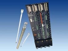
The main components of the HS 724i heater control are:
- ZA 724 central interface module
- NE 724 line voltage detector module (option)
- LA 724i /LA 724iHP/LA 724iSSR power outputs Up to 16 power outputs can be connected via the ZA 724 central interface module
- LM 724 fan module (option)
- SM 724i current measuring module (option)
- Communication via PROFIBUS DP e.g. with SIMOTION, SIMATIC S7, or industrial PC
The ZA 724 central interface module and the LA 724i/LA 724iHP/LA 724iSSR power outputs are each fitted in a metal encapsulation and mounted on a plate in the control cabinet. Customized, distributed solutions are also possible.
Технические данные
| HS 724i heater control | |
|---|---|
| Climatic conditions | |
| Operating temperature | |
| - Permissible range | 0 °C ... 55 °C |
| - Relative humidity at 25 °C | 95 % |
| - Temperature gradient | 10 K/h |
| Storage temperature | |
| - Permissible range | -40 °C ... 70 °C |
| - Relative humidity at 25 °C | 95 % |
| - Temperature gradient | 20 K/h |
| Atmospheric pressure during operation | |
| - Minimum | 860 hPa (= 1500 m above msl) (limited cooling performance at lower atmospheric pressure) |
| - Maximum | 1080 hPa |
| Atmospheric pressure during storage | |
| - Minimum | 660 hPa (= 3500 m above msl) |
| - Maximum | 1080 hPa |
| Ventilation | Self-ventilation or forced ventilation |
| Mechanical conditions | |
| Vibrations during operation (stationary use) | IEC 60068‑2‑6 test FC (10 cycles per axis) |
| - 10 Hz ... 58 Hz | 0.075 m amplitude |
| - 58 Hz ... 150 Hz | 9.8 m/s2 (= 1 g constant acceleration) |
| Vibrations during transport/storage (in shipping packaging) | IEC 60068‑2‑6 test FC (10 cycles per axis) |
| - 5 Hz ... 9 Hz | 3.5 mm amplitude |
| - 9 Hz ... 500 Hz | 9.8 m/s2 (= 1 g constant acceleration) |
| Shock during operation (stationary use) | IEC 60068‑2‑27 test EA 150 m/s2 [15 g, half-sine] duration 11 ms 3 shocks per axis and direction |
| Shock during transport/storage (in shipping packaging) | IEC 60068‑2‑29 test EB 250 m/s2 [25 g, half-sine] duration 6 ms 1000 shocks per axis and direction |
| Electromagnetic compatibility | |
| RI suppression (emitted interference) | Limit class A to EN 55011 group 1 |
| Noise immunity to conductive interferences (burst) | To EN 61000‑4‑4 |
| - AC power supply lines | 2 kV with switching network |
| - Signal lines which leave the unit | 2 kV with clip-on coupling device |
| Noise immunity to conductive interferences(RF injection) | To EN 61000‑4‑6 10 V (0.15 MHz ... 80 MHz) |
| Noise immunity to discharging of static electricity (ESD) | To EN 61000‑4‑2 |
| - Contact discharge | 4 kV |
| - Air discharge | 8 kV |
| Noise immunity to RF irradiation | EN 61000‑4‑3 or ENV 50204 10 V/m (80 MHz to 1000 MHz) 10 V/m pulse-modulated (900 ”5 MHz) |
| Noise immunity to high-energy pulses (surge) | To EN 61000‑4‑5 |
| Power supply lines | |
| - Symmetrical | 1 kV |
| - Unsymmetrical | 2 kV |
| PROFIBUS line | |
| - Unsymmetrical | 1 kV |