
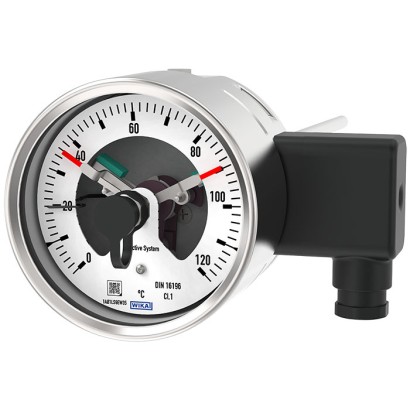
Биметаллический термометр с контактами переключателя
Описание
Там, где температура технологического процесса должна индицироваться на месте и при этом требуется выполнять переключение цепей, биметаллический термометр с контактами переключателя находит своё применение.
Контакты переключателя (электрические контакты сигнализации) замыкают или размыкают цепи в зависимости от положения стрелки измерительного прибора, осуществляющего индикацию. Контакты переключателя регулируются по всей измерительной шкале. Стрелка прибора (стрелка фактического значения) перемещается свободно по всему диапазону шкалы независимо от заданной установки.
Заданная стрелка может быть отрегулирована через окно с помощью съёмного регулировочного ключа (установленного на кабельном разъёме).
для дальнейших допусков см. стр. 8
Биметаллический термометр с контактами переключателя, модель TGS55
Контакты переключателя, состоящие из нескольких контактов, также могут быть установлены на один заданный уставочный пункт. Срабатывание контактов происходит, когда стрелка фактического значения проходит заданный уставочный пункт и опускается ниже него.
В качестве контактов переключателя доступны индуктивные контакты и электронные контакты. Индуктивные контакты могут применяться во взрывоопасных зонах. Для срабатывания программируемых логических контроллеров (PLC) могут использоваться электронные контакты.
Особенности
- Высокая надёжность и длительный срок службы
- Универсальное применение
- Корпус и штуцер из нержавеющей стали
- Приборы с индуктивными контактами для применения во взрывоопасных зонах
- Приборы с контактами для применений в ПЛК
Вопросы и ответы
Какие диапазоны измерения доступны у TGS55?
Доступны несколько диапазонов от -70 … +30 °C до 0 … +600 °C, например -50 … +50 °C, -20 … +140 °C, 0 … +200 °C, 0 … +300 °C, 0 … +500 °C.
Какая точность у прибора?
Точность соответствует Классу 1 или Классу 2 по DIN 16196 в зависимости от исполнения.
Какое присоединение к процессу предусмотрено?
Резьбовые присоединения M20 x 1.5, M24 x 1.5 (внутренняя резьба), G ½ B, ½ NPT, G ½ (внутренняя резьба), ½ NPT (внутренняя резьба), а также исполнение без резьбы.
Можно ли применять TGS55 во взрывоопасных зонах?
Да. Исполнения с индуктивными контактами имеют взрывозащиту ATEX и IECEx: Ex ia IIC T6/T5/T4 Gb для зоны 1 (газ) и Ex ia IIIB T85 °C/T95 °C/T100 °C/T135 °C Db для зоны 21 (пыль); предусмотрено также подтверждение EAC.
Какие типы контактов переключателя доступны?
Индуктивные контакты (модель 831) для взрывоопасных зон и электронные контакты (модель 830 E) для срабатывания программируемых логических контроллеров (PLC).
Для каких сред подходит прибор?
TGS55 предназначен для промышленного контроля процессов в агрессивных средах; корпус и гильза выполнены из нержавеющей стали 316SS.
Каковы температурные пределы эксплуатации?
Температура окружающей среды: -50 … +70 °C; температура измеряемой среды: -60 … +500 °C.
Какова степень защиты корпуса?
Степень защиты IP65.
Соберите TGS55 под свою задачу
Артикул собирается автоматически. Если сомневаетесь — напишите инженеру; подскажем по параметрам линии.
- Номинальный размер100
- Расположение присоединенияОсевое
- Тип присоединенияСтандартный, внешняя резьба
- ПереключательИндуктивный контакт, тип 831-N
- Действие первого контактазамыкающий (1)
- Действие второго контактабез
- ВзрывозащитаИсполнение по ATEX, IECEx, категории устройств 2G и 2D
- Электрическое присоединениеразъём сбоку
- Единица°C
- Диапазон шкалы-70 °C ... +30 °C
- Вторая шкалаБез
- Присоединение к процессуG 1/2 B
- Диаметр штока6 мм
- Погружная длина L1—
- ДемпфированиеБез
- Специальные конструктивные особенностиБез
- Сертификатыбез
- Разрешительные документыбез
- Дополнительная информация для заказабез
Завершите конфигурацию
Выберите все параметры, чтобы отправить запрос.
| Модель | TGS55 |
| Серия | TGS |
| Подтип | With switch contacts |
| Диапазон температуры | −70…+30 °C · −50…+50 °C · −30…+50 °C · −20…+140 °C · +0…+600 °C · −20…+60 °C · −20…+120 °C · +0…+60 °C · +0…+80 °C · +0…+100 °C · +0…+120 °C · +0…+160 °C · +0…+200 °C · +0…+250 °C · +0…+300 °C · +0…+400 °C · +0…+500 °C |
| Класс точности | Class 1, Class 2 per DIN 16196 |
| Технологическое присоединение | M20 x 1.5M24 x 1.5 femaleG ½ B½ NPTG ½ female½ NPT femalePlain, without thread |
| Темп. процесса | −60…+500 °C |
| Выходной сигнал | Inductive contact, model 831 · Electronic contact, model 830 E · Inductive contact · Electronic contact |
| Электр. соединение | Cable socket, black Per VDE 0110 insulation group C/250 V Cable gland M20 x 1.5 |
| Материал зонда | Stainless steel 316SS |
| Темп. окружающей среды | −50…+70 °C |
| Степень защиты IP | IP65 |
| Вес | 0.7 kg |
| Сертификаты | CERoHS |
| Взрывозащита | EACEx ia Zone 1 gas II 2G Ex ia IIC T6/T5/T4 GbZone 21 dust II 2D Ex ia IIIB T85°C/T95°C/T100°C/T135°C DbIECEx Ex ia Zone 1 gas Ex ia IIC T6/T5/T4 GbATEX: Ex ia Zone 1 gas II 2G Ex ia IIC T6/T5/T4 Gb, Zone 21 dust II 2D Ex ia IIIB T85°C/T95°C/T100°C/T135°C DbIECEx: Ex ia IIC T6/T5/T4 Gb, Zone 21 dust Ex ia IIIB T85°C/T95°C/T100°C/T135°C Db |
| Тип сенсора | bimetal |
| Длина зонда | 63 mm |
| Диаметр зонда | 8 mm |
| Защитная гильза | Нет |
| Языки datasheet | EN |
| Basic information | |
|---|---|
| Standard | DIN 16196 |
| Nominal size in mm[in] | 100 [4"] |
| Window | ■ Instrument glass ■ Laminated safety glass ■ Clear non-splintering plastic |
| Connection location | ■ Back mount (axial) ■ Lower mount (radial) ■ Back mount, adjustable stem and dial |
| Connection design | → For drawings, see page 9 |
| S | Standard (threaded connection) 1) |
| 1 | Plain stem (without thread) |
| 2 | Male nut |
| 3 | Union nut |
| 4 | Compression fitting (sliding on stem) |
| 5 | Union nut and loose threaded connection |
| 'Adjustable stem and dial' case version | 90° swivelling and 360° rotatable |
| Dampening, case filling | ■ Without ■ With liquid dampening |
| Material (in contact with the environment) | |
| Case, bayonet ring | ■ Stainless steel 304SS ■ Stainless steel 316SS |
| Type of measuring element | Bimetal coil |
|---|---|
| Nominal effective range | |
| Continuous load (1 year) | Measuring range (DIN 16196) |
| Short time (max. 24 h) | Scale range (DIN 16196) |
| Accuracy per DIN 16196 1) | With single contact | With double contact |
|---|---|---|
| Stem diameter 6 mm[0.24 in] | Class 2 | Class 2 |
| Stem diameter 8 mm[0.31 in] | Class 1 | Class 2 |
| Stem diameter ≥ 10 mm[0.39 in] | Class 1 | Class 1 |
| Scale range in °C | Measuring range 1) in °C | Scale interval in °C | Error limit in °C | |
|---|---|---|---|---|
| Class 1 | Class 2 | |||
| -70 ... +30 | -60 ...+20 | 1 | 1.5 | 3.0 |
| -50 ... +50 | -40 ...+40 | 1 | 1.5 | 3.0 |
| -30 ... +50 | -20 ...+40 | 1 | 1.5 | 3.0 |
| -20 ... +60 | -10 ...+50 | 1 | 1.5 | 3.0 |
| -20 ... +120 | 0 ... 100 | 2 | 3.0 | 6.0 |
| -20 ... +140 | 0 ... 120 | 2 | 3.0 | 6.0 |
| 0 ... 60 | 10 ... 50 | 1 | 1.5 | 3.0 |
| 0 ... 80 | 10 ... 70 | 1 | 1.5 | 3.0 |
| 0 ... 100 | 10 ... 90 | 1 | 1.5 | 3.0 |
| 0 ... 120 | 10 ... 110 | 2 | 3.0 | 6.0 |
| 0 ... 160 | 20 ... 140 | 2 | 3.0 | 6.0 |
| 0 ... 200 | 20 ... 180 | 2 | 3.0 | 6.0 |
| 0 ... 250 | 30 ... 220 | 5 | 3.75 | 7.0 |
| 0 ... 300 | 30 ... 270 | 5 | 7.5 | 15.0 |
| 0 ... 400 | 50 ... 350 | 5 | 7.5 | 15.0 |
| 0 ... 500 | 50 ... 450 | 5 | 7.5 | 15.0 |
| 0 ... 600 | 100 ... 500 | 10 | 15.0 | 30.0 |
Смотреть все (20)
| Unit | ■ °C ■ °F ■ °C/°F (dual scale) | |
|---|---|---|
| Dial | ||
| Scale graduation | ■ Single scale ■ Dual scale | |
| Scale colour | Single scale | Black |
| Dual scale | Red | |
| Other colours on request | ||
| Material | Aluminium | |
| Pointer | ||
| Version | Adjustable pointer | |
| Pointer colour | Black | |
| Material | Aluminium |
| Thread size | ■ Plain, without thread ■ G½B ■ ½NPT ■ G½female ■ ½NPTfemale ■ M20 x 1.5 ■ M24 x 1.5 female |
|---|---|
| Material (in contact with the environment) | Stainless steel 316SS |
| Stem | |
| Diameter | ■ 6 mm[0.24 in] ■ 8 mm[0.31 in] ■ 10 mm[0.39 in] ■ 12 mm[0.47 in] |
| Material (wetted) | Stainless steel 316SS |
| Thermowell/protection tube | In principle, the operation of a mechanical thermometer is possible without a thermowell/protection tube with low process-side loading (low pressure, low viscosity and low flow velocities). However, in order to enable exchanging the thermometer during operation (e.g. instrument replacement or calibration) and to ensure a better protection of the measuring instrument and also the plant and the environment, it is advisable to use a thermowell/protection tube from the extensiveWIKA portfolio. →For further information on the wake frequency calculation, see Technical information |
| Output signal | |
|---|---|
| Type of contact | ■ Inductive contact, model 831 (→ see page 5) ■ Electronic contact, model 830 E (→ see page 6) |
| Switching technology | |
| Inductive contact, model 831 | ■ Suitable for use in hazardous areas with corresponding control unit (model 904.xx) ■ Long service life due to non-contact sensor ■ Low influence on the indication accuracy ■ Fail-safe switching at high switching frequency ■ Insensitive to corrosion ■ Also available in safety version |
| Electronic contact, model 830 E | ■ For direct triggering of a programmable logic controller (PLC) ■ Long service life due to non-contact sensor ■ Low influence on the indication accuracy ■ Fail-safe switching at high switching frequency ■ Insensitive to corrosion |
| Contact setting | ■ Contact adjustable, adjustment key mounted on the cable socket ■ Contacts fixed, without adjustment lock ■ Contact adjustment lock leaded (tamper-proof) ■ Contact adjustment key fixed |
| Connection method | Inductive contact |
|---|---|
| Number of switch contacts | Max. 2 switch contacts |
| Switching function | Contact versions: ■ 831-N ■ 831-SN, safety version 1) ■ 831-S1N, safety version 1) , inverted signal The switching function of each switch is indicated by index 1 or 2 |
| Model 831.1 | Normally open (clockwise pointer motion) |
| Model 831.2 | Normally closed (clockwise pointer motion) |
| Switch point setting | Set pointers of the contact pressure gauges are freely adjustable over the full scale range |
| Setting range (recommended) | 10 ... 90 %of the scale range (0 ... 100 %onrequest) |
| Distance between switch points | Up to 2 contacts can be set to an identical set point. For a version with 3 contacts this is not possible.The left (no. 1) or right (no. 3) contact may not be set to the same set point as the other 2 contacts.The required displacement is approx. 30°, optionally to the right or to the left. |
| Switching current | Depending on the isolating amplifier/control unit used (→ see data sheet AC 08.01) |
| Switching voltage | Depending on the isolating amplifier/control unit used (→ see data sheet AC 08.01) |
| Switching power | Depending on the isolating amplifier/control unit used (→ see data sheet AC 08.01) |
| Permissible temperature ranges in hazardous areas | |
| T6 | -20 ...+60 °C [-4 ...+140 °F] |
| T5 ...T1 | -20 ...+70 °C [-4 ...+158 °F] |
| T135°C | -20 ...+70 °C [-4 ...+158 °F] |
| Model | Version | Ex version |
|---|---|---|
| 904.28 KFU8 - SR2 - Ex1.W | 1 contact | Yes |
| 904.29 KFU8 - SR2 - Ex2.W | 2 contacts | Yes |
| 904.30 KHA6 - SH - Ex1 | 1 contact | Yes - Safety version |
| 904.33 KFD2 - SH - Ex1 | 1 contact | Yes - Safety version |
| 904.25 MSR 010-I | 1 contact | No |
| 904.26 MSR 020-I | 2 contacts | No |
| 904.27 MSR 011-I | Two-point control | No |
| Connection method | Electronic contact (PNP transistor) |
|---|---|
| Number of switch contacts | Max. 2 switch contacts |
| Switching function | Contact versions: ■ 2-wire system ■ 3-wire system The switching function of each switch is indicated by index 1 or 2 |
| Model 830 E.1 | Normally open (clockwise pointer motion) |
| Model 830 E.2 | Normally closed (clockwise pointer motion) |
| Setting range (recommended) | 10 ... 90 %of the scale range (0 ... 100 %onrequest) |
| Distance between switch points | Up to 2 contacts can be set to an identical set point. For a version with 3 contacts this is not possible.The left (no. 1) or right (no. 3) contact may not be set to the same set point as the other 2 contacts.The required displacement is approx. 30°, optionally to the right or to the left. |
| Switching current | ≤ 100mA |
| Switching voltage | DC 10 ...30V |
| Type of output | PNP transistor |
| Residual ripple | Max.10% |
| No-load current | ≤ 10mA |
| Residual current | ≤ 100 µA |
| Voltage drop (with I max. ) | ≤ 0.7V |
| Reverse polarity protection | Conditional U B (the switched output 3 or 4 must never be set directly to minus) |
| Anti-inductive protection | 1 kV, 0.1 ms, 1 kΩ |
| Oscillator frequency | Approx. 1,000 kHz |
| EMC | Per EN 60947-5-2 |
| Connection type | ■ Cable socket, black PerVDE 0110 insulation group C/250V Cable gland M20 x 1.5 ■ Connector ■ Rear cable outlet |
|---|---|
| Wire cross-section | 6 screw terminals + PE for conductor cross-section 2.5 mm² |
| Cable diameter | → See dimensions from page 10 |
| Pin assignment | Connection details are given on the product label of the instrument. Connection terminals and ground terminals are appropriately marked. |
| Material | PA 6 (polyamide) |
| Ambient temperature range (at the case) 1) | -20 ...+60 °C [-4 ...+140 °F] |
|---|---|
| Storage temperature range 1) | |
| Without liquid dampening | -50 ...+70 °C [-58 ...+158 °F] |
| With liquid dampening | -40 ...+70 °C [-40 ...+158 °F] |
| Max. operating pressure at stem | Max. 25 bar [362.59 psi], static |
| Ingress protection (IP code) per IEC/EN 60529 | ■ IP65 ■ IP66 |
| Logo | Description | Country |
|---|---|---|
| EU declaration of conformity | European Union | |
| EMCdirective | ||
| Low voltage directive | ||
| RoHS directive |
| Logo | Description | Country |
|---|---|---|
| EU declaration of conformity | European Union | |
| IECEx 1) Hazardous areas - Ex ia Zone 1 gas Ex ia IIC T6/T5/T4 Gb Zone 21 dust Ex ia IIIB T85°C/T95°C/T100°C/T135°C Db | International | |
| EAC EMCdirective Hazardous areas 1) | Eurasian Economic Community | |
| KazInMetr Metrology, measurement technology | Kazakhstan | |
| - | MTSCHS Permission for commissioning | Kazakhstan |
| UkrSEPRO Metrology, measurement technology | Ukraine | |
| Ex Ukraine Hazardous areas | Ukraine | |
| Uzstandard Metrology, measurement technology | Uzbekistan | |
| - | CRN Safety (e.g. electr. safety, overpressure, ...) | Canada |
| Certificates | ■ 2.2 test report ■ 3.1 inspection certificate with 3 test points (optionally with 5 test points) |
|---|---|
| Calibration | DAkkS calibration certificate |
| Nominal size | i i l 2 l SW 1 Dimensions inmm l 1 | |||
|---|---|---|---|---|
| NS | d 1 | Ød d 1 | 1 a for axial | i 2 l a for adjustable stem and dial Ø d |
| Bauform 100 | SW 5 18 | 8 | l 2 15 | 25 |
| Nominal size | ca.40 l l 2 1 Process connection | Dimensions inmm 3073050.06 | ||
|---|---|---|---|---|
| NS | G | i | SW | Ø d |
| 100 | G½B | 8.5 L | 27 | 8 |
| G¾B | 10.5 | 32 | 8 | |
| M24 x 1.5 | 13.5 | 32 | 8 |
| Nominal size | l a l 2 G SW Process connection | Dimensions inmm | |||
|---|---|---|---|---|---|
| SW NS | G | 1 i | SW | d 4 | 3073050.06 Ø d Bauform |
| 100 | G½B | 14 | d d 27 | 26 | 8 Design 1 |
| G¾B | 16 | Ø 32 | 32 | Bauform 3 8 | |
| ½NPT | 19 | 22 | - | 3073050.06 Design 3 8 | |
| ¾NPT | 20 | 30 | - | 8 |
| Nominal size | i i Process connection | Dimensions inmm Bauform Design | ||
|---|---|---|---|---|
| 25 NS | SW G | i | SW | Ø d |
| Ø22 100 | G½B | 20 | G 27 | 8 |
| l Nominal size | Process connection | Dimensions inmm | |||
|---|---|---|---|---|---|
| l 1 NS | G | i | SW | d 4 | Ø d |
| 100 | G½B | 14 | 27 | 26 | 8 |
| G | ca.40 Ø d d G¾B | 16 | 32 | 32 | 8 |
| M18 x 1.5 | L 12 | 24 | 23 | 8 | |
| ½NPT | 19 | 22 | - | 8 | |
| l 2 | ¾NPT | 20 | 30 | - | 8 |
Не нашли ответа в документации? Инженер ответит в течение рабочего дня.
Спросить инженера →17 стандартных артикулов семейства TGS
Если знаете код — выберите напрямую. Если нет — пользуйтесь конфигуратором в режиме «01».