
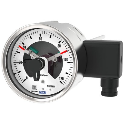
Біметалевий термометр із контактами перемикача
Опис
У тих випадках, коли температуру технологічного процесу потрібно вказувати на місці, а водночас необхідно здійснювати перемикання кіл, біметалевий термометр із контактами перемикача знаходить своє застосування.
Контакти перемикача (електричні контакти сигналізації) замикають або розмикають кола залежно від положення стрілки вимірювальних приладів, що виконують індикацію. Контакти перемикача регулюються в межах усього діапазону вимірювання. Стрілка приладу (стрілка фактичного значення) вільно переміщується по всьому діапазону шкали незалежно від налаштування.
Налаштовану стрілку можна відрегулювати через вікно за допомогою знімного ключа для регулювання (встановленого на роз’ємі кабелю).
для подальших погоджень див. стор. 8
Біметалевий термометр із контактами перемикача, модель TGS55
Контакти перемикача, що складаються з кількох контактів, також можна налаштувати на один заданий поріг. Спрацьовування контакту відбувається, коли стрілка фактичного значення проходить за межі та нижче бажаного заданого порогу.
Як контакти перемикача доступні індуктивні контакти та електронні контакти. Індуктивні контакти можна застосовувати у вибухонебезпечних зонах. Для спрацювання програмованих логічних контролерів (PLC) можна використовувати електронні контакти.
Особливості
- Висока надійність та тривалий термін служби
- Універсальне застосування
- Корпус і занурювальна частина з нержавіючої сталі
- Прилади з індуктивними контактами для використання у вибухонебезпечних зонах
- Прилади з контактами для застосувань у PLC
Питання та відповіді
Який діапазон вимірювання має цей термометр?
Залежно від виконання шкали доступні діапазони від -70 … +30 °C до 0 … +600 °C; температура середовища може становити від -60 до +500 °C.
Яка точність вимірювання?
Клас 1 або Клас 2 за DIN 16196, залежно від виконання.
Які варіанти приєднання до процесу доступні?
M20 x 1.5, M24 x 1.5 (внутрішнє), G ½ B, ½ NPT, внутрішні різьби G ½ та ½ NPT, а також виконання без різьби.
Чи можна використовувати прилад у вибухонебезпечних зонах?
Так, виконання з індуктивними контактами має сертифікацію ATEX та IECEx для зони 1 (газ, Ex ia IIC T6/T5/T4 Gb) і зони 21 (пил, Ex ia IIIB).
Які типи контактів перемикача пропонуються?
Індуктивний контакт моделі 831 (для вибухонебезпечних зон) та електронний контакт моделі 830 E (для спрацювання PLC).
Які матеріали використані для частин, що контактують із середовищем?
Гільза виготовлена з нержавіючої сталі 316SS, що робить прилад придатним для агресивних середовищ.
Який ступінь захисту корпусу?
Ступінь захисту IP65.
Чим TGS55 відрізняється від звичайного біметалевого термометра?
TGS55 поєднує локальну індикацію температури з контактами перемикача, які регулюються в межах усього діапазону вимірювання через вікно за допомогою знімного ключа, що дозволяє одночасно здійснювати сигналізацію та перемикання кіл.
Зберіть TGS55 під свою задачу
Артикул збирається автоматично. Якщо сумніваєтесь — напишіть інженеру; підкажемо за параметрами лінії.
- Номінальний розмір100
- Місце підключеннязаднє приєднання
- Конструкція приєднаннястандарт, зовнішня різьба
- вимикачіндуктивний кінцевий вимикач, версія 831-N
- перша операція перемикачаmakes (1)
- друга операція перемикачабез
- ВибухозахистIECEx, ATEX тип вибухозахисту ia з категорією обладнання 2G та 2D
- Електричне підключеннябокова частина штекера
- Одиниця°C
- Діапазон шкали-70 °C ... +30 °C
- 2-й масштаббез
- Приєднання до процесуG 1/2 B
- Діаметр штока6 мм
- Довжина занурення L1—
- Затуханнябез
- Спеціальні конструктивні особливостібез
- Сертифікатибез
- Схваленнябез
- Додаткова інформація для замовленняБез
Завершіть конфігурацію
Оберіть всі параметри, щоб надіслати запит.
| Модель | TGS55 |
| Сімейство | TGS |
| Підтип | With switch contacts |
| Діапазон температури | −70…+30 °C · −50…+50 °C · −30…+50 °C · −20…+140 °C · +0…+600 °C · −20…+60 °C · −20…+120 °C · +0…+60 °C · +0…+80 °C · +0…+100 °C · +0…+120 °C · +0…+160 °C · +0…+200 °C · +0…+250 °C · +0…+300 °C · +0…+400 °C · +0…+500 °C |
| Клас точності | Class 1, Class 2 per DIN 16196 |
| Технологічне приєднання | M20 x 1.5M24 x 1.5 femaleG ½ B½ NPTG ½ female½ NPT femalePlain, without thread |
| Темп. процесу | −60…+500 °C |
| Вихідний сигнал | Inductive contact, model 831 · Electronic contact, model 830 E · Inductive contact · Electronic contact |
| Електр. приєднання | Cable socket, black Per VDE 0110 insulation group C/250 V Cable gland M20 x 1.5 |
| Матеріал зонда | Stainless steel 316SS |
| Темп. навколишнього середовища | −50…+70 °C |
| Ступінь захисту IP | IP65 |
| Вага | 0.7 kg |
| Сертифікати | CERoHS |
| Вибухозахист | EACEx ia Zone 1 gas II 2G Ex ia IIC T6/T5/T4 GbZone 21 dust II 2D Ex ia IIIB T85°C/T95°C/T100°C/T135°C DbIECEx Ex ia Zone 1 gas Ex ia IIC T6/T5/T4 GbATEX: Ex ia Zone 1 gas II 2G Ex ia IIC T6/T5/T4 Gb, Zone 21 dust II 2D Ex ia IIIB T85°C/T95°C/T100°C/T135°C DbIECEx: Ex ia IIC T6/T5/T4 Gb, Zone 21 dust Ex ia IIIB T85°C/T95°C/T100°C/T135°C Db |
| Тип сенсора | bimetal |
| Довжина зонда | 63 mm |
| Діаметр зонда | 8 mm |
| Захисна гільза | Ні |
| Мови datasheet | EN |
| Basic information | |
|---|---|
| Standard | DIN 16196 |
| Nominal size in mm[in] | 100 [4"] |
| Window | ■ Instrument glass ■ Laminated safety glass ■ Clear non-splintering plastic |
| Connection location | ■ Back mount (axial) ■ Lower mount (radial) ■ Back mount, adjustable stem and dial |
| Connection design | → For drawings, see page 9 |
| S | Standard (threaded connection) 1) |
| 1 | Plain stem (without thread) |
| 2 | Male nut |
| 3 | Union nut |
| 4 | Compression fitting (sliding on stem) |
| 5 | Union nut and loose threaded connection |
| 'Adjustable stem and dial' case version | 90° swivelling and 360° rotatable |
| Dampening, case filling | ■ Without ■ With liquid dampening |
| Material (in contact with the environment) | |
| Case, bayonet ring | ■ Stainless steel 304SS ■ Stainless steel 316SS |
| Type of measuring element | Bimetal coil |
|---|---|
| Nominal effective range | |
| Continuous load (1 year) | Measuring range (DIN 16196) |
| Short time (max. 24 h) | Scale range (DIN 16196) |
| Accuracy per DIN 16196 1) | With single contact | With double contact |
|---|---|---|
| Stem diameter 6 mm[0.24 in] | Class 2 | Class 2 |
| Stem diameter 8 mm[0.31 in] | Class 1 | Class 2 |
| Stem diameter ≥ 10 mm[0.39 in] | Class 1 | Class 1 |
| Scale range in °C | Measuring range 1) in °C | Scale interval in °C | Error limit in °C | |
|---|---|---|---|---|
| Class 1 | Class 2 | |||
| -70 ... +30 | -60 ...+20 | 1 | 1.5 | 3.0 |
| -50 ... +50 | -40 ...+40 | 1 | 1.5 | 3.0 |
| -30 ... +50 | -20 ...+40 | 1 | 1.5 | 3.0 |
| -20 ... +60 | -10 ...+50 | 1 | 1.5 | 3.0 |
| -20 ... +120 | 0 ... 100 | 2 | 3.0 | 6.0 |
| -20 ... +140 | 0 ... 120 | 2 | 3.0 | 6.0 |
| 0 ... 60 | 10 ... 50 | 1 | 1.5 | 3.0 |
| 0 ... 80 | 10 ... 70 | 1 | 1.5 | 3.0 |
| 0 ... 100 | 10 ... 90 | 1 | 1.5 | 3.0 |
| 0 ... 120 | 10 ... 110 | 2 | 3.0 | 6.0 |
| 0 ... 160 | 20 ... 140 | 2 | 3.0 | 6.0 |
| 0 ... 200 | 20 ... 180 | 2 | 3.0 | 6.0 |
| 0 ... 250 | 30 ... 220 | 5 | 3.75 | 7.0 |
| 0 ... 300 | 30 ... 270 | 5 | 7.5 | 15.0 |
| 0 ... 400 | 50 ... 350 | 5 | 7.5 | 15.0 |
| 0 ... 500 | 50 ... 450 | 5 | 7.5 | 15.0 |
| 0 ... 600 | 100 ... 500 | 10 | 15.0 | 30.0 |
Переглянути всі (20)
| Unit | ■ °C ■ °F ■ °C/°F (dual scale) | |
|---|---|---|
| Dial | ||
| Scale graduation | ■ Single scale ■ Dual scale | |
| Scale colour | Single scale | Black |
| Dual scale | Red | |
| Other colours on request | ||
| Material | Aluminium | |
| Pointer | ||
| Version | Adjustable pointer | |
| Pointer colour | Black | |
| Material | Aluminium |
| Thread size | ■ Plain, without thread ■ G½B ■ ½NPT ■ G½female ■ ½NPTfemale ■ M20 x 1.5 ■ M24 x 1.5 female |
|---|---|
| Material (in contact with the environment) | Stainless steel 316SS |
| Stem | |
| Diameter | ■ 6 mm[0.24 in] ■ 8 mm[0.31 in] ■ 10 mm[0.39 in] ■ 12 mm[0.47 in] |
| Material (wetted) | Stainless steel 316SS |
| Thermowell/protection tube | In principle, the operation of a mechanical thermometer is possible without a thermowell/protection tube with low process-side loading (low pressure, low viscosity and low flow velocities). However, in order to enable exchanging the thermometer during operation (e.g. instrument replacement or calibration) and to ensure a better protection of the measuring instrument and also the plant and the environment, it is advisable to use a thermowell/protection tube from the extensiveWIKA portfolio. →For further information on the wake frequency calculation, see Technical information |
| Output signal | |
|---|---|
| Type of contact | ■ Inductive contact, model 831 (→ see page 5) ■ Electronic contact, model 830 E (→ see page 6) |
| Switching technology | |
| Inductive contact, model 831 | ■ Suitable for use in hazardous areas with corresponding control unit (model 904.xx) ■ Long service life due to non-contact sensor ■ Low influence on the indication accuracy ■ Fail-safe switching at high switching frequency ■ Insensitive to corrosion ■ Also available in safety version |
| Electronic contact, model 830 E | ■ For direct triggering of a programmable logic controller (PLC) ■ Long service life due to non-contact sensor ■ Low influence on the indication accuracy ■ Fail-safe switching at high switching frequency ■ Insensitive to corrosion |
| Contact setting | ■ Contact adjustable, adjustment key mounted on the cable socket ■ Contacts fixed, without adjustment lock ■ Contact adjustment lock leaded (tamper-proof) ■ Contact adjustment key fixed |
| Connection method | Inductive contact |
|---|---|
| Number of switch contacts | Max. 2 switch contacts |
| Switching function | Contact versions: ■ 831-N ■ 831-SN, safety version 1) ■ 831-S1N, safety version 1) , inverted signal The switching function of each switch is indicated by index 1 or 2 |
| Model 831.1 | Normally open (clockwise pointer motion) |
| Model 831.2 | Normally closed (clockwise pointer motion) |
| Switch point setting | Set pointers of the contact pressure gauges are freely adjustable over the full scale range |
| Setting range (recommended) | 10 ... 90 %of the scale range (0 ... 100 %onrequest) |
| Distance between switch points | Up to 2 contacts can be set to an identical set point. For a version with 3 contacts this is not possible.The left (no. 1) or right (no. 3) contact may not be set to the same set point as the other 2 contacts.The required displacement is approx. 30°, optionally to the right or to the left. |
| Switching current | Depending on the isolating amplifier/control unit used (→ see data sheet AC 08.01) |
| Switching voltage | Depending on the isolating amplifier/control unit used (→ see data sheet AC 08.01) |
| Switching power | Depending on the isolating amplifier/control unit used (→ see data sheet AC 08.01) |
| Permissible temperature ranges in hazardous areas | |
| T6 | -20 ...+60 °C [-4 ...+140 °F] |
| T5 ...T1 | -20 ...+70 °C [-4 ...+158 °F] |
| T135°C | -20 ...+70 °C [-4 ...+158 °F] |
| Model | Version | Ex version |
|---|---|---|
| 904.28 KFU8 - SR2 - Ex1.W | 1 contact | Yes |
| 904.29 KFU8 - SR2 - Ex2.W | 2 contacts | Yes |
| 904.30 KHA6 - SH - Ex1 | 1 contact | Yes - Safety version |
| 904.33 KFD2 - SH - Ex1 | 1 contact | Yes - Safety version |
| 904.25 MSR 010-I | 1 contact | No |
| 904.26 MSR 020-I | 2 contacts | No |
| 904.27 MSR 011-I | Two-point control | No |
| Connection method | Electronic contact (PNP transistor) |
|---|---|
| Number of switch contacts | Max. 2 switch contacts |
| Switching function | Contact versions: ■ 2-wire system ■ 3-wire system The switching function of each switch is indicated by index 1 or 2 |
| Model 830 E.1 | Normally open (clockwise pointer motion) |
| Model 830 E.2 | Normally closed (clockwise pointer motion) |
| Setting range (recommended) | 10 ... 90 %of the scale range (0 ... 100 %onrequest) |
| Distance between switch points | Up to 2 contacts can be set to an identical set point. For a version with 3 contacts this is not possible.The left (no. 1) or right (no. 3) contact may not be set to the same set point as the other 2 contacts.The required displacement is approx. 30°, optionally to the right or to the left. |
| Switching current | ≤ 100mA |
| Switching voltage | DC 10 ...30V |
| Type of output | PNP transistor |
| Residual ripple | Max.10% |
| No-load current | ≤ 10mA |
| Residual current | ≤ 100 µA |
| Voltage drop (with I max. ) | ≤ 0.7V |
| Reverse polarity protection | Conditional U B (the switched output 3 or 4 must never be set directly to minus) |
| Anti-inductive protection | 1 kV, 0.1 ms, 1 kΩ |
| Oscillator frequency | Approx. 1,000 kHz |
| EMC | Per EN 60947-5-2 |
| Connection type | ■ Cable socket, black PerVDE 0110 insulation group C/250V Cable gland M20 x 1.5 ■ Connector ■ Rear cable outlet |
|---|---|
| Wire cross-section | 6 screw terminals + PE for conductor cross-section 2.5 mm² |
| Cable diameter | → See dimensions from page 10 |
| Pin assignment | Connection details are given on the product label of the instrument. Connection terminals and ground terminals are appropriately marked. |
| Material | PA 6 (polyamide) |
| Ambient temperature range (at the case) 1) | -20 ...+60 °C [-4 ...+140 °F] |
|---|---|
| Storage temperature range 1) | |
| Without liquid dampening | -50 ...+70 °C [-58 ...+158 °F] |
| With liquid dampening | -40 ...+70 °C [-40 ...+158 °F] |
| Max. operating pressure at stem | Max. 25 bar [362.59 psi], static |
| Ingress protection (IP code) per IEC/EN 60529 | ■ IP65 ■ IP66 |
| Logo | Description | Country |
|---|---|---|
| EU declaration of conformity | European Union | |
| EMCdirective | ||
| Low voltage directive | ||
| RoHS directive |
| Logo | Description | Country |
|---|---|---|
| EU declaration of conformity | European Union | |
| IECEx 1) Hazardous areas - Ex ia Zone 1 gas Ex ia IIC T6/T5/T4 Gb Zone 21 dust Ex ia IIIB T85°C/T95°C/T100°C/T135°C Db | International | |
| EAC EMCdirective Hazardous areas 1) | Eurasian Economic Community | |
| KazInMetr Metrology, measurement technology | Kazakhstan | |
| - | MTSCHS Permission for commissioning | Kazakhstan |
| UkrSEPRO Metrology, measurement technology | Ukraine | |
| Ex Ukraine Hazardous areas | Ukraine | |
| Uzstandard Metrology, measurement technology | Uzbekistan | |
| - | CRN Safety (e.g. electr. safety, overpressure, ...) | Canada |
| Certificates | ■ 2.2 test report ■ 3.1 inspection certificate with 3 test points (optionally with 5 test points) |
|---|---|
| Calibration | DAkkS calibration certificate |
| Nominal size | i i l 2 l SW 1 Dimensions inmm l 1 | |||
|---|---|---|---|---|
| NS | d 1 | Ød d 1 | 1 a for axial | i 2 l a for adjustable stem and dial Ø d |
| Bauform 100 | SW 5 18 | 8 | l 2 15 | 25 |
| Nominal size | ca.40 l l 2 1 Process connection | Dimensions inmm 3073050.06 | ||
|---|---|---|---|---|
| NS | G | i | SW | Ø d |
| 100 | G½B | 8.5 L | 27 | 8 |
| G¾B | 10.5 | 32 | 8 | |
| M24 x 1.5 | 13.5 | 32 | 8 |
| Nominal size | l a l 2 G SW Process connection | Dimensions inmm | |||
|---|---|---|---|---|---|
| SW NS | G | 1 i | SW | d 4 | 3073050.06 Ø d Bauform |
| 100 | G½B | 14 | d d 27 | 26 | 8 Design 1 |
| G¾B | 16 | Ø 32 | 32 | Bauform 3 8 | |
| ½NPT | 19 | 22 | - | 3073050.06 Design 3 8 | |
| ¾NPT | 20 | 30 | - | 8 |
| Nominal size | i i Process connection | Dimensions inmm Bauform Design | ||
|---|---|---|---|---|
| 25 NS | SW G | i | SW | Ø d |
| Ø22 100 | G½B | 20 | G 27 | 8 |
| l Nominal size | Process connection | Dimensions inmm | |||
|---|---|---|---|---|---|
| l 1 NS | G | i | SW | d 4 | Ø d |
| 100 | G½B | 14 | 27 | 26 | 8 |
| G | ca.40 Ø d d G¾B | 16 | 32 | 32 | 8 |
| M18 x 1.5 | L 12 | 24 | 23 | 8 | |
| ½NPT | 19 | 22 | - | 8 | |
| l 2 | ¾NPT | 20 | 30 | - | 8 |
Не знайшли відповіді у документації? Інженер відповість впродовж робочого дня.
Запитати інженера →17 стандартних артикулів сімейства TGS
Якщо знаєте код — оберіть напряму. Якщо ні — користуйтесь конфігуратором у режимі «01».