
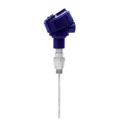
Термопара
Описание
Термопары этой серии можно комбинировать с большим количеством конструкций термокарманов. Эксплуатация без термокарманов допускается при использовании неподвижного (приварного) присоединительного штуцера.
Для термометров доступно большое разнообразие возможных комбинаций датчика, соединительной головки, длины погружения, длины шейки, присоединения к термокарману и т. д.; они подходят практически для любых размеров термокарманов.
для получения дополнительных одобрений см. стр. 2
Термопара, модель TC10-0, промышленная сборка
Особенности
- Диапазоны измерений чувствительного элемента от -40 ... +1,260 °C [-40 ... +2,300 °F]
- Для монтажа во все стандартные конструкции защитных гильз
- Пружинный измерительный вкладыш (сменный)
- Взрывозащищённые исполнения
- Стационарно закреплённый (сварной) измерительный вкладыш
Вопросы и ответы
Какой диапазон температур измеряет термопара TC10-0?
Диапазоны измерения — от -40 °C до +1 260 °C в зависимости от калибровки; доступны также варианты с верхними пределами +350 … +1 200 °C.
Какие типы термопар доступны?
Type K, J, E, N и T с классами допуска Class 1, Class 2, Standard или Special.
Как монтируется сборка?
В стандартные защитные гильзы (с подпружиненным вкладышем) либо с фиксированным приварным присоединением. Присоединительные резьбы: ½ NPT, ¾ NPT, G ½ B, G ¾ B, M14 x 1.5, M18 x 1.5, M20 x 1.5, M24 x 1.5, конические и параллельные резьбы, а также варианты шейки nipple-union-nipple, неразъёмной шейки и двойной шестигранной муфты.
Какое взрывозащищённое исполнение доступно?
Доступны Ex i (газ: зоны 0, 1, 2; пыль: зоны 20, 21, 22), Ex d (газ: зоны 1, 2), Ex e, Ex n/Ex nA (зона 2) и Ex t (пыль). Маркировки включают ATEX II 1G Ex ia IIC T1…T6 Ga, IECEx Ex ia IIC T1…T6 Ga, FM и CSA Class I, Div 1, Groups B, C, D, T6.
Какая степень защиты корпуса?
IP65.
Подходит ли модель для систем безопасности SIL?
Да, сборка соответствует уровню полноты безопасности SIL 2 по IEC 61508 / IEC 61511.
Чем TC10-0 отличается от соседних моделей серии?
TC10-0 — промышленная сборка с подпружиненным заменяемым измерительным вкладышем для стандартных гильз; также доступно исполнение с неподвижным (приварным) присоединением вкладыша без гильзы.
Какой выходной сигнал обеспечивает прибор?
HART и аналоговый сигнал 4 … 20 mA.
| Модель | TC10-0 |
| Серия | TC10 |
| Подтип | Thermocouple |
| Диапазон температуры | −40…+1260 °C · −40…+1200 °C · −40…+1000 °C · −40…+900 °C · −40…+800 °C · −40…+750 °C · −40…+350 °C · +0…+1260 °C · +0…+870 °C · +0…+760 °C · +0…+370 °C |
| Уровень функциональной безопасности (SIL) | SIL 2 (IEC 61508 / IEC 61511) |
| Технологическое присоединение | ½ NPT¾ NPTG ½ BG ¾ BM14 x 1.5M18 x 1.5M20 x 1.5M24 x 1.5Tapered threadsParallel threadsNipple-union-nipple neck tubeNon-divisible neck tubeDouble threaded hex bushing |
| Темп. процесса | −40…+1260 °C |
| Выходной сигнал | HART · 4-20 mA |
| Электр. соединение | Connection head (BS, BSZ-H, KN4-A, KN4-P, 1/4000, 7/8000) |
| Материал зонда | Sheathed cable (mineral-insulated cable, MI cable), Sheathed cable (mineral-insulated cable) |
| Темп. окружающей среды | −40…+80 °C |
| Степень защиты IP | IP65 |
| Сертификаты | CERoHSEACINMETROCCCGOSTKazInMetrMTSCHSBelGIMUkrSEPROUzstandardATEXIECExFMCSAEx UkraineEMC |
| Взрывозащита | Ex i (gas) Zone 0, 1, 2Ex i (dust) Zone 20, 21, 22Ex d (gas) Zone 1, 2Ex d (dust) Zone 21Ex e (gas) Zone 1, 2Ex n (gas) Zone 2Ex t (dust) Zone 21, 22Class I, division 1, group B, C, D, T6 type 4/4XClass II or III, division 1, group E, F, G type 4/4XEx d IIC Gb T6/T5/T4Ex d IIB + H2 Gb T6/T5/T4Ex nA (gas) Zone 2ATEX: II 1G Ex ia IIC T1...T6 Ga, II 2G Ex db IIB+H2 T6...T4 Gb, II 2G Ex eb IIC T1...T6 GbIECEx: Ex ia IIC T1...T6 Ga, Ex db IIB+H2 T6...T4 GbFM: Class I, Div 1, Groups B, C, D, T6; Class II/III, Div 1, Groups E, F, GCSA: Class I, Div 1, Groups B, C, D, T6; Class II/III, Div 1, Groups E, F, GEAC: 0Ex ia IIC T6...T1 Ga, 1Ex d IIC T6...T4 GbEx Ukraine: II 1G Ex ia IIC T1...T6 Ga, II 2G Ex db IIC T6...T4 GbINMETRO: II 1G Ex ia IIC T1...T6 GaCCC: Ex ia IIC T1~T6 Ga, Ex d IIC T4~T6 Gb |
| Тип сенсора | Type K/J/E/N/T |
| Класс сенсора | Class 1, Class 2, Standard, Special |
| Диаметр зонда | 3 mm |
| Защитная гильза | Да |
| Языки datasheet | EN, DE |
| Approval | Explosion protection | |||||
|---|---|---|---|---|---|---|
| Ex i (gas) Zone 0, 1, 2 | Ex i (dust) Zone 20, 21, 22 | Ex d (gas) Zone 1, 2 | Ex d (dust) Zone 21 | Ex e (gas) Zone 1, 2 | Ex n (gas) Zone 2 | |
| ATEX | x | x | x | x | x | x |
| IECEx | x | x | x | x | x | x |
| FM | - | - | x | x | - | - |
| CSA | - | - | x | x | - | - |
| EAC | x | x | x | x | - | x |
| Ex Ukraine | x | x | x | x | - | - |
| INMETRO | x | x | - | - | - | - |
| CCC | x | x | x | x | x | x |
| Type of sensor | Thermocouple per IEC 60584-1 or ASTM E230 Types K, J, E, N,T | |
|---|---|---|
| Hot junction | ■ Ungrounded (standard) ■ Grounded (welded to the sheath) | |
| Marking of the polarity | The colour coding at the positive poles of the instrument decides the correlation of polarity and terminal | |
| Single thermocouple | ||
| Dual thermocouple | ||
| Validity limits of the class accuracy per EN 60584-1 | ||
| Type K | Class 2 Class 1 | -40 ... +1,200 °C [-40 ... +2,192 °F] -40 ... +1,000 °C [-40 ... +1,832 °F] |
| Type J | Class 2 Class 1 | -40 ...+750 °C [-40 ... +1,382 °F] -40 ...+750 °C [-40 ... +1,382 °F] |
| Type E | Class 2 Class 1 | -40 ...+900 °C [-40 ... +1,652 °F] -40 ...+800 °C [-40 ... +1,472 °F] |
| Type N | Class 2 Class 1 | -40 ... +1,200 °C [-40 ... +2,192 °F] -40 ... +1,000 °C [-40 ... +1,832 °F] |
| TypeT | Class 2 Class 1 | -40 ...+350 °C [-40 ...+662 °F] -40 ...+350 °C [-40 ...+662 °F] |
| Validity limits of the class accuracy in accordance with ASTM-E230 | ||
| Type K | Standard Special | 0 ... 1,260 °C [32 ... 2,300 °F] 0 ... 1,260 °C [32 ... 2,300 °F] |
| Type J | Standard Special | 0 ... 760 °C [32 ... 1,400 °F] 0 ... 760 °C [32 ... 1,400 °F] |
| Type E | Standard Special | 0 ... 870 °C [32 ... 1,598 °F] 0 ... 870 °C [32 ... 1,598 °F] |
| Type N | Standard Special | 0 ... 1,260 °C [32 ... 2,300 °F] 0 ... 1,260 °C [32 ... 2,300 °F] |
| TypeT | Standard Special | 0 ... 370 °C [32 ... 698 °F] 0 ... 370 °C [32 ... 698 °F] |
| Model | Material | Cable entry thread size | Ingress protection (max.) 1) IEC/EN 60529 | Cap | Surface | Connection to neck tube | |
|---|---|---|---|---|---|---|---|
| BS | Aluminium | ■ M20 x 1.5 ■ ½NPT | IP65 2) | Flat cover with 2 screws | Blue, painted (RAL 5022) | ■ M24 x 1.5 ■ ½NPT | |
| BS | BSZ, BSZ-K BSZ-H | BSZ-H, Aluminium | BSS ■ M20 x 1.5 ■ ½NPT | BSS-H IP65 2) | BVS BVS Raised hinged cover with cylinder head screw | (NuG) Blue, painted (RAL 5022) | 1/4000 ■ M24 x 1.5 ■ ½NPT |
| Model | Explosion protection | ||||
|---|---|---|---|---|---|
| Without | Ex i (gas) Zone 0, 1, 2 | Ex i (dust) Zone 20, 21, 22 | Ex e (gas) Zone 1, 2 | Ex t (dust) Zone 21, 22 | |
| BS | x | x | - | - | - |
| BSZ-H | x | x | x | x 3) | x 3) |
Смотреть все (20)
| Model | Material | Cable entry thread size | Ingress protection (max.) 1) IEC/EN 60529 | Cap | Surface | Connection to neck tube | |
|---|---|---|---|---|---|---|---|
| KN4-A | Aluminium | ■ ½NPT ■ M20 x 1.5 | IP65 2) | Screw-on lid | Blue, painted (RAL 5022) | ■ M24 x 1.5 ■ ½NPT | |
| KN4-P 4) | Polypropylene | ½NPT | IP65 2) | Screw-on lid | White | ½NPT | |
| BVC 1/4000 F | Aluminium | ■ ½NPT ■ ¾NPT ■ M20 x 1.5 | IP66 2) | Screw-on lid | Blue, painted (RAL 5022) | ½NPT | |
| 5/6000 1/4000 S | 7/8000 Stainless steel | 7/8000 DIH50 ■ ½NPT ■ ¾NPT ■ M20 x 1.5 | KN4-P andere Anschlussgehäuse IP66 2) | BVC Screw-on lid | Natural finish | ½NPT | |
| 7/8000W | Aluminium | ■ ½NPT ■ ¾NPT ■ M20 x 1.5 | IP66 2) | Screw-on lid | Blue, painted (RAL 5022) | ½NPT | |
| 7/8000 DIH50 7/8000 S | andere Anschlussgehäuse Stainless steel | KN4-P ■ ½NPT ■ ¾NPT ■ M20 x 1.5 | BVC IP66 2) | Screw-on lid | Natural finish | ½NPT |
| Model | Explosion protection | ||||
|---|---|---|---|---|---|
| Without | Ex i (gas) Zone 0, 1, 2 | Ex i (dust) Zone 20, 21, 22 | Ex t (dust) Zone 21, 22 | Ex nA (gas) Zone 2 | |
| KN4-A | x | x | - | - | - |
| KN4-P 4) | x | - | - | - | - |
| 1/4000 F | x | x | - | - | - |
| 1/4000 S | x | x | - | - | - |
| 7/8000W | x | x | - | - | - |
| 7/8000 S | x | x | - | - | - |
| Versions | Vibration-resistant, sheathed cable (mineral-insulated cable, MI cable) | |
|---|---|---|
| Optimal heat transfer | Requirement | ■ Correct measuring insert length ■ Correct measuring insert diameter |
| Bore diameter of the thermowell | Max. 1 mm[0.04 in] larger than measuring insert diameter | |
| Gap width | For joint width > 0.5 mm[> 0.02 in] between thermowell and measuring insert: →Negative impact on heat transfer →Unfavourable response behaviour of the thermometer | |
| Measuring insert diameter Ø d | ■ 3.0mm ■ 6.0mm ■ 8.0mm ■ 1/8 in or 0.125 in [3.17 mm] ■ 3/16 in or 0.188 in [4.75 mm] ■ 1/4 in or 0.250 in [6.35 mm] | |
| Other measuring insert diameters on request | ||
| Insertion length | When fitting the measuring insert into a thermowell, it is very important to determine the correct insertion length (= thermowell length for bottom thicknesses of ≤ 5.5 mm[≤ 0.22 in]). In order to ensure that the measuring insert is firmly pressed down onto the bottom of the thermowell, the insert must be spring-loaded (spring travel: 0 ... 10 mm[0 ... 0.39 in]). | |
| Spring travel | Max. 10 mm[0.39 in] |
| Transmitter models | Model T16 | Model T32 |
|---|---|---|
| Transmitter data sheet | TE 16.01 | TE 32.04 |
| Figure | ||
| Output | ||
| 4 ...20mA | x | x |
| HART ® protocol | - | x |
| Input | ■ Type K ■ Type J ■ Type E ■ Type N ■ TypeT | ■ Type K ■ Type J ■ Type E ■ Type N ■ TypeT |
| Explosion protection | Option | Option |
| Possible mounting positions for transmitters | Model T16 | Model T32 |
|---|---|---|
| BS | ○ | - |
| BSZ-H | ● | ● |
| KN4-A | ○ | ○ |
| KN4-P | ○ | ○ |
| 1/4000 | ○ | ○ |
| 7/8000 | ○ | ○ |
| Ambient and storage temperature | -40 ...+80 °C [-40 ...+176 °F] |
|---|---|
| Vibration resistance | The information on vibration resistance refers to the tip of the measuring insert. →For detailed specifications on the vibration resistance of Pt100 sensors, see Technical information IN 00.17 at www.wika.de. |
| Standard | 6 g peak-to-peak, wire-wound measuring resistor or thin film |
| Option | ■ Vibration-resistant probe tip, max. 20 g peak-to-peak, thin-film measuring resistor ■ Highly vibration-resistant probe tip, max. 50 g peak-to-peak, thin-film measuring resistor |
| First index number | Degree of protection / Short description | Test parameters |
|---|---|---|
| Degrees of protection against solid foreign bodies (defined by the 1st index number) | ||
| 5 | Dust-protected | Per IEC/EN 60529 |
| 6 | Dust-tight | Per IEC/EN 60529 |
| Degrees of protection against water (defined by the 2nd index number) | ||
| 4 | Protected against splash water | Per IEC/EN 60529 |
| 5 | Protected against water jets | Per IEC/EN 60529 |
| 6 | Protected against strong water jets | Per IEC/EN 60529 |
| 7 1) | Protected against the effects of temporary immersion in water | Per IEC/EN 60529 |
| 8 1) | Protected against the effects of permanent immersion in water | As agreed upon |
| Model | Data sheet | Illustration |
|---|---|---|
| TW10 | TW95.10 | |
| TW15 | TW95.15 | |
| TW20 | TW95.20 | |
| TW25 | TW95.25 | |
| TW30 | TW95.30 | |
| TW31 | TW95.31 | |
| TW50 | TW95.50 | |
| TW55 | TW95.55 |
| Logo | Description | Country |
|---|---|---|
| EU declaration of conformity | European Union |
| Logo | Description | Country | |
|---|---|---|---|
| EU declaration of conformity ATEX directive Hazardous areas - Ex i Zone 0 gas Zone 1 mounting to zone 0 gas Zone 1 gas Zone 20 dust Zone 21 mounting to zone 20 dust Zone 21 dust - Ex d Zone 1 gas Zone 1 gas Zone 21 dust - Ex e Zone 1 gas Zone 2 gas Zone 21 dust Zone 22 dust | II 1G Ex ia IIC T1 ...T6 Ga II 1/2G Ex ia IIC T1 ...T6 Ga/Gb II 2G Ex ia IIC T1 ...T6 Gb II 1D Ex ia IIIC T125 ...T65 °C Da II 1/2D Ex ia IIIC T125 ...T65 °C Da/Db II 2D Ex ia IIIC T125 ...T65 °C Db II 2G Ex db IIB + H2T6 ...T4 Gb II 2G Ex db IIC T6 ...T4 Gb II 2D Ex tb IIIC T85 °C Db IP66 II 2G Ex eb IIC T1 ...T6 Gb 3) II 3G Ex ec IIC T1 ...T6 Gc X II 2D Ex tb IIICTX °C Db 3) II 3D Ex tc IIICTX °C Dc X II 3G Ex nA IIC T1 ...T6 Gc X II 3D Ex tc IIICTX °C Dc X | European Union | |
| - Ex n Zone 2 gas Zone 22 dust IECEx - in combination with ATEX Hazardous areas - Ex i Zone 0 gas Zone 1 mounting to zone 0 gas Zone 1 gas Zone 20 dust Zone 21 mounting to zone 20 dust Zone 21 dust - Ex d Zone 1 gas Zone 1 gas Zone 21 dust - Ex e 2) Zone 1 gas Zone 2 gas Zone 21 dust Zone 22 dust - Ex n 2) Zone 2 gas | Ex ia IIC T1 ...T6 Ga Ex ia IIC T1 ...T6 Ga/Gb Ex ia IIC T1 ...T6 Gb Ex ia IIIC T125 ...T65 °C Da Ex ia IIIC T125 ...T65 °C Da/Db Ex ia IIIC T125 ...T65 °C Db Ex db IIB + H2T6 ...T4 Gb Ex db IIC T6 ...T4 Gb Ex tb IIIC T85 °C Db IP66 Ex eb IIC T1 ...T6 Gb 3) Ex ec IIC T1 ...T6 Gc X Ex tb IIICTX °C Db 3) Ex tc IIICTX °C Dc X Ex nA IIC T1 ...T6 Gc X Ex tc IIICTX °C Dc X | International | |
| Zone 22 dust FM Hazardous areas - Ex d (XP) Division 1 gas Division | Class I, division 1, group B, C, D, T6 type 4/4X | USA and Canada | |
| 1 dust CSA Safety (e.g. electr. safety, overpressure, ...) Hazardous areas - Ex d (XP) Division 1 gas | Class II or III, division 1, group E, F, Gtype 4/4X Class I, division 1, groups B, C, D, T6 type 4/4X | USA and Canada |
| Logo | Description | Country |
|---|---|---|
| EAC (option) Hazardous areas | Eurasian Economic Community | |
| - Ex n Zone 2 gas 2Ex nA IIC T6 ...T1 Gc X Ex Ukraine Hazardous areas - Ex i Zone 0 gas II 1G Ex ia IIC T1 ...T6 Ga Zone 1 mounting to zone 0 gas II 1/2G Ex ia IIC T1 ...T6 Ga/Gb | Ukraine | |
| Zone 1 mounting to zone 0 gas II 1/2G Ex db IIC T6 ...T4 Ga/Gb Zone 21 dust II 2D Ex tb IIIC T85 °C Db INMETRO Hazardous areas - Ex i Zone 0 gas II 1G Ex ia IIC T1 ...T6 Ga Zone 1 mounting to zone 0 gas II 1/2G Ex ia IIC T1 ...T6 Ga/Gb Zone 20 dust Ex ia IIIC T125 ...T65 °C Da Zone 21 mounting to zone 20 dust Ex ia IIIC T125 ...T65 °C Da/Db 3) | Brazil | |
| CCC Hazardous areas - Ex i Zone 0 gas Ex ia IIC T1 ~ T6 Ga Zone 1 gas Ex ia IIC T1 ~ T6 Gb Zone 1 mounting to zone 0 gas Ex ia IIC T1 ~ T6 Ga/Gb Zone 2 gas Ex ic IIC T1 ~ T6 Gc Zone 21 dust Ex iaD 21 T65/T95/T125°C - Ex d Zone 1 gas Ex d IIB+H2 T4~T6 Gb Zone 1 gas Ex d IIC T4~T6 Gb Zone 21 dust Ex tD A21 IP66 T85°C | China | |
| GOST Metrology, measurement technology | Russia | |
| KazInMetr | Kazakhstan | |
| - | Metrology, measurement technology MTSCHS Permission for commissioning | Kazakhstan |
| BelGIM Metrology, measurement technology | Belarus | |
| - | UkrSEPRO Metrology, measurement technology | Ukraine |
| Uzstandard | ||
| Metrology, measurement technology | Uzbekistan |
| Certification type | Measurement accuracy | Material certificate |
|---|---|---|
| 2.2 test report | x | x |
| 3.1 inspection certificate | x | x |
| DAkkS calibration certificate | x | - |
| Model | Description D |
|---|---|
| PIH-L | Connection head with flat screw-on lid |
| PIH-H | Connection head with high screw-on lid |
| PIH-W | Connection head with high screw-on lid and window |
| PIR-L | Connection head with flat screw-on lid, pipe or wall mounting |
| PIR-H | Connection head with high screw-on lid, pipe or wall mounting |
| PIR-W | Connection head with high screw-on lid and window, pipe or wall mounting E |
| Materials | ||
|---|---|---|
| Lower part of the case PIX-X Explosion CONNECTION HEAD | Aluminium die-casting EN AC-43500 AlSi10MnMg / AA 365.0; copper content ≤ 0,05% (low copper) drawing number 14654707.01 | |
| Screw-on lid scale 1:1 | Aluminium die-casting EN AC-43500 AlSi10MnMg / AA 365.0; copper content ≤ 0,05% (low copper) F reference DR 08 sheets 1 / 1 | |
| Window Check indicator size | Glass ALEXANDER WIEGAND SE & Co. KG comments | |
| Sealing language | ■ EPDM -60 ...+90 °C [-76 ... 194 °F] ■ MVQ-60 ...+110°C [-76 ... 230 °F], on request ■ FKM -20 ...+110°C [-4 ... 230 °F], on request www.wika.com D-63911 Klingenberg DEKLI1_EN_A4M_T00 26.04.2023 [inch] | |
| Case surface | ||
| Colour | Lower body | WIKA product grey RAL 7035 |
| Screw-on lid | WIKA product blue RAL 5022 | |
| Coating | ■ PE/PU (polyester/polyurethane) powder coating ■ 90 ±40 µm thickness ■ Electrically conductive per IEC 60243-1:2013 ■ The painted test objects / surfaces were subjected to a salt mist and condensation test per C5-M, per ISO 12944-6.The evaluation per ISO 4624, ISO 4628-2/-3/- 4/-5/-6, as well as the scored areas per ISO 12994 A.2 showed no significant abnormalities. ■ Cross-cut:GT 0 (...1) per ISO 2409:2013 - 1c or 2a |
| Basic information | |
|---|---|
| Features | ■ Impact resistance of the window per IEC 60079-0:2017 point 26.4.2 ■ Pressure containment of case per IEC 60079-1:2014 point 15.2.3.2 ■ UV resistance per ISO 4892-3:2016 procedure A, cycle 3 |
| Weight | |
| Case with flat screw-on lid | ≤ 0.85 kg [≤ 1,9 lbs] |
| Case with high screw-on lid | ≤ 1.0 kg [≤ 2,2 lbs] |
| Case head with high screw-on lid and window | ≤ 1.1 kg [≤ 2,4 lbs] |
| Head version for direct mounting on an electrical thermometer | Left Input A | Right Input B | Bottom, to neck tube Input C |
|---|---|---|---|
| PIH-L, PIH-H, PIH-W | M20 x 1.5 | Closed | M20 x 1.5, 1/2 NPT, 3/4 NPT |
| M20 x 1.5 | M20 x 1.5 | M20 x 1.5, 1/2 NPT, 3/4 NPT | |
| 1/2 NPT | Closed | M20 x 1.5, 1/2 NPT, 3/4 NPT | |
| 1/2 NPT | 1/2 NPT | M20 x 1.5, 1/2 NPT, 3/4 NPT | |
| 3/4 NPT | Closed | 1/2 NPT, 3/4 NPT |
Не нашли ответа в документации? Инженер ответит в течение рабочего дня.
Спросить инженера →