
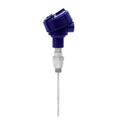
Термопара
Опис
Термопари цієї серії можна комбінувати з великою кількістю конструкцій термогільз. Використання без термогільзи допускається під час застосування фіксованого (зварного) приєднання.
Для термометрів доступні різноманітні можливі комбінації датчика, головки з’єднання, довжини занурення, довжини шийки, приєднання до термогільзи тощо; підходить практично для будь-якого розміру термогільзи.
для подальших погоджень див. сторінку 2
Термопара, модель TC10-0, промислова збірка
Особливості
- Діапазони вимірювань сенсора від -40 ... +1,260 °C [-40 ... +2,300 °F]
- Для монтажу у всі стандартні конструкції захисних гільз
- Пружинно-навантажений вимірювальний вкладиш (змінний)
- Вибухозахищені виконання
- Незмінний (приварений) вимірювальний вкладиш
Питання та відповіді
Який діапазон температур вимірювання має TC10-0?
Залежно від типу термопари — від -40 °C до +1 260 °C; доступні також діапазони з верхньою межею +350 … +1 200 °C.
Які типи термопар і класи допуску доступні?
Типи K, J, E, N і T з класами допуску Class 1, Class 2, Standard та Special.
Чи можна монтувати цю термопару без захисної гільзи?
Так, за умови використання фіксованого (зварного) приєднання вимірювального елемента; зі змінним елементом на пружинному притиску вона призначена для стандартних гільз.
Які варіанти приєднання до процесу передбачені?
½ NPT, ¾ NPT, G ½ B, G ¾ B, M14/M18/M20/M24 x 1.5, а також конічні та паралельні різьби, нипель-муфта-нипель, нероз'ємна шийка й подвійна різьбова бушинг-гайка.
Які вибухозахищені виконання доступні?
Ex i (газ, зони 0/1/2), Ex d (зони 1/2), Ex e, Ex n, а також пилові зони; наприклад ATEX II 1G Ex ia IIC T1…T6 Ga та II 2G Ex db IIB+H2 T6…T4 Gb. Є сертифікації ATEX, IECEx, FM, CSA, EAC, Ex Ukraine, INMETRO, CCC.
Який ступінь захисту та допустима температура навколишнього середовища?
Ступінь захисту IP65, навколишнє середовище від -40 до +80 °C.
Які вихідні сигнали підтримуються?
HART та 4 … 20 mA (з відповідним перетворювачем у клемній головці).
Чим TC10-0 відрізняється від сусідніх моделей серії?
Це базове промислове виконання зі змінним вимірювальним елементом на пружинному притиску для стандартних гільз; комбінування головок, довжин занурення та шийки дозволяє адаптувати його практично під будь-яку гільзу.
| Модель | TC10-0 |
| Сімейство | TC10 |
| Підтип | Thermocouple |
| Діапазон температури | −40…+1260 °C · −40…+1200 °C · −40…+1000 °C · −40…+900 °C · −40…+800 °C · −40…+750 °C · −40…+350 °C · +0…+1260 °C · +0…+870 °C · +0…+760 °C · +0…+370 °C |
| Рівень функціональної безпеки (SIL) | SIL 2 (IEC 61508 / IEC 61511) |
| Технологічне приєднання | ½ NPT¾ NPTG ½ BG ¾ BM14 x 1.5M18 x 1.5M20 x 1.5M24 x 1.5Tapered threadsParallel threadsNipple-union-nipple neck tubeNon-divisible neck tubeDouble threaded hex bushing |
| Темп. процесу | −40…+1260 °C |
| Вихідний сигнал | HART · 4-20 mA |
| Електр. приєднання | Connection head (BS, BSZ-H, KN4-A, KN4-P, 1/4000, 7/8000) |
| Матеріал зонда | Sheathed cable (mineral-insulated cable, MI cable), Sheathed cable (mineral-insulated cable) |
| Темп. навколишнього середовища | −40…+80 °C |
| Ступінь захисту IP | IP65 |
| Сертифікати | CERoHSEACINMETROCCCGOSTKazInMetrMTSCHSBelGIMUkrSEPROUzstandardATEXIECExFMCSAEx UkraineEMC |
| Вибухозахист | Ex i (gas) Zone 0, 1, 2Ex i (dust) Zone 20, 21, 22Ex d (gas) Zone 1, 2Ex d (dust) Zone 21Ex e (gas) Zone 1, 2Ex n (gas) Zone 2Ex t (dust) Zone 21, 22Class I, division 1, group B, C, D, T6 type 4/4XClass II or III, division 1, group E, F, G type 4/4XEx d IIC Gb T6/T5/T4Ex d IIB + H2 Gb T6/T5/T4Ex nA (gas) Zone 2ATEX: II 1G Ex ia IIC T1...T6 Ga, II 2G Ex db IIB+H2 T6...T4 Gb, II 2G Ex eb IIC T1...T6 GbIECEx: Ex ia IIC T1...T6 Ga, Ex db IIB+H2 T6...T4 GbFM: Class I, Div 1, Groups B, C, D, T6; Class II/III, Div 1, Groups E, F, GCSA: Class I, Div 1, Groups B, C, D, T6; Class II/III, Div 1, Groups E, F, GEAC: 0Ex ia IIC T6...T1 Ga, 1Ex d IIC T6...T4 GbEx Ukraine: II 1G Ex ia IIC T1...T6 Ga, II 2G Ex db IIC T6...T4 GbINMETRO: II 1G Ex ia IIC T1...T6 GaCCC: Ex ia IIC T1~T6 Ga, Ex d IIC T4~T6 Gb |
| Тип сенсора | Type K/J/E/N/T |
| Клас сенсора | Class 1, Class 2, Standard, Special |
| Діаметр зонда | 3 mm |
| Захисна гільза | Так |
| Мови datasheet | EN, DE |
| Approval | Explosion protection | |||||
|---|---|---|---|---|---|---|
| Ex i (gas) Zone 0, 1, 2 | Ex i (dust) Zone 20, 21, 22 | Ex d (gas) Zone 1, 2 | Ex d (dust) Zone 21 | Ex e (gas) Zone 1, 2 | Ex n (gas) Zone 2 | |
| ATEX | x | x | x | x | x | x |
| IECEx | x | x | x | x | x | x |
| FM | - | - | x | x | - | - |
| CSA | - | - | x | x | - | - |
| EAC | x | x | x | x | - | x |
| Ex Ukraine | x | x | x | x | - | - |
| INMETRO | x | x | - | - | - | - |
| CCC | x | x | x | x | x | x |
| Type of sensor | Thermocouple per IEC 60584-1 or ASTM E230 Types K, J, E, N,T | |
|---|---|---|
| Hot junction | ■ Ungrounded (standard) ■ Grounded (welded to the sheath) | |
| Marking of the polarity | The colour coding at the positive poles of the instrument decides the correlation of polarity and terminal | |
| Single thermocouple | ||
| Dual thermocouple | ||
| Validity limits of the class accuracy per EN 60584-1 | ||
| Type K | Class 2 Class 1 | -40 ... +1,200 °C [-40 ... +2,192 °F] -40 ... +1,000 °C [-40 ... +1,832 °F] |
| Type J | Class 2 Class 1 | -40 ...+750 °C [-40 ... +1,382 °F] -40 ...+750 °C [-40 ... +1,382 °F] |
| Type E | Class 2 Class 1 | -40 ...+900 °C [-40 ... +1,652 °F] -40 ...+800 °C [-40 ... +1,472 °F] |
| Type N | Class 2 Class 1 | -40 ... +1,200 °C [-40 ... +2,192 °F] -40 ... +1,000 °C [-40 ... +1,832 °F] |
| TypeT | Class 2 Class 1 | -40 ...+350 °C [-40 ...+662 °F] -40 ...+350 °C [-40 ...+662 °F] |
| Validity limits of the class accuracy in accordance with ASTM-E230 | ||
| Type K | Standard Special | 0 ... 1,260 °C [32 ... 2,300 °F] 0 ... 1,260 °C [32 ... 2,300 °F] |
| Type J | Standard Special | 0 ... 760 °C [32 ... 1,400 °F] 0 ... 760 °C [32 ... 1,400 °F] |
| Type E | Standard Special | 0 ... 870 °C [32 ... 1,598 °F] 0 ... 870 °C [32 ... 1,598 °F] |
| Type N | Standard Special | 0 ... 1,260 °C [32 ... 2,300 °F] 0 ... 1,260 °C [32 ... 2,300 °F] |
| TypeT | Standard Special | 0 ... 370 °C [32 ... 698 °F] 0 ... 370 °C [32 ... 698 °F] |
| Model | Material | Cable entry thread size | Ingress protection (max.) 1) IEC/EN 60529 | Cap | Surface | Connection to neck tube | |
|---|---|---|---|---|---|---|---|
| BS | Aluminium | ■ M20 x 1.5 ■ ½NPT | IP65 2) | Flat cover with 2 screws | Blue, painted (RAL 5022) | ■ M24 x 1.5 ■ ½NPT | |
| BS | BSZ, BSZ-K BSZ-H | BSZ-H, Aluminium | BSS ■ M20 x 1.5 ■ ½NPT | BSS-H IP65 2) | BVS BVS Raised hinged cover with cylinder head screw | (NuG) Blue, painted (RAL 5022) | 1/4000 ■ M24 x 1.5 ■ ½NPT |
| Model | Explosion protection | ||||
|---|---|---|---|---|---|
| Without | Ex i (gas) Zone 0, 1, 2 | Ex i (dust) Zone 20, 21, 22 | Ex e (gas) Zone 1, 2 | Ex t (dust) Zone 21, 22 | |
| BS | x | x | - | - | - |
| BSZ-H | x | x | x | x 3) | x 3) |
Переглянути всі (20)
| Model | Material | Cable entry thread size | Ingress protection (max.) 1) IEC/EN 60529 | Cap | Surface | Connection to neck tube | |
|---|---|---|---|---|---|---|---|
| KN4-A | Aluminium | ■ ½NPT ■ M20 x 1.5 | IP65 2) | Screw-on lid | Blue, painted (RAL 5022) | ■ M24 x 1.5 ■ ½NPT | |
| KN4-P 4) | Polypropylene | ½NPT | IP65 2) | Screw-on lid | White | ½NPT | |
| BVC 1/4000 F | Aluminium | ■ ½NPT ■ ¾NPT ■ M20 x 1.5 | IP66 2) | Screw-on lid | Blue, painted (RAL 5022) | ½NPT | |
| 5/6000 1/4000 S | 7/8000 Stainless steel | 7/8000 DIH50 ■ ½NPT ■ ¾NPT ■ M20 x 1.5 | KN4-P andere Anschlussgehäuse IP66 2) | BVC Screw-on lid | Natural finish | ½NPT | |
| 7/8000W | Aluminium | ■ ½NPT ■ ¾NPT ■ M20 x 1.5 | IP66 2) | Screw-on lid | Blue, painted (RAL 5022) | ½NPT | |
| 7/8000 DIH50 7/8000 S | andere Anschlussgehäuse Stainless steel | KN4-P ■ ½NPT ■ ¾NPT ■ M20 x 1.5 | BVC IP66 2) | Screw-on lid | Natural finish | ½NPT |
| Model | Explosion protection | ||||
|---|---|---|---|---|---|
| Without | Ex i (gas) Zone 0, 1, 2 | Ex i (dust) Zone 20, 21, 22 | Ex t (dust) Zone 21, 22 | Ex nA (gas) Zone 2 | |
| KN4-A | x | x | - | - | - |
| KN4-P 4) | x | - | - | - | - |
| 1/4000 F | x | x | - | - | - |
| 1/4000 S | x | x | - | - | - |
| 7/8000W | x | x | - | - | - |
| 7/8000 S | x | x | - | - | - |
| Versions | Vibration-resistant, sheathed cable (mineral-insulated cable, MI cable) | |
|---|---|---|
| Optimal heat transfer | Requirement | ■ Correct measuring insert length ■ Correct measuring insert diameter |
| Bore diameter of the thermowell | Max. 1 mm[0.04 in] larger than measuring insert diameter | |
| Gap width | For joint width > 0.5 mm[> 0.02 in] between thermowell and measuring insert: →Negative impact on heat transfer →Unfavourable response behaviour of the thermometer | |
| Measuring insert diameter Ø d | ■ 3.0mm ■ 6.0mm ■ 8.0mm ■ 1/8 in or 0.125 in [3.17 mm] ■ 3/16 in or 0.188 in [4.75 mm] ■ 1/4 in or 0.250 in [6.35 mm] | |
| Other measuring insert diameters on request | ||
| Insertion length | When fitting the measuring insert into a thermowell, it is very important to determine the correct insertion length (= thermowell length for bottom thicknesses of ≤ 5.5 mm[≤ 0.22 in]). In order to ensure that the measuring insert is firmly pressed down onto the bottom of the thermowell, the insert must be spring-loaded (spring travel: 0 ... 10 mm[0 ... 0.39 in]). | |
| Spring travel | Max. 10 mm[0.39 in] |
| Transmitter models | Model T16 | Model T32 |
|---|---|---|
| Transmitter data sheet | TE 16.01 | TE 32.04 |
| Figure | ||
| Output | ||
| 4 ...20mA | x | x |
| HART ® protocol | - | x |
| Input | ■ Type K ■ Type J ■ Type E ■ Type N ■ TypeT | ■ Type K ■ Type J ■ Type E ■ Type N ■ TypeT |
| Explosion protection | Option | Option |
| Possible mounting positions for transmitters | Model T16 | Model T32 |
|---|---|---|
| BS | ○ | - |
| BSZ-H | ● | ● |
| KN4-A | ○ | ○ |
| KN4-P | ○ | ○ |
| 1/4000 | ○ | ○ |
| 7/8000 | ○ | ○ |
| Ambient and storage temperature | -40 ...+80 °C [-40 ...+176 °F] |
|---|---|
| Vibration resistance | The information on vibration resistance refers to the tip of the measuring insert. →For detailed specifications on the vibration resistance of Pt100 sensors, see Technical information IN 00.17 at www.wika.de. |
| Standard | 6 g peak-to-peak, wire-wound measuring resistor or thin film |
| Option | ■ Vibration-resistant probe tip, max. 20 g peak-to-peak, thin-film measuring resistor ■ Highly vibration-resistant probe tip, max. 50 g peak-to-peak, thin-film measuring resistor |
| First index number | Degree of protection / Short description | Test parameters |
|---|---|---|
| Degrees of protection against solid foreign bodies (defined by the 1st index number) | ||
| 5 | Dust-protected | Per IEC/EN 60529 |
| 6 | Dust-tight | Per IEC/EN 60529 |
| Degrees of protection against water (defined by the 2nd index number) | ||
| 4 | Protected against splash water | Per IEC/EN 60529 |
| 5 | Protected against water jets | Per IEC/EN 60529 |
| 6 | Protected against strong water jets | Per IEC/EN 60529 |
| 7 1) | Protected against the effects of temporary immersion in water | Per IEC/EN 60529 |
| 8 1) | Protected against the effects of permanent immersion in water | As agreed upon |
| Model | Data sheet | Illustration |
|---|---|---|
| TW10 | TW95.10 | |
| TW15 | TW95.15 | |
| TW20 | TW95.20 | |
| TW25 | TW95.25 | |
| TW30 | TW95.30 | |
| TW31 | TW95.31 | |
| TW50 | TW95.50 | |
| TW55 | TW95.55 |
| Logo | Description | Country |
|---|---|---|
| EU declaration of conformity | European Union |
| Logo | Description | Country | |
|---|---|---|---|
| EU declaration of conformity ATEX directive Hazardous areas - Ex i Zone 0 gas Zone 1 mounting to zone 0 gas Zone 1 gas Zone 20 dust Zone 21 mounting to zone 20 dust Zone 21 dust - Ex d Zone 1 gas Zone 1 gas Zone 21 dust - Ex e Zone 1 gas Zone 2 gas Zone 21 dust Zone 22 dust | II 1G Ex ia IIC T1 ...T6 Ga II 1/2G Ex ia IIC T1 ...T6 Ga/Gb II 2G Ex ia IIC T1 ...T6 Gb II 1D Ex ia IIIC T125 ...T65 °C Da II 1/2D Ex ia IIIC T125 ...T65 °C Da/Db II 2D Ex ia IIIC T125 ...T65 °C Db II 2G Ex db IIB + H2T6 ...T4 Gb II 2G Ex db IIC T6 ...T4 Gb II 2D Ex tb IIIC T85 °C Db IP66 II 2G Ex eb IIC T1 ...T6 Gb 3) II 3G Ex ec IIC T1 ...T6 Gc X II 2D Ex tb IIICTX °C Db 3) II 3D Ex tc IIICTX °C Dc X II 3G Ex nA IIC T1 ...T6 Gc X II 3D Ex tc IIICTX °C Dc X | European Union | |
| - Ex n Zone 2 gas Zone 22 dust IECEx - in combination with ATEX Hazardous areas - Ex i Zone 0 gas Zone 1 mounting to zone 0 gas Zone 1 gas Zone 20 dust Zone 21 mounting to zone 20 dust Zone 21 dust - Ex d Zone 1 gas Zone 1 gas Zone 21 dust - Ex e 2) Zone 1 gas Zone 2 gas Zone 21 dust Zone 22 dust - Ex n 2) Zone 2 gas | Ex ia IIC T1 ...T6 Ga Ex ia IIC T1 ...T6 Ga/Gb Ex ia IIC T1 ...T6 Gb Ex ia IIIC T125 ...T65 °C Da Ex ia IIIC T125 ...T65 °C Da/Db Ex ia IIIC T125 ...T65 °C Db Ex db IIB + H2T6 ...T4 Gb Ex db IIC T6 ...T4 Gb Ex tb IIIC T85 °C Db IP66 Ex eb IIC T1 ...T6 Gb 3) Ex ec IIC T1 ...T6 Gc X Ex tb IIICTX °C Db 3) Ex tc IIICTX °C Dc X Ex nA IIC T1 ...T6 Gc X Ex tc IIICTX °C Dc X | International | |
| Zone 22 dust FM Hazardous areas - Ex d (XP) Division 1 gas Division | Class I, division 1, group B, C, D, T6 type 4/4X | USA and Canada | |
| 1 dust CSA Safety (e.g. electr. safety, overpressure, ...) Hazardous areas - Ex d (XP) Division 1 gas | Class II or III, division 1, group E, F, Gtype 4/4X Class I, division 1, groups B, C, D, T6 type 4/4X | USA and Canada |
| Logo | Description | Country |
|---|---|---|
| EAC (option) Hazardous areas | Eurasian Economic Community | |
| - Ex n Zone 2 gas 2Ex nA IIC T6 ...T1 Gc X Ex Ukraine Hazardous areas - Ex i Zone 0 gas II 1G Ex ia IIC T1 ...T6 Ga Zone 1 mounting to zone 0 gas II 1/2G Ex ia IIC T1 ...T6 Ga/Gb | Ukraine | |
| Zone 1 mounting to zone 0 gas II 1/2G Ex db IIC T6 ...T4 Ga/Gb Zone 21 dust II 2D Ex tb IIIC T85 °C Db INMETRO Hazardous areas - Ex i Zone 0 gas II 1G Ex ia IIC T1 ...T6 Ga Zone 1 mounting to zone 0 gas II 1/2G Ex ia IIC T1 ...T6 Ga/Gb Zone 20 dust Ex ia IIIC T125 ...T65 °C Da Zone 21 mounting to zone 20 dust Ex ia IIIC T125 ...T65 °C Da/Db 3) | Brazil | |
| CCC Hazardous areas - Ex i Zone 0 gas Ex ia IIC T1 ~ T6 Ga Zone 1 gas Ex ia IIC T1 ~ T6 Gb Zone 1 mounting to zone 0 gas Ex ia IIC T1 ~ T6 Ga/Gb Zone 2 gas Ex ic IIC T1 ~ T6 Gc Zone 21 dust Ex iaD 21 T65/T95/T125°C - Ex d Zone 1 gas Ex d IIB+H2 T4~T6 Gb Zone 1 gas Ex d IIC T4~T6 Gb Zone 21 dust Ex tD A21 IP66 T85°C | China | |
| GOST Metrology, measurement technology | Russia | |
| KazInMetr | Kazakhstan | |
| - | Metrology, measurement technology MTSCHS Permission for commissioning | Kazakhstan |
| BelGIM Metrology, measurement technology | Belarus | |
| - | UkrSEPRO Metrology, measurement technology | Ukraine |
| Uzstandard | ||
| Metrology, measurement technology | Uzbekistan |
| Certification type | Measurement accuracy | Material certificate |
|---|---|---|
| 2.2 test report | x | x |
| 3.1 inspection certificate | x | x |
| DAkkS calibration certificate | x | - |
| Model | Description D |
|---|---|
| PIH-L | Connection head with flat screw-on lid |
| PIH-H | Connection head with high screw-on lid |
| PIH-W | Connection head with high screw-on lid and window |
| PIR-L | Connection head with flat screw-on lid, pipe or wall mounting |
| PIR-H | Connection head with high screw-on lid, pipe or wall mounting |
| PIR-W | Connection head with high screw-on lid and window, pipe or wall mounting E |
| Materials | ||
|---|---|---|
| Lower part of the case PIX-X Explosion CONNECTION HEAD | Aluminium die-casting EN AC-43500 AlSi10MnMg / AA 365.0; copper content ≤ 0,05% (low copper) drawing number 14654707.01 | |
| Screw-on lid scale 1:1 | Aluminium die-casting EN AC-43500 AlSi10MnMg / AA 365.0; copper content ≤ 0,05% (low copper) F reference DR 08 sheets 1 / 1 | |
| Window Check indicator size | Glass ALEXANDER WIEGAND SE & Co. KG comments | |
| Sealing language | ■ EPDM -60 ...+90 °C [-76 ... 194 °F] ■ MVQ-60 ...+110°C [-76 ... 230 °F], on request ■ FKM -20 ...+110°C [-4 ... 230 °F], on request www.wika.com D-63911 Klingenberg DEKLI1_EN_A4M_T00 26.04.2023 [inch] | |
| Case surface | ||
| Colour | Lower body | WIKA product grey RAL 7035 |
| Screw-on lid | WIKA product blue RAL 5022 | |
| Coating | ■ PE/PU (polyester/polyurethane) powder coating ■ 90 ±40 µm thickness ■ Electrically conductive per IEC 60243-1:2013 ■ The painted test objects / surfaces were subjected to a salt mist and condensation test per C5-M, per ISO 12944-6.The evaluation per ISO 4624, ISO 4628-2/-3/- 4/-5/-6, as well as the scored areas per ISO 12994 A.2 showed no significant abnormalities. ■ Cross-cut:GT 0 (...1) per ISO 2409:2013 - 1c or 2a |
| Basic information | |
|---|---|
| Features | ■ Impact resistance of the window per IEC 60079-0:2017 point 26.4.2 ■ Pressure containment of case per IEC 60079-1:2014 point 15.2.3.2 ■ UV resistance per ISO 4892-3:2016 procedure A, cycle 3 |
| Weight | |
| Case with flat screw-on lid | ≤ 0.85 kg [≤ 1,9 lbs] |
| Case with high screw-on lid | ≤ 1.0 kg [≤ 2,2 lbs] |
| Case head with high screw-on lid and window | ≤ 1.1 kg [≤ 2,4 lbs] |
| Head version for direct mounting on an electrical thermometer | Left Input A | Right Input B | Bottom, to neck tube Input C |
|---|---|---|---|
| PIH-L, PIH-H, PIH-W | M20 x 1.5 | Closed | M20 x 1.5, 1/2 NPT, 3/4 NPT |
| M20 x 1.5 | M20 x 1.5 | M20 x 1.5, 1/2 NPT, 3/4 NPT | |
| 1/2 NPT | Closed | M20 x 1.5, 1/2 NPT, 3/4 NPT | |
| 1/2 NPT | 1/2 NPT | M20 x 1.5, 1/2 NPT, 3/4 NPT | |
| 3/4 NPT | Closed | 1/2 NPT, 3/4 NPT |
Не знайшли відповіді у документації? Інженер відповість впродовж робочого дня.
Запитати інженера →