
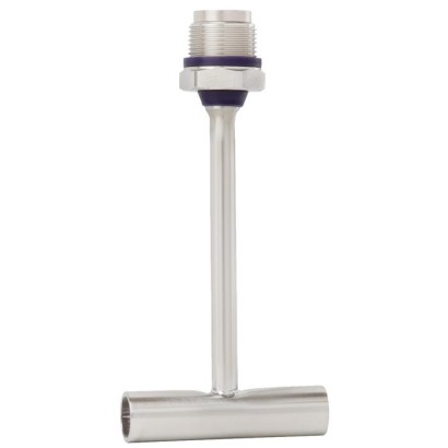
Protection tube
Description
The patented protection tube model TW61 (patent, property right: DE 102010037994 and US 12 897.080) is used to adapt a model TR21-B or TR22-B resistance thermometer to the process and to protect the sensor from harsh process conditions.
To integrate it into the process, the protection tube is directly orbitally welded into a pipeline. The connection ends are smooth and prepared for orbital welding.
for further approvals, see page 5
Fig. left: G 3/8 thread for model TR21-B Fig. right: M24 threaded connection for model TR22-B
Options: Sealing combination at neck tube
The measuring insert can be withdrawn together with the connection head. This makes it possible to calibrate the thermometer with the entire measuring chain, on-site, without disconnecting the electrical connections. In addition, this avoids having to open the process, and thus the risk of contamination is minimised.
In combination with a model TR22-B resistance thermometer, the swivel connection of the connection head or the display can be loosened and turned to the desired orientation.
Special features
- Materials and surface finish quality in accordance with the standards of hygienic designs
- Self-draining
- Dead-space minimised
- For orbital welding
Build a TW61 for your task
The article number is assembled automatically. If unsure — ask an engineer; we'll match the line's parameters.
- Protection tubeTW61 - flow-through housing (prepared for orbital welding)
- Process connectionEN 10357-A (DIN 11850) and DIN 11866-A
- Size / DesignDN 10 (tube 13 x 1,5)
- Material wetted parts—
- Instrument Connection—
- Insertion length [U1 or l1]6 mm
- Neck tube diameter9 mm
- Neck tube length [M]—
- Sealing—
- CertificatesWithout
Finish your configuration
Select every option to submit the request.
| Model | TW61 |
| Product family | TW |
| Subcategory | Protection tube |
| Temperature ranges | −50…+150 °C |
| Process connection | G 3/8 threadM24 x 1.5 swivel connectionM24 x 1.5 |
| Process temperature | −50…+150 °C |
| Probe material | Stainless steel 1.4435, Stainless steel 316L |
| Thermowell material | Stainless steel 1.4435, Stainless steel 316L |
| Ambient temperature | −40…+85 °C |
| IP rating | IP68 |
| Certifications | 3-AEHEDGCEPEDEAC |
| Probe diameter | 4.8 mm |
| Thermowell | Yes |
| Thermowell form | flow-through housing, angular housing |
| Datasheet languages | EN, DE |
| Basic information | ||
|---|---|---|
| Version | ■ G3/8, male thread, suitable for thermometer model TR21-B ■ M24 x 1.5, swivel connection, suitable for thermometer model TR22-B | |
| Material (wetted) | ■ DIN 11866 row A (metric) ■ DIN 11866 row B (ISO) | Stainless steel 1.4435 |
| DIN 11866 row C, ASME BPE | Stainless steel 316L | |
| Other materials on request | ||
| Process connection | ||
| Protection tube form | ■ Flow-through housing ■ Angular housing | |
| Protection tube diameter | Ø=4.8 mm[0.19 in] | |
| Surface roughness | DIN 11866 row A, B | ■ Ra < 0.8 μm ■ Ra < 0.4 μm, electropolished |
| DIN 11866 row C, ASME BPE | ■ Ra < 0.51 μm (SF1) ■ Ra ≤ 0.38 µm, electropolished (SF4) | |
| Others on request | ||
| Operating conditions | ||
| Medium temperature range | -50 ...+150 °C [-58 ...+302 °F] | |
| Ambient temperature range | -40 ...+85 °C [-40 ...+185 °F] | |
| Storage temperature range | -40 ...+85 °C [-40 ...+185 °F] | |
| Neck tube length | For assembly with a resistance thermometer, the neck tube length is matched to the following insertion lengths. The inventory of the measuring inserts, particularly for larger plants, is reduced through the use of uniform measuring insert lengths, even for different nominal widths of pipes. | |
| Model TR21-B | Insertion length (A-length) of 60 mm[2.36 in] | |
| Model TR22-B | ■ Measuring insert length of 150 mm[4.92 in] 1) ■ Insertion length (A-length) of 125 mm[4.92 in] 1) | |
| Further neck tube lengths on request |
| Nominal width | pressure in Outer diam- eter of 11612037.01 | pipe Pipe schedule | Tube length | Protec - tion tube | Neck tube length | ||||
|---|---|---|---|---|---|---|---|---|---|
| bar | insertion | TR21-B | TR22-B | ||||||
| DN / OD | PS 1) 2) | Ø D | s | TL | length U 1 | M | M | ||
| 10 | 25 | 13 | 1.5 | 70 | 6 | 51 | 129 | ||
| 15 | 25 | 19 | 1.5 | 70 | 9 | 48 | 126 | ||
| 20 | 25 | 23 | 1.5 | 80 | 11 | 46 | 124 | ||
| 25 | 25 | 29 | 1.5 | 100 | 18 | 39 | 117 | ||
| 32 | 25 | 35 | 1.5 | 110 | 18 | 39 | 117 | ||
| 40 | 25 | 41 | 1.5 | 120 | 18 | 39 | 117 | ||
| 50 | 25 | 53 | 1.5 | 160 | 30 | 27 | 105 | ||
| 65 | 16 | 70 | 2.0 | 210 | 30 | 27 | 105 | ||
| 80 | 16 | 85 | 2.0 | 260 | 45 | 12 | 90 | ||
| 100 | 12.5 | 104 | 2.0 | 310 | 45 | 12 | 90 | ||
| 8 (13.5) 10 (17.2) | 25 | 13.5 | 1.6 | 64 | 6 | 51 | 129 | ||
| 25 | 17.2 | 1.6 | 68 | 9 | 48 | 126 | |||
| 15 (21.3) | 25 | 21.3 | 1.6 | 72 | 11 | 46 | 124 | ||
| 20 (26.9) | 25 | 26.9 | 1.6 | 110 | 11 | 46 | 124 | ||
| 25 (33.7) | 25 | 33.7 | 2.0 | 120 | 18 | 39 | 117 | ||
| 32 (42.4) | 25 | 42.4 | 2.0 | 130 | 18 | 39 | 117 | ||
| 40 (48.3) | 25 | 48.3 | 2.0 | 130 | 18 | 39 | 117 | ||
| 50 (60.3) | 25 | 60.3 | 2.0 | 180 | 30 | 27 | 105 | ||
| 65 (76.1) | 16 | 76.1 | 2.0 | 220 | 30 | 27 | 105 | ||
| 80 (88.9) | 16 | 88.9 | 2.3 | 260 | 45 | 12 | 90 | ||
| 1/2" | 13.8 | 12.7 | 1.65 | 95.2 | 6 | 51 | 129 | ||
| 3/4" | 13.8 | 19.05 | 1.65 | 101.6 | 9 | 48 | 126 | ||
| 1" | 13.8 | 25.4 | 1.65 | 108.0 | 11 | 46 | 124 | ||
| 1 1/2" | 13.8 | 38.1 | 1.65 | 120.6 | 18 | 39 | 117 | ||
| 2" | 13.8 | 50.8 | 1.65 | 146.0 | 18 | 39 | 117 | ||
| 2 1/2" | 13.8 | 63.5 | 1.65 | 158.8 | 30 | 27 | 105 | ||
| 3" | 13.8 | 76.2 | 1.65 | 171.4 | 30 | 27 | 105 | ||
| 4" | 13.8 | 101.6 | 2.11 | 209.6 | 45 | 12 | 90 |
| Nominal width of pipe | Nominal pressure in bar | Outer diam- eter of pipe | Pipe schedule | Tube length | Protection tube inser - tion length | Neck tube length | |||
|---|---|---|---|---|---|---|---|---|---|
| PS 1) 2) | Ø D | s | TL | L 1 | U 1 | TR21-B | TR22-B | ||
| DN / OD DIN 11866 row A or metric | 10 | 13 | 1.5 | 35 | 55 | M 43 | M 121 | ||
| 15 | 25 25 | 19 | 1.5 | 35 | 55 | 14 18 | 39 | 117 | |
| 20 | 25 | 23 | 1.5 | 63 | |||||
| 40 | 18 | 39 | 117 | ||||||
| 25 | 25 | 29 | 1.5 | 50 | 77 | 30 | 27 | 105 | |
| 11866 row A or metric | 32 40 ® | 25 | 35 | 1.5 | 55 | 87 | 30 | 27 | 105 |
| DIN | 25 | 41 | 1.5 | 60 | 97 | 30 | 27 | 105 | |
| 50 | 25 | 53 | 1.5 | 80 | 126 | 30 | 27 | 105 | |
| 65 | 16 | 70 | 2.0 | 105 | 165 | 45 | 12 | 90 | |
| 80 | 16 | 85 | 2.0 | 130 | 201 | 45 | 12 | 90 | |
| JANUARY 2019 TYPE EL CLASS I | 100 | 12.5 | 104 | 2.0 | 155 | 241 | 45 | 12 | 90 |
| DIN 11866 row B or ISO | 8 (13.5) | 25 | 13.5 | 1.6 | 32 | 55 | 14 | 43 | 121 |
| 10 (17.2) | 25 | 17.2 | 1.6 | 34 | 55 | 16 | 41 | 119 | |
| 15 (21.3) | 25 | 21.3 | 1.6 | 36 | 58 | 18 | 39 | 117 | |
| 20 (26.9) | 25 | 26.9 | 1.6 | 55 | 81 | 30 | 27 | 105 | |
| DIN 11866 row B or ISO | 25 (33.7) | 25 | 33.7 | 2.0 | 60 | 91 | 30 | 27 | 105 |
| 32 (42.4) | 25 | 42.4 | 2.0 | 65 | 102 | 30 | 27 | 105 | |
| 40 (48.3) | 25 | 48.3 | 2.0 | 65 | 108 | 30 | 27 | 105 | |
| 50 (60.3) | 25 | 60.3 | 2.0 | 90 | 145 | 45 | 12 | 90 | |
| JANUARY 2019 TYPE EL CLASS I | 65 (76.1) | 16 | 76.1 | 2.0 | 110 | 173 | 45 | 12 | 90 |
| 80 (88.9) | 16 | 88.9 | 2.3 | 130 | 203 | 45 | 12 | 90 | |
| DIN 11866 row C 1/2" | 13.8 | 12.7 | 1.65 | 47.6 | 71 | 14 | 43 | 121 | |
| or ASME BPE 3/4" | 13.8 | 19.05 | 1.65 | 50.8 | 71 | 18 | 39 | 117 | |
| 1" | 13.8 | 25.4 | 1.65 | 54.0 | 79 | 18 | 39 | 117 | |
| row | 1 1/2" ® | 13.8 | 38.1 | 1.65 | 60.3 | 94 | 30 | 27 | 105 |
| 11866 ASME BPE | 2" | 13.8 | 50.8 | 1.65 | 73.0 | 118 | 30 | 27 | 105 |
| 2 1/2" | 13.8 | 63.5 | 1.65 | 79.4 | 134 | 45 | 12 | 90 | |
| C or | 3" | 13.8 | 76.2 | 1.65 | 85.7 | 150 | 45 | 12 | 90 |
| 4" 2019 EL | 13.8 | 101.6 | 2.11 | 104.8 | 190 | 45 | 12 | 90 |
| Logo | Description | Region |
|---|---|---|
| EU declaration of conformity | European Union |
View all (7)
| Logo | Description | Region |
|---|---|---|
| EAC | Eurasian Economic Com - munity | |
| Pressure Equipment Directive | ||
| - | MChS Permission for commissioning | Kazakhstan |
| ® | 3-A 1) Sanitary Standard Flow-through housing: yes, from DIN 11866 row A:DN 20 ... 100 DIN 11866 row B:DN 20 ... 80 DIN 11866 row C:DN 1" ... 4" Angular housing: yes, from DIN 11866 row A:DN 32 ... 100 DIN 11866 row B:DN 32 ... 80 | USA |
| EHEDG 1) Hygienic Equipment Design Flow-through housing: yes, for all dimensions Angular housing: yes, from DIN 11866 row A:DN 32 ... 100 DIN 11866 row B:DN 32 ... 80 | European Union |
| Certificates | ■ 2.2 test report per EN 10204 (e.g. state-of-the-art manufacturing, material proof, indica- tion accuracy) ■ 3.1 inspection certificate per EN 10204 (e.g. material proof for wetted metal parts, indication accuracy, calibration certificate) ■ Manufacturer's declaration regarding regulation (EC) 1935/2004 ■ Certificate of the surface roughness of wetted components ■ Hygiene certificate |
|---|
| Patent number | Description |
|---|---|
| DE 102010037994 US 12 897.080 | Dead-space free welding nipple |
| GM 000984349 | Case with easily cleanable twist crown, integrated into the case cap (option: with BVS head) |
Couldn't find the answer in the documentation? An engineer will reply within a business day.
Ask an engineer →12 standard articles of family TW
If you know the code — pick directly. If not — use the configurator in mode “01”.