
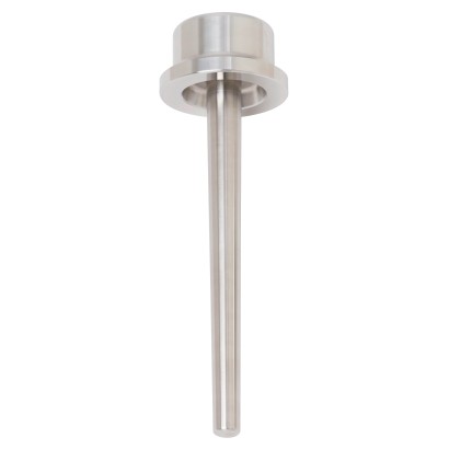
Thermowell with hub connection
Description
The TW32 series of thermowells with hub connection are designed for use with a wide range of electrical and mechanical WIKA thermometers. Their robust design makes them the preferred solution for applications in the petrochemical industry as well as in the oil and gas industry especially where only limited mounting space is available.
Thermowells assume a central function within temperature measuring locations: They separate the process space from the environment, thus protecting both the operating personnel and the environment and protecting the temperature probe from aggressive media, high pressures and strong flows. At the same time, they enable the replacement of the thermometer during operation.
Special features
- Suitable for hub connections of numerous manufacturers
- Solid-machined version without weld seam
- Much smaller size than comparable conventional flanges
- High leakage safety through metal sealing
- Best fatigue strength for wake frequency calculations in accordance with ASME PTC 19.3 TW-2016
| Model | TW32 |
| Product family | TW |
| Subcategory | Thermowell |
| Process connection | Hub connection1½ NPT female threadM20 x 1.5 female thread |
| Process temperature | ≤ +650 °C |
| Thermowell material | Stainless steel 316/316L, Stainless steel 304/304L, A105, Stainless steel 1.4571, Alloy C4, Alloy C276, Alloy 400, Alloy 625, A182 F51, A182 F55 |
| Weight | 2.25 kg |
| Certifications | NACE MR01/75NACE MR01/03 |
| Probe length | 610 mm |
| Probe diameter | 6.6 mm |
| Thermowell | Yes |
| Thermowell form | Tapered, straight |
| Datasheet languages | EN, DE |
| Max. process temperature, process pressure | |
|---|---|
| Thermowell design | ■ Dimensions ■ Material |
| Process conditions | ■ Flow rate ■ Medium density ■ Medium temperature ■ Process pressure |
| Hydrostatic pressure test | ■ External pressure to 650 bar [9,427 psi], 3 min ■ Internal pressure to 1,165 bar [16,897 psi], 3 min |
| Wake frequency calculation | Calculation of individual thermowells in accordance with ASME PTC 19.3 TW-2016 minimises the risk of dynamic damage that can be caused by the vortex shedding of a Kármán vortex street (Vortex Induced Vibration; VIV). In addition, the static loads due to lateral flow and the process pressure are calculated depending on the temperature. The calculation can be carried out independently using an online tool or as a WIKA engineered service (subject to charges). |
| → For further information, see technical information IN 00.15 'Wake frequency calcula- tion'. | |
| Insertion length U WFC | The groove depth G must be added to the insertion length U. U WFC = U + G Example WIKA hub size 2W20 with U = 300 mm: U WFC = 300 mm (11.811") + 17.5 (0.688") = 317.5 mm (12.5") |
| WIKA Hub size | Dimensions in mm [in] | |||||||
|---|---|---|---|---|---|---|---|---|
| H | F | G | Ø B | Ø Q | Ø V 1) | Ø Bd | Ø P | |
| 1.5W11 | 54 [2.13] | 12.7 [0.5] | 14.3 [0.56] | ■ 6.6 [0.24] | 25 [0.98] | 19 [0.75] | 60.3 [2.38] | 79.4 [3.13] E |
| 1.5W14 | 54 [2.13] REVISION | 11.1 [0.44] | 17.5 [0.69] | ■ 8.5 [0.36] ■ 9.8 [0.39] | 25 [0.98] | 19 [0.75] | 60.3 [2.38] | 79.4 [3.13] |
| 2W14 | 51 [2] | 11.1 [0.44] | 17.5 [0.69] | 30 [1.18] | 19 [0.75] | 73 [2.88] | 92 [3.63] | |
| 2W20 | 51 [2] | 11.1 [0.44] | 17.5 [0.69] | 30 [1.18] | 19 [0.75] | 73 [2.88] | 92 [3.63] | |
| WB20 | 70 [2.75] KLI-ZCHG | 15.9 [0.63] KONISCH | 18 [0.71] | 30 [1.18] | 19 [0.75] drawing number | 95.3 [3.75] | 120.7 [4.75] |
| WIKA Hub size | Weight in kg [lb] 1:1 released 23.10.23 ROEDERM DR 08 sheets 1 / 1 raw nominal | ||
|---|---|---|---|
| U = 200 mm [7.87 in] part 11.09.23 01 first created BORSEB | U = 400 mm [15.75] Check indicator | U = 600 mm [23.62 in] D-63911 Klingenberg ALEXANDER WIEGAND SE & Co. KG comments | |
| 1.5W11 | 2.25 [4.9] by WIKA 11.09.2023 | 3.1 [6.8] language GER/ENG | 4 [8.8] www.wika.com |
| 1.5W14 | 2.15 [4.7] | 3 [6.6] | 3.9 [8.5] DEKLI1_EN_A4M_T00 26.04.2023 |
| 2W14 | 2.65 [5.8] | 3.5 [7.7] | 4.4 [9.6] |
| 2W20 | 2.45 [5.4] | 3.3 [7.2] | 4.2 [9.2] |
| WB20 | 5.44 [11.98] | 6.34 [13.9 ] | 7.24 [15.9] |
| WIKA hub size | Technically compatible with the following connection types from third-party companies 1) | ||
|---|---|---|---|
| Grayloc, Galperti and G-Lok | Techloc | Destec G-Range | |
| 1.5W11 | 1.5 GR11 | 1-1/2in/11 | G1½-11 |
| 1.5W14 | 1.5 GR14 | 1-1/2 in/14 | G1½-14 |
| 2W14 | 2 GR14 | 2in/14 | G2-14 |
| 2W20 | 2 GR20 | 2in/20 | G2-20 |
| WB20 | H20 | H20in | - |
View all (6)
| NACE | ■ MR01/75 via subsupplier certificate ■ MR01/03 via subsupplier certificate ■ MR01/75 via hardness test ■ MR01/03 via hardness test |
|---|---|
| Bore centrality | ■ X-ray test per DIN EN ISO 17636-1&2 / Assessment per DIN EN ISO 5817 ■ X-ray test per ASME Sec.V. Article 2, Latest ed. / Assessment per ASME B31.3 ■ Ultrasonic test |
| Tip thickness | ■ X-ray test per DIN EN ISO 17636-1 & 2 / Assessment per DIN EN ISO 5817 ■ X-ray test per ASME Sec.V. Article 2, Latest ed. / Assessment per ASME B31.3 |
| Certificates | ■ 2.2 test report per EN 10204 (e.g. state-of-the-art manufacturing, material proof, indica- tion accuracy) ■ 3.1 inspection certificate per EN 10204 (e.g. material proof for wetted metal parts, indi - cation accuracy, calibration certificate) ■ 3.2 inspection certificate |
|---|
Couldn't find the answer in the documentation? An engineer will reply within a business day.
Ask an engineer →