
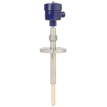
WIKA · Temperature measurement · Family TC83
Sapphire-design thermocouple
High-temperature thermocouple with sapphire protection tube for aggressive processes up to 1,700 °C, suitable for hydrogenous atmospheres and toxic media.
Range
-40…1700 °C
Output
HART · 4-20mA
Protection
IP66
CERoHSEACATEXIECExREACHEx ia IIC T* Gb/-1Ex d IIC T6...T1 Gb X1Ex ia IIC T6...T1 Gb XII 2/-G Ex db IIC T6 ... T1 Gb/-II 2/- G Ex ia IIC T* Gb/-Ex db IIC T6 ... T1 Gb/-Ex db IIC T6...T1 GbEx ia IIC T* GbEx ia IIIC T* DbII 2/-G Ex db IIC T6 ...T1 Gb/-II 2/-G Ex db IIC Gb/-II 2/-G Ex ia IIC T* Gb/-II 2/-D Ex ia IIC T* Db/-II 2/-G Ex ia IIC Gb/-II 2/-D Ex ia IIC Db/-Ex db IIC T6 ...T1 Gb/-Ex db IIC Gb/-Ex ia IIC T* Db/-Ex ia IIC Gb/-Ex ia IIC Db/-Ex ia IIC T135°C Db X
Price
On request
Depends on configuration
Description
This high-temperature thermocouple with a gas-tight sapphire protection tube has been specifically developed for use in hydrogenous atmosphere.
Through the monocrystalline structure, the sapphire protects the noble metal of the thermocouple from poisonous toxic media in the aggressive process atmosphere.
Hermetically sealed junctions prevent toxic gases from being able to escape the reactor.
The high temperatures in the process place very high demands on protection tubes and thermocouples.
These process conditions often lead to shutdowns and interruptions in operation.
For further approvals, see page 8
Special features
- Cost saving by non-purge system
- Reduction of unplanned downtimes
- Increased safety against escape of toxic media through double sealing system
- High variance of thermowell / protection tube materials
- High process safety with processes up to 1,700 °C [3,092 °F]
Identification
| Model | TC83 |
| Subcategory | Sapphire-design thermocouple |
Measuring range
| Temperature ranges | −40…+1200 °C · −40…+1000 °C · −40…+750 °C · +0…+1600 °C · +600…+1700 °C · +870…+1700 °C · −40…+900 °C · −40…+800 °C · +0…+1260 °C · +0…+1480 °C |
Accuracy
| Safety integrity level (SIL) | SIL 2 |
Process conditions
| Process connection | ASME 1.5" ... 6"EN 1092-1 DN40 ... DN100ASME 1.5" to 6"EN 1092-1 DN40 to DN100ASME 1.5...6"150...1,500 lbPN40...PN100 |
| Process temperature | +0…+1700 °C |
Electrical characteristics
| Output signal | HART · 4-20mA |
| Power supply | Not specified |
| Electrical connection | M20 x 1.5, ½ NPT, ¾ NPT |
Materials
| Probe material | Stainless steel 310, 446, Alloy 600, Sapphire, Ceramic, Ceramic C530, Ceramic C610, Ceramic C799, Silicon carbide (Hexoloy®) |
| Thermowell material | Ceramic C530, Ceramic C610, Ceramic C799, Silicon carbide (Hexoloy), Ceramic, Stainless steel (outer), Silicon carbide (Hexoloy®) |
Operating environment
| Ambient temperature | −60…+80 °C |
| IP rating | IP66 |
Certifications and approvals
| Certifications | CERoHSEACATEXIECExREACH |
| Explosion protection | Ex ia IIC T* Gb/-1Ex d IIC T6...T1 Gb X1Ex ia IIC T6...T1 Gb XII 2/-G Ex db IIC T6 ... T1 Gb/-II 2/- G Ex ia IIC T* Gb/-Ex db IIC T6 ... T1 Gb/-Ex db IIC T6...T1 GbEx ia IIC T* GbEx ia IIIC T* DbII 2/-G Ex db IIC Gb/-II 2/-D Ex ia IIC T* Db/-II 2/-G Ex ia IIC Gb/-II 2/-D Ex ia IIC Db/-Ex db IIC Gb/-Ex ia IIC T* Db/-Ex ia IIC Gb/-Ex ia IIC Db/-Ex ia IIC T135°C Db X |
Additional details
| Sensor type | Type K/J/E/R/S/B |
| Sensor class | Class 1, Class 2, Class 3, Standard, Special |
| Probe length | 1000 mm |
| Probe diameter | 25 mm |
| Thermowell | Yes |
| Thermowell form | fabricated |
| Datasheet languages | EN, DE |
Tables from datasheet
Measuring element 3166849.03
| Type of measuring element | Thermocouple per IEC 60584-1 or ASTM E230 Types K, J, E, R, S, B |
|---|---|
| Probe tip design (hot junction) | 3 |
| Design with outer and inner protection tube | ■ Insulation rod ■ Welded thermocouple (hot junc - tion) ■ Sapphire inner protection tube ■ Outer protection tube |
| Marking of the polarity | 2 The colour code at the positive poles of the instrument decides the correlation of polarity and terminal. |
Measuring element
| Single thermocouple | ||
|---|---|---|
| Dual thermocouple | ||
| Validity limits of the class accuracy in accordance with IEC 60584-1 | ||
| Type K | Class 2 | -40 ... +1,200 °C [-40 ... +2,192 °F] |
| Class 1 | -40 ... +1,000 °C [-40 ... +1,832 °F] | |
| Type J | Class 2 | -40 ...+750 °C [-40 ... +1,382 °F] |
| Class 1 | -40 ...+750 °C [-40 ... +1,382 °F] | |
| Type E | Class 2 | -40 ...+900 °C [-40 ... +1,652 °F] |
| Class 1 | -40 ...+800 °C [-40 ... +1,472 °F] | |
| Type R | Class 2 | 0 ... 1,600 °C [32 ... 2,912 °F] |
| Class 1 | 0 ... 1,600 °C [32 ... 2,912 °F] | |
| Type S | Class 2 | 0 ... 1,600 °C [32 ... 2,912 °F] |
| Class 1 | 0 ... 1,600 °C [32 ... 2,912 °F] | |
| Type B | Class 3 | 600 ... 1,700 °C [1,112 ... 3,092 °F] |
| Class 1 | 600 ... 1,700 °C [1,112 ... 3,092 °F] | |
| Validity limits of the class accuracy in accordance with ASTM E230 | ||
| Type K | Standard | 0 ... 1,260 °C [32 ... 2,300 °F] |
| Special | 0 ... 1,260 °C [32 ... 2,300 °F] | |
| Type J | Standard | 0 ... 760 °C [32 ... 1,400 °F] |
| Special | 0 ... 760 °C [32 ... 1,400 °F] | |
| Type E | Standard | 0 ... 870 °C [32 ... 1,598 °F] |
| Special | 0 ... 870 °C [32 ... 1,598 °F] | |
| Type R | Standard | 0 ... 1,480 °C [32 ... 2,696 °F] |
| Special | 0 ... 1,480 °C [32 ... 2,696 °F] | |
| Type S | Standard | 0 ... 1,480 °C [32 ... 2,696 °F] |
| Special | 0 ... 1,480 °C [32 ... 2,696 °F] | |
| Type B | Standard | - |
| Special | 870 ... 1,700 °C [1,598 ... 3,092 °F] |
| Model | Material | Cable inlet thread size | Ingress protection (max.) 1) 2) IEC/EN 60529 | Cap | Surface | Connection to neck tube | |
|---|---|---|---|---|---|---|---|
| 1/4000 | 1/4000 F | Aluminium | ■ ½NPT ■ ¾NPT ■ M20 x 1.5 | IP66 | Screw-on lid | Blue, painted (RAL 5022) | ½NPT |
| 5/6000 1/4000 S | 7/8000 Stainless steel | 7/8000 DIH50 andere ■ ½NPT ■ ¾NPT ■ M20 x 1.5 | KN4-P Anschlussgehäuse IP66 | BVC Screw-on lid | Natural finish | ½NPT | |
| 5/6000 | 5/6000 | Aluminium | ■ 3x½NPT ■ 3x¾NPT ■ 3 x M20 x 1.5 | IP66 | Screw-on lid | Blue, painted (RAL 5022) | ½NPT |
| 7/8000 5/6000 | 7/8000 DIH50 Stainless steel | andere Anschlussgehäuse ■ 3x½NPT ■ 3x¾NPT ■ 3 x M20 x 1.5 | KN4-P BVC IP66 | Screw-on lid | Natural finish | ½NPT | |
| 7/8000 | 7/8000W | Aluminium | ■ ½NPT ■ ¾NPT ■ M20 x 1.5 | IP66 | Screw-on lid | Blue, painted (RAL 5022) | ½NPT |
| 7/8000 DIH50 7/8000 S | andere Anschlussgehäuse Stainless steel | KN4-P BVC ■ ½NPT ■ ¾NPT ■ M20 x 1.5 | IP66 | Screw-on lid | Natural finish | ½NPT | |
| PIH-L | Aluminium | ■ ½NPT/ closed ■ M20 x 1.5 / closed ■ 2x½NPT ■ 2 x M20 x 1.5 | IP66 | Screw-on lid, flat | Blue lid, painted Grey lower body, painted | ■ ½NPT ■ M20 x 1.5 | |
| PIH-H | Aluminium | ■ ½NPT/ closed ■ M20 x 1.5 / closed ■ 2x½NPT ■ 2 x M20 x 1.5 | IP66 | Screw-on lid, high | Blue lid, painted | ■ ½NPT ■ M20 x 1.5 | |
| Grey lower body, painted |
| Cable inlet | Colour Ingress pro- tection | (max.) IEC/EN 60529 1) | Cable inlet thread size | Min./Max. ambi- ent temperature |
|---|---|---|---|---|
| Standard cable inlet | Natural finish | IP65 | ■ M20 x 1.5 ■ ½NPT | -40 ...+80 °C [-40 ...+176 °F] |
| Plastic cable gland (cable Ø6...10 mm) | ■ Black ■ Grey | IP66 | ■ M20 x 1.5 ■ ½NPT | -40 ...+80 °C [-40 ...+176 °F] |
| Plastic cable gland (cable Ø6... 10 mm), Ex e | ■ Light blue ■ Black | IP66 | ■ M20 x 1.5 ■ ½NPT | ■ -20 ...+80 °C [-4 ...+176 °F] ■ -40 ...+70 °C [-40 ...+158 °F] |
| Nickel-plated brass cable gland (cable Ø6... 12 mm) | Natural finish | IP66 | ■ M20 x 1.5 ■ ½NPT | -60 2) / -40 ...+80 °C [-76 / -40 ...+176 °F] |
| Nickel-plated brass cable gland (cable Ø6... 12 mm), Ex e | Natural finish | IP66 | ■ M20 x 1.5 ■ ½NPT | -60 2) / -40 ...+80 °C [-76 / -40 ...+176 °F] |
| Stainless steel cable gland (cable Ø7... 12 mm) | Natural finish | IP66 | ■ M20 x 1.5 ■ ½NPT | -60 2) / -40 ...+80 °C [-76 / -40 ...+176 °F] |
| Stainless steel cable gland (cable Ø7... 12 mm), Ex e | Natural finish | IP66 | ■ M20 x 1.5 ■ ½NPT | -60 2) / -40 ...+80 °C [-76 / -40 ...+176 °F] |
| Plain threaded | - | IP00 | ■ M20 x 1.5 ■ ½NPT | - |
| Sealing plugs for shipping | Transparent | - | ■ M20 x 1.5 ■ ½NPT | -40 ...+80 °C [-40 ...+176 °F] |
View all (13)
| Cable inlet | Explosion protection | |||||
|---|---|---|---|---|---|---|
| With- out | Ex i (gas) Zone 0, 1, 2 | Ex i (dust) Zone 20, 21, 22 | Ex e (gas) Zone 1, 2 | Ex t (dust) Zone 21, 22 | Ex nA (gas) Zone 2 | |
| Standard | x | x | - | - | - | - |
| Plastic cable gland | x | x | - | - | - | - |
| Plastic cable gland (light blue), Ex e | x | x | x | - | - | - |
| Plastic cable gland (black), Ex e | x | x | x | x | x | x |
| Brass cable gland, nickel-plated | x | x | x | - | - | - |
| Brass cable gland, nickel-plated, Ex e | x | x | x | x | x | x |
| Stainless steel cable gland | x | x | x | - | - | - |
| Stainless steel cable gland, Ex e | x | x | x | x | x | x |
| Plain threaded | x | x | x 1) | x 1) | x 1) | x 1) |
| Sealing plugs for shipping | Not applicable, transport protection 1) |
| Transmitter models | Model T16 | Model T38 |
|---|---|---|
| Transmitter data sheet | TE 16.01 | TE 38.01 |
| Figure | ||
| Output | ||
| 4 ...20mA | x | x |
| HART ® protocol | - | x |
| Cable inlet | ■ Type K ■ Type J ■ Type E ■ Type R ■ Type S ■ Type B | ■ Type K ■ Type J ■ Type E ■ Type R ■ Type S ■ Type B |
| Explosion protection | Ex version possible |
| Possible connection heads for transmitter mounting | Model T16 | Model T38 |
|---|---|---|
| 1/4000 | ○ | ○ |
| 5/6000 | ○ | ○ |
| 7/8000 | ○ | ○ |
| TIF50 | - | ○ |
| PIH-L/PIH-H | ○ | ○ |
Operating conditions
| Operating temperature | |
|---|---|
| Ceramic protection tube | Max. 1,700 °C [3,082 °F] |
| → Others on request | |
| Ambient and storage temperature range | -60 1) / -40 ...+80 °C [-76 1) / -40 ...+176 °F] |
| Logo | Description | Region |
|---|---|---|
| EU declaration of conformity | European Union |
| Logo | Description | Region | |
|---|---|---|---|
| EU declaration of conformity | European Union | ||
| ATEX directive Hazardous areas | |||
| - Ex d | 1 gas II 2/-G Ex db IIC T6 ...T1 Gb/- 1 gas II 2/-G Ex db IIC Gb/- | ||
| - Ex i | 1 gas II 2/- GEx ia IIC T* Gb/- 21 dust II 2/- D Ex ia IIIC T* Db/- II 2/- GEx ia IIC Gb/- | ||
| Zone | 1 gas | ||
| 21 dust II 2/- D Ex ia IIIC Db/- | |||
| IECEx Hazardous areas | International | ||
| - Ex d | 1 gas Ex db IIC T6 ...T1 Gb/- 1 gas Ex db IIC Gb/- | ||
| - Ex i | 1 gas Ex ia IIC T* Gb/- 21 dust Ex ia IIIC T* Db/- 1 gas Ex ia IIC Gb/- 21 dust Ex ia IIIC Db/- | ||
| EAC | Eurasian Economic Com- munity | ||
| Hazardous areas | |||
| PAC Kazakhstan Metrology, measurement technology | Kazakhstan | ||
| - | PAC Ukraine Metrology, measurement technology | Ukraine | |
| PAC Uzbekistan Metrology, measurement technology | Uzbekistan |
Certificates
| Certificates | ■ 2.2 test report per EN 10204 (e.g. state-of-the-art manufacturing, material proof, indica - tion accuracy) ■ 3.1 inspection certificate per EN 10204 (e.g. material proof for wetted metal parts, indi - cation accuracy, calibration certificate) ■ Calibration at 3 test points (900 °C [1,652 °F], 1,000 °C [1,832 °F] and 1,100 °C [2,012 °F]) ■ Calibration at 3 test points (1,000 °C [1,832 °F], 1,200 °C [2,192 °F] and 1,300 °C [2,372 °F]) |
|---|
| Logo | Description |
|---|---|
| SIL IEC 61508 / IEC 61511 | SIL 2 Functional safety |
| Legend: | |
|---|---|
| A | 14739408.01 Nominal length |
| U | Insertion length |
| N | E Neck tube / Support tube length |
| X | Neck tube / Support tube length below process connection |
| ØF | Diameter of outer protection tube |
Application areas not described yet
Describe your operating conditions — our engineer will suggest a model and use case.
Couldn't find the answer in the documentation? An engineer will reply within a business day.
Ask an engineer →