
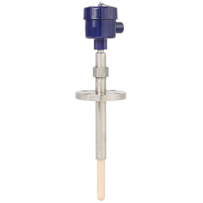
ترمومتر/ثرموكبل بتصميم الياقوت
الوصف
هذا الثرموكبل عالي الحرارة مع أنبوب حماية من الياقوت محكم ضد الغازات تم تطويره خصيصًا للاستخدام في الأجواء الغنية بالهيدروجين.
ومن خلال البنية أحادية البلورة، يحمي الياقوت المعدن النبيل للثرموكبل من الوسائط السامة الضارة في جو العملية العدواني.
تمنع الوصلات المُحكمة الإغلاق الغازات السامة من أن تتمكن من التسرب من المفاعل.
تفرض درجات الحرارة المرتفعة جدًا في العملية متطلبات عالية للغاية على أنابيب الحماية والثرمكوبات.
غالبًا ما تؤدي ظروف العملية هذه إلى حالات إيقاف وتعطيل في التشغيل.
للموافقات الإضافية، راجع الصفحة 8
المزايا
- توفير التكاليف عبر نظام غير غسيلي
- تقليل فترات التوقف غير المخططة
- سلامة معززة ضد تسرب الوسائط السامة من خلال نظام إحكام مزدوج
- تنوع كبير في مواد الجراب الواقي / أنبوب الحماية
- أمان عملي مرتفع مع العمليات حتى 1,700 °C [3,092 °F]
الأسئلة والأجوبة
ما هو أقصى مدى لقياس درجة الحرارة لهذا الثرموكوبل؟
حسب تكوين المستشعر وأنبوب الحماية، تمتد النطاقات المتاحة من -40 °C إلى 1,200 °C وحتى 600 … 1,700 °C و870 … 1,700 °C للنطاقات الأعلى. درجة حرارة العملية القصوى هي 1,700 °C.
هل يناسب هذا الطراز البيئات الخطرة؟
نعم، يحمل الطراز موافقات ATEX وIECEx مع تصنيفات انفجار متعددة مثل Ex ia IIC T* Gb وEx db IIC T6 ... T1 Gb وغيرها، كما يدعم مستوى السلامة الوظيفية SIL 2.
ما هي توصيلات العملية المتاحة؟
تتوفر توصيلات شفة ASME بحجم 1.5" ... 6" وشفة EN 1092-1 بمقاسات DN40 ... DN100، مع تصنيفات ضغط 150...1,500 lb وPN40...PN100.
ما هي مواد أنبوب الحماية؟
تشمل المواد Sapphire وCeramic (بأنواع C530 وC610 وC799) وSilicon carbide (Hexoloy®) بالإضافة إلى الفولاذ المقاوم للصدأ الخارجي، مما يتيح تنوعًا عاليًا حسب ظروف العملية.
ما هو خرج الإشارة والتوصيل الكهربائي؟
إشارة الخرج هي 4-20 mA مع دعم HART، والتوصيل الكهربائي متاح بصيغ M20 x 1.5 أو ½ NPT أو ¾ NPT.
ما مدى ملاءمته للوسائط السامة والأجواء الهيدروجينية؟
أنبوب الحماية من الياقوت أحادي البلورة محكم ضد الغازات ويحمي معدن الثرموكوبل النبيل من الوسائط السامة، ونظام الإغلاق المزدوج يزيد الأمان ضد تسرب الوسائط السامة خارج المفاعل.
ما الذي يميز TC83 عن ثرموكوبلات أخرى؟
يتميز بأنبوب حماية من الياقوت يتحمل العمليات العدوانية حتى 1,700 °C دون الحاجة إلى نظام غسيل (non-purge)، مما يوفر التكاليف ويقلل فترات التوقف غير المخططة.
ما هو معدل الحماية من ingress؟
معدل الحماية IP66، ودرجة الحرارة المحيطة المسموحة للتركيب هي -60 … +80 °C.
| الطراز | TC83 |
| النوع الفرعي | Sapphire-design thermocouple |
| نطاق درجة الحرارة | −40…+1200 °C · −40…+1000 °C · −40…+750 °C · +0…+1600 °C · +600…+1700 °C · +870…+1700 °C · −40…+900 °C · −40…+800 °C · +0…+1260 °C · +0…+1480 °C |
| مستوى السلامة الوظيفية (SIL) | SIL 2 |
| وصلة العملية | ASME 1.5" ... 6"EN 1092-1 DN40 ... DN100ASME 1.5" to 6"EN 1092-1 DN40 to DN100ASME 1.5...6"150...1,500 lbPN40...PN100 |
| درجة حرارة العملية | +0…+1700 °C |
| إشارة الخرج | HART · 4-20mA |
| التغذية | Not specified |
| وصلة كهربائية | M20 x 1.5, ½ NPT, ¾ NPT |
| مادة المجس | Stainless steel 310, 446, Alloy 600, Sapphire, Ceramic, Ceramic C530, Ceramic C610, Ceramic C799, Silicon carbide (Hexoloy®) |
| مادة جراب الحرارة | Ceramic C530, Ceramic C610, Ceramic C799, Silicon carbide (Hexoloy), Ceramic, Stainless steel (outer), Silicon carbide (Hexoloy®) |
| حرارة المحيط | −60…+80 °C |
| تصنيف IP | IP66 |
| الشهادات | CERoHSEACATEXIECExREACH |
| حماية الانفجار | Ex ia IIC T* Gb/-1Ex d IIC T6...T1 Gb X1Ex ia IIC T6...T1 Gb XII 2/-G Ex db IIC T6 ... T1 Gb/-II 2/- G Ex ia IIC T* Gb/-Ex db IIC T6 ... T1 Gb/-Ex db IIC T6...T1 GbEx ia IIC T* GbEx ia IIIC T* DbII 2/-G Ex db IIC Gb/-II 2/-D Ex ia IIC T* Db/-II 2/-G Ex ia IIC Gb/-II 2/-D Ex ia IIC Db/-Ex db IIC Gb/-Ex ia IIC T* Db/-Ex ia IIC Gb/-Ex ia IIC Db/-Ex ia IIC T135°C Db X |
| نوع المستشعر | Type K/J/E/R/S/B |
| فئة المستشعر | Class 1, Class 2, Class 3, Standard, Special |
| طول المجس | 1000 mm |
| قطر المجس | 25 mm |
| جراب الحرارة | نعم |
| شكل جراب الحرارة | fabricated |
| لغات ورقة البيانات | EN, DE |
| Type of measuring element | Thermocouple per IEC 60584-1 or ASTM E230 Types K, J, E, R, S, B |
|---|---|
| Probe tip design (hot junction) | 3 |
| Design with outer and inner protection tube | ■ Insulation rod ■ Welded thermocouple (hot junc - tion) ■ Sapphire inner protection tube ■ Outer protection tube |
| Marking of the polarity | 2 The colour code at the positive poles of the instrument decides the correlation of polarity and terminal. |
| Single thermocouple | ||
|---|---|---|
| Dual thermocouple | ||
| Validity limits of the class accuracy in accordance with IEC 60584-1 | ||
| Type K | Class 2 | -40 ... +1,200 °C [-40 ... +2,192 °F] |
| Class 1 | -40 ... +1,000 °C [-40 ... +1,832 °F] | |
| Type J | Class 2 | -40 ...+750 °C [-40 ... +1,382 °F] |
| Class 1 | -40 ...+750 °C [-40 ... +1,382 °F] | |
| Type E | Class 2 | -40 ...+900 °C [-40 ... +1,652 °F] |
| Class 1 | -40 ...+800 °C [-40 ... +1,472 °F] | |
| Type R | Class 2 | 0 ... 1,600 °C [32 ... 2,912 °F] |
| Class 1 | 0 ... 1,600 °C [32 ... 2,912 °F] | |
| Type S | Class 2 | 0 ... 1,600 °C [32 ... 2,912 °F] |
| Class 1 | 0 ... 1,600 °C [32 ... 2,912 °F] | |
| Type B | Class 3 | 600 ... 1,700 °C [1,112 ... 3,092 °F] |
| Class 1 | 600 ... 1,700 °C [1,112 ... 3,092 °F] | |
| Validity limits of the class accuracy in accordance with ASTM E230 | ||
| Type K | Standard | 0 ... 1,260 °C [32 ... 2,300 °F] |
| Special | 0 ... 1,260 °C [32 ... 2,300 °F] | |
| Type J | Standard | 0 ... 760 °C [32 ... 1,400 °F] |
| Special | 0 ... 760 °C [32 ... 1,400 °F] | |
| Type E | Standard | 0 ... 870 °C [32 ... 1,598 °F] |
| Special | 0 ... 870 °C [32 ... 1,598 °F] | |
| Type R | Standard | 0 ... 1,480 °C [32 ... 2,696 °F] |
| Special | 0 ... 1,480 °C [32 ... 2,696 °F] | |
| Type S | Standard | 0 ... 1,480 °C [32 ... 2,696 °F] |
| Special | 0 ... 1,480 °C [32 ... 2,696 °F] | |
| Type B | Standard | - |
| Special | 870 ... 1,700 °C [1,598 ... 3,092 °F] |
| Model | Material | Cable inlet thread size | Ingress protection (max.) 1) 2) IEC/EN 60529 | Cap | Surface | Connection to neck tube | |
|---|---|---|---|---|---|---|---|
| 1/4000 | 1/4000 F | Aluminium | ■ ½NPT ■ ¾NPT ■ M20 x 1.5 | IP66 | Screw-on lid | Blue, painted (RAL 5022) | ½NPT |
| 5/6000 1/4000 S | 7/8000 Stainless steel | 7/8000 DIH50 andere ■ ½NPT ■ ¾NPT ■ M20 x 1.5 | KN4-P Anschlussgehäuse IP66 | BVC Screw-on lid | Natural finish | ½NPT | |
| 5/6000 | 5/6000 | Aluminium | ■ 3x½NPT ■ 3x¾NPT ■ 3 x M20 x 1.5 | IP66 | Screw-on lid | Blue, painted (RAL 5022) | ½NPT |
| 7/8000 5/6000 | 7/8000 DIH50 Stainless steel | andere Anschlussgehäuse ■ 3x½NPT ■ 3x¾NPT ■ 3 x M20 x 1.5 | KN4-P BVC IP66 | Screw-on lid | Natural finish | ½NPT | |
| 7/8000 | 7/8000W | Aluminium | ■ ½NPT ■ ¾NPT ■ M20 x 1.5 | IP66 | Screw-on lid | Blue, painted (RAL 5022) | ½NPT |
| 7/8000 DIH50 7/8000 S | andere Anschlussgehäuse Stainless steel | KN4-P BVC ■ ½NPT ■ ¾NPT ■ M20 x 1.5 | IP66 | Screw-on lid | Natural finish | ½NPT | |
| PIH-L | Aluminium | ■ ½NPT/ closed ■ M20 x 1.5 / closed ■ 2x½NPT ■ 2 x M20 x 1.5 | IP66 | Screw-on lid, flat | Blue lid, painted Grey lower body, painted | ■ ½NPT ■ M20 x 1.5 | |
| PIH-H | Aluminium | ■ ½NPT/ closed ■ M20 x 1.5 / closed ■ 2x½NPT ■ 2 x M20 x 1.5 | IP66 | Screw-on lid, high | Blue lid, painted | ■ ½NPT ■ M20 x 1.5 | |
| Grey lower body, painted |
| Cable inlet | Colour Ingress pro- tection | (max.) IEC/EN 60529 1) | Cable inlet thread size | Min./Max. ambi- ent temperature |
|---|---|---|---|---|
| Standard cable inlet | Natural finish | IP65 | ■ M20 x 1.5 ■ ½NPT | -40 ...+80 °C [-40 ...+176 °F] |
| Plastic cable gland (cable Ø6...10 mm) | ■ Black ■ Grey | IP66 | ■ M20 x 1.5 ■ ½NPT | -40 ...+80 °C [-40 ...+176 °F] |
| Plastic cable gland (cable Ø6... 10 mm), Ex e | ■ Light blue ■ Black | IP66 | ■ M20 x 1.5 ■ ½NPT | ■ -20 ...+80 °C [-4 ...+176 °F] ■ -40 ...+70 °C [-40 ...+158 °F] |
| Nickel-plated brass cable gland (cable Ø6... 12 mm) | Natural finish | IP66 | ■ M20 x 1.5 ■ ½NPT | -60 2) / -40 ...+80 °C [-76 / -40 ...+176 °F] |
| Nickel-plated brass cable gland (cable Ø6... 12 mm), Ex e | Natural finish | IP66 | ■ M20 x 1.5 ■ ½NPT | -60 2) / -40 ...+80 °C [-76 / -40 ...+176 °F] |
| Stainless steel cable gland (cable Ø7... 12 mm) | Natural finish | IP66 | ■ M20 x 1.5 ■ ½NPT | -60 2) / -40 ...+80 °C [-76 / -40 ...+176 °F] |
| Stainless steel cable gland (cable Ø7... 12 mm), Ex e | Natural finish | IP66 | ■ M20 x 1.5 ■ ½NPT | -60 2) / -40 ...+80 °C [-76 / -40 ...+176 °F] |
| Plain threaded | - | IP00 | ■ M20 x 1.5 ■ ½NPT | - |
| Sealing plugs for shipping | Transparent | - | ■ M20 x 1.5 ■ ½NPT | -40 ...+80 °C [-40 ...+176 °F] |
عرض الكل (13)
| Cable inlet | Explosion protection | |||||
|---|---|---|---|---|---|---|
| With- out | Ex i (gas) Zone 0, 1, 2 | Ex i (dust) Zone 20, 21, 22 | Ex e (gas) Zone 1, 2 | Ex t (dust) Zone 21, 22 | Ex nA (gas) Zone 2 | |
| Standard | x | x | - | - | - | - |
| Plastic cable gland | x | x | - | - | - | - |
| Plastic cable gland (light blue), Ex e | x | x | x | - | - | - |
| Plastic cable gland (black), Ex e | x | x | x | x | x | x |
| Brass cable gland, nickel-plated | x | x | x | - | - | - |
| Brass cable gland, nickel-plated, Ex e | x | x | x | x | x | x |
| Stainless steel cable gland | x | x | x | - | - | - |
| Stainless steel cable gland, Ex e | x | x | x | x | x | x |
| Plain threaded | x | x | x 1) | x 1) | x 1) | x 1) |
| Sealing plugs for shipping | Not applicable, transport protection 1) |
| Transmitter models | Model T16 | Model T38 |
|---|---|---|
| Transmitter data sheet | TE 16.01 | TE 38.01 |
| Figure | ||
| Output | ||
| 4 ...20mA | x | x |
| HART ® protocol | - | x |
| Cable inlet | ■ Type K ■ Type J ■ Type E ■ Type R ■ Type S ■ Type B | ■ Type K ■ Type J ■ Type E ■ Type R ■ Type S ■ Type B |
| Explosion protection | Ex version possible |
| Possible connection heads for transmitter mounting | Model T16 | Model T38 |
|---|---|---|
| 1/4000 | ○ | ○ |
| 5/6000 | ○ | ○ |
| 7/8000 | ○ | ○ |
| TIF50 | - | ○ |
| PIH-L/PIH-H | ○ | ○ |
| Operating temperature | |
|---|---|
| Ceramic protection tube | Max. 1,700 °C [3,082 °F] |
| → Others on request | |
| Ambient and storage temperature range | -60 1) / -40 ...+80 °C [-76 1) / -40 ...+176 °F] |
| Logo | Description | Region |
|---|---|---|
| EU declaration of conformity | European Union |
| Logo | Description | Region | |
|---|---|---|---|
| EU declaration of conformity | European Union | ||
| ATEX directive Hazardous areas | |||
| - Ex d | 1 gas II 2/-G Ex db IIC T6 ...T1 Gb/- 1 gas II 2/-G Ex db IIC Gb/- | ||
| - Ex i | 1 gas II 2/- GEx ia IIC T* Gb/- 21 dust II 2/- D Ex ia IIIC T* Db/- II 2/- GEx ia IIC Gb/- | ||
| Zone | 1 gas | ||
| 21 dust II 2/- D Ex ia IIIC Db/- | |||
| IECEx Hazardous areas | International | ||
| - Ex d | 1 gas Ex db IIC T6 ...T1 Gb/- 1 gas Ex db IIC Gb/- | ||
| - Ex i | 1 gas Ex ia IIC T* Gb/- 21 dust Ex ia IIIC T* Db/- 1 gas Ex ia IIC Gb/- 21 dust Ex ia IIIC Db/- | ||
| EAC | Eurasian Economic Com- munity | ||
| Hazardous areas | |||
| PAC Kazakhstan Metrology, measurement technology | Kazakhstan | ||
| - | PAC Ukraine Metrology, measurement technology | Ukraine | |
| PAC Uzbekistan Metrology, measurement technology | Uzbekistan |
| Certificates | ■ 2.2 test report per EN 10204 (e.g. state-of-the-art manufacturing, material proof, indica - tion accuracy) ■ 3.1 inspection certificate per EN 10204 (e.g. material proof for wetted metal parts, indi - cation accuracy, calibration certificate) ■ Calibration at 3 test points (900 °C [1,652 °F], 1,000 °C [1,832 °F] and 1,100 °C [2,012 °F]) ■ Calibration at 3 test points (1,000 °C [1,832 °F], 1,200 °C [2,192 °F] and 1,300 °C [2,372 °F]) |
|---|
| Logo | Description |
|---|---|
| SIL IEC 61508 / IEC 61511 | SIL 2 Functional safety |
| Legend: | |
|---|---|
| A | 14739408.01 Nominal length |
| U | Insertion length |
| N | E Neck tube / Support tube length |
| X | Neck tube / Support tube length below process connection |
| ØF | Diameter of outer protection tube |
لم تجد الإجابة في الوثائق؟ سيرد المهندس خلال يوم عمل.
اسأل المهندس →