
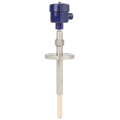
צמד תרמי בעיצוב ספיר
תיאור
צמד תרמי לטמפרטורות גבוהות זה עם שרוול הגנה מספיר אטום לגז פותח במיוחד לשימוש באטמוספרה מימנית.
בזכות המבנה החד-גבישי, הספיר מגן על המתכת האצילה של הצמד התרמי מפני מדיה רעילה מזיקה בתנאי התהליך האגרסיביים.
צמדים אטומים הרמטית מונעים מגזים רעילים ליכולת להשתחרר מהכור.
הטמפרטורות הגבוהות בתהליך מציבות דרישות גבוהות מאוד לשרוולי ההגנה ולצמדים התרמיים.
תנאי תהליך אלה מובילים לעיתים קרובות להשבתות ולהפסקות בפעולה.
לאישורים נוספים, ראה עמוד 8
תכונות מיוחדות
- חיסכון בעלויות הודות למערכת ללא שטיפה
- הפחתת השבתות בלתי מתוכננות
- בטיחות מוגברת מפני דליפת חומרים רעילים באמצעות מערכת איטום כפולה
- מגוון רחב של חומרים לתרמו-באר / צינור הגנה
- בטיחות תהליך גבוהה בתהליכים עד 1,700 °C [3,092 °F]
שאלות ותשובות
מהו טווח הטמפרטורות של התהליך?
הטווח המרבי הוא 0 … 1,700 °C; טווחים ספציפיים תלויים בסוג החיישן ובחומר השרוול (לדוגמה: -40 … +750 °C, -40 … +1,200 °C, 600 … 1,700 °C).
אילו סוגי צמדים תרמיים נתמכים?
Type K/J/E/R/S/B, במחלקות Class 1, Class 2, Class 3, Standard ו-Special.
מהם אפשרויות החיבור לתהליך?
ASME 1.5" … 6" ו-EN 1092-1 DN40 … DN100, עם דירוגי לחץ 150…1,500 lb ו-PN40…PN100.
האם המכשיר מתאים לאזורים מסוכנים?
כן — קיימים אישורי ATEX ו-IECEx, לדוגמה Ex ia IIC T* Gb ו-Ex db IIC T6 ... T1 Gb, וכן רמת שלמות בטיחות SIL 2.
מה מבדיל את ה-TC83 מצמדים תרמיים רגילים?
שרוול ההגנה מספיר בעל המבנה החד-גבישי, האטום לגז, המגן על המתכת האצילה מפני מדיה רעילה ומתאים לאטמוספרות מימניות עד 1,700 °C.
מהו אות הפלט והחיבור החשמלי?
אות פלט HART / 4-20 mA; חיבור חשמלי M20 x 1.5, ½ NPT או ¾ NPT.
מהו דירוג ההגנה מפני חדירה?
IP66, עם טווח טמפרטורת סביבה של -60 … +80 °C. ---
| דגם | TC83 |
| תת-קטגוריה | Sapphire-design thermocouple |
| טווח טמפרטורה | −40…+1200 °C · −40…+1000 °C · −40…+750 °C · +0…+1600 °C · +600…+1700 °C · +870…+1700 °C · −40…+900 °C · −40…+800 °C · +0…+1260 °C · +0…+1480 °C |
| רמת בטיחות תפקודית (SIL) | SIL 2 |
| חיבור תהליך | ASME 1.5" ... 6"EN 1092-1 DN40 ... DN100ASME 1.5" to 6"EN 1092-1 DN40 to DN100ASME 1.5...6"150...1,500 lbPN40...PN100 |
| טמפ׳ תהליך | +0…+1700 °C |
| אות יציאה | HART · 4-20mA |
| הזנה | Not specified |
| חיבור חשמלי | M20 x 1.5, ½ NPT, ¾ NPT |
| חומר גשש | Stainless steel 310, 446, Alloy 600, Sapphire, Ceramic, Ceramic C530, Ceramic C610, Ceramic C799, Silicon carbide (Hexoloy®) |
| חומר תרמופור | Ceramic C530, Ceramic C610, Ceramic C799, Silicon carbide (Hexoloy), Ceramic, Stainless steel (outer), Silicon carbide (Hexoloy®) |
| טמפ׳ סביבה | −60…+80 °C |
| דרגת הגנה IP | IP66 |
| תקנים | CERoHSEACATEXIECExREACH |
| הגנת התפוצצות | Ex ia IIC T* Gb/-1Ex d IIC T6...T1 Gb X1Ex ia IIC T6...T1 Gb XII 2/-G Ex db IIC T6 ... T1 Gb/-II 2/- G Ex ia IIC T* Gb/-Ex db IIC T6 ... T1 Gb/-Ex db IIC T6...T1 GbEx ia IIC T* GbEx ia IIIC T* DbII 2/-G Ex db IIC Gb/-II 2/-D Ex ia IIC T* Db/-II 2/-G Ex ia IIC Gb/-II 2/-D Ex ia IIC Db/-Ex db IIC Gb/-Ex ia IIC T* Db/-Ex ia IIC Gb/-Ex ia IIC Db/-Ex ia IIC T135°C Db X |
| סוג חיישן | Type K/J/E/R/S/B |
| מחלקת חיישן | Class 1, Class 2, Class 3, Standard, Special |
| אורך גשש | 1000 mm |
| קוטר גשש | 25 mm |
| תרמופור | כן |
| צורת תרמופור | fabricated |
| שפות גיליון נתונים | EN, DE |
| Type of measuring element | Thermocouple per IEC 60584-1 or ASTM E230 Types K, J, E, R, S, B |
|---|---|
| Probe tip design (hot junction) | 3 |
| Design with outer and inner protection tube | ■ Insulation rod ■ Welded thermocouple (hot junc - tion) ■ Sapphire inner protection tube ■ Outer protection tube |
| Marking of the polarity | 2 The colour code at the positive poles of the instrument decides the correlation of polarity and terminal. |
| Single thermocouple | ||
|---|---|---|
| Dual thermocouple | ||
| Validity limits of the class accuracy in accordance with IEC 60584-1 | ||
| Type K | Class 2 | -40 ... +1,200 °C [-40 ... +2,192 °F] |
| Class 1 | -40 ... +1,000 °C [-40 ... +1,832 °F] | |
| Type J | Class 2 | -40 ...+750 °C [-40 ... +1,382 °F] |
| Class 1 | -40 ...+750 °C [-40 ... +1,382 °F] | |
| Type E | Class 2 | -40 ...+900 °C [-40 ... +1,652 °F] |
| Class 1 | -40 ...+800 °C [-40 ... +1,472 °F] | |
| Type R | Class 2 | 0 ... 1,600 °C [32 ... 2,912 °F] |
| Class 1 | 0 ... 1,600 °C [32 ... 2,912 °F] | |
| Type S | Class 2 | 0 ... 1,600 °C [32 ... 2,912 °F] |
| Class 1 | 0 ... 1,600 °C [32 ... 2,912 °F] | |
| Type B | Class 3 | 600 ... 1,700 °C [1,112 ... 3,092 °F] |
| Class 1 | 600 ... 1,700 °C [1,112 ... 3,092 °F] | |
| Validity limits of the class accuracy in accordance with ASTM E230 | ||
| Type K | Standard | 0 ... 1,260 °C [32 ... 2,300 °F] |
| Special | 0 ... 1,260 °C [32 ... 2,300 °F] | |
| Type J | Standard | 0 ... 760 °C [32 ... 1,400 °F] |
| Special | 0 ... 760 °C [32 ... 1,400 °F] | |
| Type E | Standard | 0 ... 870 °C [32 ... 1,598 °F] |
| Special | 0 ... 870 °C [32 ... 1,598 °F] | |
| Type R | Standard | 0 ... 1,480 °C [32 ... 2,696 °F] |
| Special | 0 ... 1,480 °C [32 ... 2,696 °F] | |
| Type S | Standard | 0 ... 1,480 °C [32 ... 2,696 °F] |
| Special | 0 ... 1,480 °C [32 ... 2,696 °F] | |
| Type B | Standard | - |
| Special | 870 ... 1,700 °C [1,598 ... 3,092 °F] |
| Model | Material | Cable inlet thread size | Ingress protection (max.) 1) 2) IEC/EN 60529 | Cap | Surface | Connection to neck tube | |
|---|---|---|---|---|---|---|---|
| 1/4000 | 1/4000 F | Aluminium | ■ ½NPT ■ ¾NPT ■ M20 x 1.5 | IP66 | Screw-on lid | Blue, painted (RAL 5022) | ½NPT |
| 5/6000 1/4000 S | 7/8000 Stainless steel | 7/8000 DIH50 andere ■ ½NPT ■ ¾NPT ■ M20 x 1.5 | KN4-P Anschlussgehäuse IP66 | BVC Screw-on lid | Natural finish | ½NPT | |
| 5/6000 | 5/6000 | Aluminium | ■ 3x½NPT ■ 3x¾NPT ■ 3 x M20 x 1.5 | IP66 | Screw-on lid | Blue, painted (RAL 5022) | ½NPT |
| 7/8000 5/6000 | 7/8000 DIH50 Stainless steel | andere Anschlussgehäuse ■ 3x½NPT ■ 3x¾NPT ■ 3 x M20 x 1.5 | KN4-P BVC IP66 | Screw-on lid | Natural finish | ½NPT | |
| 7/8000 | 7/8000W | Aluminium | ■ ½NPT ■ ¾NPT ■ M20 x 1.5 | IP66 | Screw-on lid | Blue, painted (RAL 5022) | ½NPT |
| 7/8000 DIH50 7/8000 S | andere Anschlussgehäuse Stainless steel | KN4-P BVC ■ ½NPT ■ ¾NPT ■ M20 x 1.5 | IP66 | Screw-on lid | Natural finish | ½NPT | |
| PIH-L | Aluminium | ■ ½NPT/ closed ■ M20 x 1.5 / closed ■ 2x½NPT ■ 2 x M20 x 1.5 | IP66 | Screw-on lid, flat | Blue lid, painted Grey lower body, painted | ■ ½NPT ■ M20 x 1.5 | |
| PIH-H | Aluminium | ■ ½NPT/ closed ■ M20 x 1.5 / closed ■ 2x½NPT ■ 2 x M20 x 1.5 | IP66 | Screw-on lid, high | Blue lid, painted | ■ ½NPT ■ M20 x 1.5 | |
| Grey lower body, painted |
| Cable inlet | Colour Ingress pro- tection | (max.) IEC/EN 60529 1) | Cable inlet thread size | Min./Max. ambi- ent temperature |
|---|---|---|---|---|
| Standard cable inlet | Natural finish | IP65 | ■ M20 x 1.5 ■ ½NPT | -40 ...+80 °C [-40 ...+176 °F] |
| Plastic cable gland (cable Ø6...10 mm) | ■ Black ■ Grey | IP66 | ■ M20 x 1.5 ■ ½NPT | -40 ...+80 °C [-40 ...+176 °F] |
| Plastic cable gland (cable Ø6... 10 mm), Ex e | ■ Light blue ■ Black | IP66 | ■ M20 x 1.5 ■ ½NPT | ■ -20 ...+80 °C [-4 ...+176 °F] ■ -40 ...+70 °C [-40 ...+158 °F] |
| Nickel-plated brass cable gland (cable Ø6... 12 mm) | Natural finish | IP66 | ■ M20 x 1.5 ■ ½NPT | -60 2) / -40 ...+80 °C [-76 / -40 ...+176 °F] |
| Nickel-plated brass cable gland (cable Ø6... 12 mm), Ex e | Natural finish | IP66 | ■ M20 x 1.5 ■ ½NPT | -60 2) / -40 ...+80 °C [-76 / -40 ...+176 °F] |
| Stainless steel cable gland (cable Ø7... 12 mm) | Natural finish | IP66 | ■ M20 x 1.5 ■ ½NPT | -60 2) / -40 ...+80 °C [-76 / -40 ...+176 °F] |
| Stainless steel cable gland (cable Ø7... 12 mm), Ex e | Natural finish | IP66 | ■ M20 x 1.5 ■ ½NPT | -60 2) / -40 ...+80 °C [-76 / -40 ...+176 °F] |
| Plain threaded | - | IP00 | ■ M20 x 1.5 ■ ½NPT | - |
| Sealing plugs for shipping | Transparent | - | ■ M20 x 1.5 ■ ½NPT | -40 ...+80 °C [-40 ...+176 °F] |
הצגת הכול (13)
| Cable inlet | Explosion protection | |||||
|---|---|---|---|---|---|---|
| With- out | Ex i (gas) Zone 0, 1, 2 | Ex i (dust) Zone 20, 21, 22 | Ex e (gas) Zone 1, 2 | Ex t (dust) Zone 21, 22 | Ex nA (gas) Zone 2 | |
| Standard | x | x | - | - | - | - |
| Plastic cable gland | x | x | - | - | - | - |
| Plastic cable gland (light blue), Ex e | x | x | x | - | - | - |
| Plastic cable gland (black), Ex e | x | x | x | x | x | x |
| Brass cable gland, nickel-plated | x | x | x | - | - | - |
| Brass cable gland, nickel-plated, Ex e | x | x | x | x | x | x |
| Stainless steel cable gland | x | x | x | - | - | - |
| Stainless steel cable gland, Ex e | x | x | x | x | x | x |
| Plain threaded | x | x | x 1) | x 1) | x 1) | x 1) |
| Sealing plugs for shipping | Not applicable, transport protection 1) |
| Transmitter models | Model T16 | Model T38 |
|---|---|---|
| Transmitter data sheet | TE 16.01 | TE 38.01 |
| Figure | ||
| Output | ||
| 4 ...20mA | x | x |
| HART ® protocol | - | x |
| Cable inlet | ■ Type K ■ Type J ■ Type E ■ Type R ■ Type S ■ Type B | ■ Type K ■ Type J ■ Type E ■ Type R ■ Type S ■ Type B |
| Explosion protection | Ex version possible |
| Possible connection heads for transmitter mounting | Model T16 | Model T38 |
|---|---|---|
| 1/4000 | ○ | ○ |
| 5/6000 | ○ | ○ |
| 7/8000 | ○ | ○ |
| TIF50 | - | ○ |
| PIH-L/PIH-H | ○ | ○ |
| Operating temperature | |
|---|---|
| Ceramic protection tube | Max. 1,700 °C [3,082 °F] |
| → Others on request | |
| Ambient and storage temperature range | -60 1) / -40 ...+80 °C [-76 1) / -40 ...+176 °F] |
| Logo | Description | Region |
|---|---|---|
| EU declaration of conformity | European Union |
| Logo | Description | Region | |
|---|---|---|---|
| EU declaration of conformity | European Union | ||
| ATEX directive Hazardous areas | |||
| - Ex d | 1 gas II 2/-G Ex db IIC T6 ...T1 Gb/- 1 gas II 2/-G Ex db IIC Gb/- | ||
| - Ex i | 1 gas II 2/- GEx ia IIC T* Gb/- 21 dust II 2/- D Ex ia IIIC T* Db/- II 2/- GEx ia IIC Gb/- | ||
| Zone | 1 gas | ||
| 21 dust II 2/- D Ex ia IIIC Db/- | |||
| IECEx Hazardous areas | International | ||
| - Ex d | 1 gas Ex db IIC T6 ...T1 Gb/- 1 gas Ex db IIC Gb/- | ||
| - Ex i | 1 gas Ex ia IIC T* Gb/- 21 dust Ex ia IIIC T* Db/- 1 gas Ex ia IIC Gb/- 21 dust Ex ia IIIC Db/- | ||
| EAC | Eurasian Economic Com- munity | ||
| Hazardous areas | |||
| PAC Kazakhstan Metrology, measurement technology | Kazakhstan | ||
| - | PAC Ukraine Metrology, measurement technology | Ukraine | |
| PAC Uzbekistan Metrology, measurement technology | Uzbekistan |
| Certificates | ■ 2.2 test report per EN 10204 (e.g. state-of-the-art manufacturing, material proof, indica - tion accuracy) ■ 3.1 inspection certificate per EN 10204 (e.g. material proof for wetted metal parts, indi - cation accuracy, calibration certificate) ■ Calibration at 3 test points (900 °C [1,652 °F], 1,000 °C [1,832 °F] and 1,100 °C [2,012 °F]) ■ Calibration at 3 test points (1,000 °C [1,832 °F], 1,200 °C [2,192 °F] and 1,300 °C [2,372 °F]) |
|---|
| Logo | Description |
|---|---|
| SIL IEC 61508 / IEC 61511 | SIL 2 Functional safety |
| Legend: | |
|---|---|
| A | 14739408.01 Nominal length |
| U | Insertion length |
| N | E Neck tube / Support tube length |
| X | Neck tube / Support tube length below process connection |
| ØF | Diameter of outer protection tube |
לא מצאתם תשובה בתיעוד? מהנדס יענה במהלך יום עסקים.
שאלו מהנדס →