
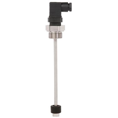
Float switch
Description
The RLS-1000 is a robust, reliable and inexpensive float switch. Since the monitoring of levels as well as dry-run protection and overflow protection are cost-sensitive applications in the machine-building industry, a float switch is the ideal solution for many plants. The RLS-1000 reliably detects the level in vessels with water, oil, diesel or other liquids by means of a permanent magnet and frictionless reed contacts at max. 4 defined switch points and can be used in a medium temperature range from -30 to +150 °C [-22 to +302 °F].
The compact float switch is simple, convenient and fast to integrate, because it does not need to be calibrated or set during the installation. This greatly improves the ease of handling, especially in confined installation situations. Also, since its robust design makes it resistant to vibrations and shocks, maintenance costs are minimal
.
Fig. left: Angular connector, float from NBR Fig. right: Circular connector M12 x 1, float from stainless steel
Special features
- Maximum reliability thanks to high-quality reed contacts
- Very high variety and customer-specific solutions possible
- Simple and fast installation
| Model | RLS-1000 |
| Product family | RLS |
| Subcategory | Float switch |
| Level ranges | 0.06…1.5 m |
| Process connection | G 1/2, installation from outsideG 3/4, installation from outsideG 1, installation from outsideG 1 ½, installation from outsideG 2, installation from outsideFlange DN 50, form B per EN 1092-1 (DIN 2527), PN 16, installation from outsideG ⅛, installation from insideG ¼, installation from insideG ⅜, installation from insideG ½, installation from insideG 1/2G 3/4G 1G 1 ½G 2G ⅛ BG ¼ BG ⅜ BG ½ BFlange |
| Process temperature | −30…+150 °C |
| Max process pressure | 40 bar |
| Measurement technology | float |
| Output signal | SP1 · SP2 · SP3 · SP4 |
| Electrical connection | Angular connector DIN EN 175301-803 A, Circular connector M12 x 1 (4-pin), Cable outlet, Connection housing 'standard', Connection housing 'compact' |
| Wetted parts material | Stainless steel 316Ti, Buna / NBR, PP, PA6.6 |
| Ambient temperature | −30…+80 °C |
| IP rating | IP65 |
| Certifications | RoHSCEChina RoHS |
| Datasheet languages | EN |
| Measuring principle | Potential-free switching reed contacts are triggered by a magnet in the float. | ||
|---|---|---|---|
| Guide tube length L | 60 ... 1,500 mm[2.5 ... 59 in], other lengths on request | ||
| Output signal | Up to 4 switch points, depending on the electrical connection: SP1, SP2, SP3, SP4 | ||
| Switching function | Alternatively normally open (NO), normally closed (NC) or change-over (SPDT) contact - on rising level | ||
| Switch position | Specified in mm, starting from the upper sealing face (SP1 ... SP4) At the end of the guide tube ≈ 45 mm[≈ 1.8 in] cannot be used for switch positions. | ||
| Distance between switch points 1) | Minimum distance SP1 to the upper sealing face: 50 mm[2.0 in] Minimum distance between the switch points: 50 mm[2.0 in], for floats with outer ∅=44mm[1.7 in], 52 mm[2.0 in] 30 mm[1.2 in], for floats with outer ∅=18mm[0.7 in], 22 mm[0.9 in], 25 mm[1.0 in], 30 mm[1.2 in] Minimum distance with 3 switch points: 80 mm[3.1 in], either between SP1 and SP2 or SP2 and SP3 Minimum distance with 4 switch points: 80 mm[3.1 in], between SP2 and SP3 | ||
| Switching power 2) | Floats with outer Normally open, normally closed: Change-over contact: | diameter ∅D=44mm[1.7 in], 52 mm[2.0 in] AC 230 V; 100 VA; 1 A; 50 ... 60 Hz DC 230 V; 50 W;0.5 A AC 230 V; 40 VA; 1 A; 50 ... 60 Hz DC 230 V; 20 W;0.5 A | |
| Floats with outer diameter ∅D=18mm[0.7 in], 22 mm[0.9 in], 25 mm[1.0 in], 30 mm[1.2 in] | |||
| Normally open, normally closed: | AC 100 V; 10 VA; 0.5 A; 50 ... 60 Hz DC 100 V; 10 W;0.5 A | ||
| Change-over contact: | |||
| 100 V; 5 VA; 0.25 A; 50 ... 60 Hz | |||
| DC | AC | 100 V; 5 W;0.25 A | |
| Accuracy | ±3 mmswitch point accuracy incl. hysteresis, non-repeatability | ||
| Mounting position | Vertical ±30° | ||
| Process connection | ■ G1/2, installation from outside 3) ■ G3/4, installation from outside 4) ■ G1, installation from outside ■ G1½, installation from outside | ■ G⅛, installation from inside 5) 6) ■ G¼, installation from inside 5) 6) ■ G⅜, installation from inside 5) ■ G½, installation from inside 5) | |
| steel | on page 3 | ||
| Case | Stainless steel 316Ti | ||
| Non-wetted | |||
| Material | ■ Flange DN | ||
| ■ G2, installation from outside | |||
| 50, form B per EN 1092-1 | |||
| (DIN 2527), PN 16, installation from outside | |||
| Process connection, guide tube Stainless Float See | |||
| table | |||
| table | |||
| Wetted | Electrical | ||
| connection | |||
| 3 | |||
| temperatures | |||
| °F] | |||
| -30 …+80 °C [-22 | |||
| Medium | |||
| -30 …+120 | |||
| Permissible | |||
| …+176 7) 9) | |||
| °C [-22 | |||
| …+248 | °F] | ||
| on page | |||
| 8) 9) | |||
| …+302 °F] | |||
| °C | |||
| [-22 | |||
| -30 …+150 | |||
| See |
| Electrical connections 1) | Max. switch point definition | Ingress protection per IEC/EN 60529 2) | Protection class | Material | Cable length |
|---|---|---|---|---|---|
| Angular connector DIN EN 175301-803 A 3) 4) | ■ 2 NO/NC ■ 1 SPDT | IP65 | II | PA | - |
| Circular connector M12 x 1 (4-pin) 4) | ■ 3 NO/NC ■ 1 NO/NC + 1 SPDT | IP65 | II | TPU, brass | |
| Cable outlet 4) | ■ 4 NO/NC ■ 4 SPDT | IP67 | II | PVC | ■ 2 m[6.5 ft] ■ 5 m[16.4 ft] ■ other |
| Cable outlet 4) | ■ 4 NO/NC ■ 4 SPDT | IP67 | II | PUR | lengths on request |
| Cable outlet 4) | ■ 4 NO/NC ■ 2 NO/NC + 1 SPDT | IP67 | II | Silicone | |
| Cable outlet 'shipbuilding' | ■ 4 NO/NC ■ 4 SPDT | IP67 | II | Polyolefin | |
| Connection housing 'standard' Dimensions: 75 x 80x57mm [3.0 x 3.1 x 2.2 in] For cable diameter: 5 ...10mm [0.2 ... 0.4 in] | ■ 4 NO/NC ■ 4 SPDT | IP66 | I | Case from aluminium, cable gland from polyamide | - |
| Connection housing 'compact' Dimensions: 58 x 64x36mm [2.3 x 2.5 x 1.4 in] For cable diameter: 5 ...10mm [0.2 ... 0.4 in] | ■ 4 NO/NC ■ 2 NO/NC + 1 SPDT ■ 2 SPDT | IP66 | II |
| Float | Form | Outer diameter∅D | Height H | Operating pressure | Medium temperature | Density | Material |
|---|---|---|---|---|---|---|---|
| Cylinder 4) 7) | 44 mm[1.7 in] | 52 mm[2.0 in] | ≤ 16 bar [≤ 232 psi] | -30 ...+150 °C [-22 ...+302 °F] | ≥ 750 kg/m³ [46.8 lbs/ft³] | 316Ti | |
| H | Cylinder 5) | 30 mm[1.2 in] | 36 mm[1.4 in] | ≤ 10 bar [≤ 145 psi] | -30 ...+120 °C [-22 ...+248 °F] | ≥ 850 kg/m³ [53.1 lbs/ft³] | 316Ti |
| ∅D | Cylinder 5) 3) | 25 mm[1.0 in] | 17 mm[0.7 in] | ≤ 16 bar [≤ 232 psi] | -30 ...+80 °C [-22 ...+176 °F] | ≥ 750 kg/m³ [46.8 lbs/ft³] | Buna / NBR |
| Cylinder 4) 6) 9) | 25 mm[1.0 in] | 23 mm[0.9 in] | ≤ 4 bar [≤ 58.0 psi] | -25 ...+80 °C [-13 ...+176 °F] | ≥ 700 kg/m³ [43.7 lbs/ft³] | PP | |
| Cylinder 4) 6) 9) | 25 mm[1.0 in] | 23 mm[0.9 in] | ≤ 4 bar [≤ 58.0 psi] | -25 ...+80 °C [-13 ...+176 °F] | ≥ 750 kg/m³ [46.8 lbs/ft³] | PA6.6 | |
| Cylinder 5) 9) | 22 mm[0.9 in] | 29 mm[1.1 in] | ≤ 16 bar [≤ 232 psi] | -30 ...+120 °C [-22 ...+248 °F] | ≥ 850 kg/m³ [53.1 lbs/ft³] | 316Ti | |
| Cylinder 4) 6) 9) | 18 mm[0.7 in] | 32 mm[1.3 in] | ≤ 16 bar [≤ 232 psi] | -30 ...+80 °C [-22 ...+176 °F] | ≥ 750 kg/m³ [46.8 lbs/ft³] | Buna / NBR | |
| ∅D H | Sphere 6) 7) | 52 mm[2.0 in] | 52 mm[2.0 in] | ≤ 40 bar [≤ 580 psi] | -30 ...+150 °C [-22 ...+302 °F] | ≥ 750 kg/m³ [46.8 lbs/ft³] | 316Ti |
| Normally open/normally closed (NO/NC) | Change-over contact (SPDT) | |
|---|---|---|
| 2 switch points SP1 1 2 SP2 1 3 | 1 switch point SP1 1 2 3 |
View all (11)
| Process connection | Dead band inmm | ||||||
|---|---|---|---|---|---|---|---|
| Outer diameter float ∅D | ∅18mm [0.7 in] | ∅22mm [0.9 in] | ∅25mm [1.0 in] | ∅25mm [1.0 in] | ∅30mm [1.2 in] | ∅44mm [1.7 in] | ∅52mm [2.0 in] |
| Float height H | H 32mm [1.3 in] | H 29mm [1.1 in] | H 17mm [0.7 in] | H 23mm [0.9 in] | H 36mm [1.4 in] | H 52mm [2.0 in] | H 52mm [2.0 in] |
| G 1/2 (from outside) | 35 mm[1.4 in] | - | - | - | - | - | - |
| G 3/4 (from outside) | 35 mm[1.4 in] | 35 mm[1.4 in] | - | - | - | - | - |
| G 1 (from outside) | 35 mm[1.4 in] | 35 mm[1.4 in] | 25 mm[1.0 in] | 35 mm[1.4 in] | 35 mm[1.4 in] | - | - |
| G 1 ½(from outside) | - | - | 25 mm[1.0 in] | - | 35 mm[1.4 in] | 45 mm[1.8 in] | - |
| G 2 (from outside) | - | - | 25 mm[1.0 in] | - | 40 mm[1.6 in] | 50 mm[2.0 in] | 50 mm[2.0 in] |
| Flange (from outside) | - | - | 5 mm[0.2 in] | - | 20 mm[0.8 in] | 30 mm[1.2 in] | 30 mm[1.2 in] |
| G ⅛ B (from inside) | 15 mm[0.6 in] | 20 mm[0.8 in] | 15 mm[0.6 in] | 20 mm[0.8 in] | 30 mm[1.2 in] | - | - |
| G ¼ B (from inside) | 20 mm[0.8 in] | 25 mm[1.0 in] | 20 mm[0.8 in] | 25 mm[1.0 in] | 35 mm[1.4 in] | 40 mm[1.6 in] | 40 mm[1.6 in] |
| G ⅜B(from inside) | 20 mm[0.8 in] | 25 mm[1.0 in] | 20 mm[0.8 in] | 25 mm[1.0 in] | 35 mm[1.4 in] | 40 mm[1.6 in] | 40 mm[1.6 in] |
| G ½B(from inside) | 20 mm[0.8 in] | 25 mm[1.0 in] | 20 mm[0.8 in] | 25 mm[1.0 in] | 35 mm[1.4 in] | 45 mm[1.8 in] | 45 mm[1.8 in] |
| G | L 1 | Spanner width |
|---|---|---|
| G 1/2 | 15 mm[0.59 in] | 27 mm[1.1 in] |
| G 3/4 | 15 mm[0.59 in] | 31 mm[1.2 in] |
| G1 | 16 mm[0.63 in] | 41 mm[1.6 in] |
| G1½ | 18 mm[0.71 in] | 30 mm[1.2 in] |
| G2 | 20 mm[0.79 in] | 36 mm[1.4 in] |
| G | L 1 | Spanner width |
|---|---|---|
| G⅛B | 12 mm[0.47 in] | 14 mm[0.5 in] |
| G ¼ B | 12 mm[0.47 in] | 19 mm[0.7 in] |
| G⅜B | 12 mm[0.47 in] | 22 mm[0.9 in] |
| G½B | 14 mm[0.55 in] | 27 mm[1.1 in] |
| Description | Temperature range | Cable diameter | Cable length | Order number | |
|---|---|---|---|---|---|
| Straight version, cut to length, 4-pin, PUR cable, UL listed, IP67 | -20 ...+80 °C [-4 ...+176 °F] | 4.5 mm[0.18 in] | 2 m[6.6 ft] | 14086880 | |
| 5 m[16.4 ft] | 14086883 | ||||
| 10 m[32.8 ft] | 14086884 | ||||
| Angled version, cut to length, 4-pin, PUR cable, UL listed, IP67 | -20 ...+80 °C [-4 ...+176 °F] | 4.5 mm[0.18 in] | 2 m[6.6 ft] | 14086889 | |
| 5 m[16.4 ft] | 14086891 | ||||
| 10 m[32.8 ft] | 14086892 |
| Logo | Description | Country |
|---|---|---|
| EU declaration of conformity ■ Low voltage directive ■ RoHS directive | European Union | |
| DNV GL (option) 1) Ships, shipbuilding (e.g. offshore) | International |
| Logo | Description |
|---|---|
| - | China RoHS directive |
| Re- placed model | Current model | Description |
|---|---|---|
| EX-SR 10 | RLS-4000 | Float switch, stainless steel, terminal housing, ATEX approval |
| EX-SR 11 | RLS-4000 | Float switch, stainless steel, cable outlet, ATEX approval |
| EX-SR 13 | RLS-4000 | Compact float switch, stainless steel, terminal housing, ATEX approval |
| EX-SR 14 | RLS-4000 | Compact float switch, stainless steel, cable outlet, ATEX approval |
| EX-SR 20 | RLS-4000 | Compact angled float switch, stainless steel, cable outlet, ATEX approval |
| EX-SR 21 | RLS-4000 | Compact angled float switch, stainless steel, cable outlet, ATEX approval |
| SR 6 | RLS-5000 | Bilge float switch |
| SR 10 | RLS-1000 | Float switch, stainless steel, terminal housing |
| SR 11 | RLS-1000 | Float switch, stainless steel, cable outlet |
| SR 12 | RLS-1000 | Float switch, stainless steel, connector |
| SR 13 | RLS-1000 | Compact float switch, stainless steel, terminal housing |
| SR 14 | RLS-1000 | Compact float switch, stainless steel, cable outlet |
| SR 20 | RLS-1000 | Angled float switch, stainless steel, cable outlet |
| SR 30 | RLS-2000 | Float switch, plastic, terminal housing |
| SR 31 | RLS-2000 | Float switch, plastic, cable outlet |
| SR 32 | RLS-2000 | Float switch, plastic, connector |
| SR 33 | RLS-2000 | Angled float switch, plastic, cable outlet |
| SR 71 | RLS-1000 | Compact float switch, stainless steel, cable outlet |
| SR 80 | RLS-6000 | Suspended float switch, switch rod activated, reed switch |
| TN 210 | RLS-3000 | Float switch, stainless steel, terminal housing, integrated temperature switch |
| TN 211 | RLS-3000 | Float switch, stainless steel, cable outlet, integrated temperature switch |
| TN 230 | RLS-3000 | Float switch, stainless steel, terminal housing, integrated Pt100 temperature output signal |
| TN 231 | RLS-3000 | Float switch, stainless steel, cable outlet, integrated Pt100 temperature output signal |
Couldn't find the answer in the documentation? An engineer will reply within a business day.
Ask an engineer →1 standard articles of family RLS
If you know the code — pick directly. If not — use the configurator in mode “01”.