
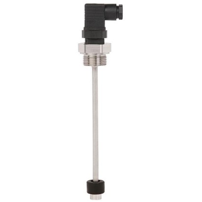
מתג צף
תיאור
ה-RLS-1000 הוא מתג ציפה עמיד, אמין וזול. מאחר שניטור מפלסים וכן הגנת יבש והגנת הצפה הם יישומים רגישים לעלות בתעשיית בניית המכונות, מתג ציפה הוא פתרון אידיאלי עבור מפעלים רבים. ה-RLS-1000 מזהה באופן אמין את מפלס הנוזל במכלים עם מים, שמן, דיזל או נוזלים אחרים באמצעות מגנט קבוע ומגעי קנה ללא חיכוך, עד ל-4 נקודות מיתוג מוגדרות לכל היותר, וניתן להשתמש בו בטווח טמפרטורת מדיום מ- -30 עד +150 °C [-22 עד +302 °F].
מתג הציפה הקומפקטי קל, נוח ומהיר לשילוב, משום שאין צורך לכייל או להגדיר אותו במהלך ההתקנה. הדבר משפר מאוד את קלות הטיפול, במיוחד במצבי התקנה צפופים. בנוסף, מאחר שהמבנה העמיד שלו הופך אותו לעמיד בפני רעידות וזעזועים, עלויות התחזוקה מינימליות.
.
איור משמאל: מחבר זוויתי, ציפה מ-NBR איור מימין: מחבר עגול M12 x 1, ציפה מפלדת אל-חלד
תכונות מיוחדות
- אמינות מרבית בזכות מגעי קנה (reed) איכותיים
- מגוון רחב מאוד ואפשרות לפתרונות לפי דרישות הלקוח
- התקנה פשוטה ומהירה
שאלות ותשובות
מהו טווח המפלס של ה-RLS-1000?
טווח המפלס הוא 0.06 … 1.5 m, עם דיוק של ±3 mm.
כמה נקודות מיתוג יש למתג?
ה-RLS-1000 מציע עד 4 נקודות מיתוג (SP1, SP2, SP3, SP4) באמצעות מגעי קנה ומגנט קבוע.
אילו חיבורי תהליך זמינים?
חיבורים עם הברגה G 1/2 עד G 2 להתקנה מבחוץ, חיבורים G ⅛ עד G ½ להתקנה מבפנים, וכן פלנג'ה DN 50, form B per EN 1092-1 (DIN 2527), PN 16.
מהם חומרי החלקים הבאים במגע עם המדיום?
Stainless steel 316Ti, Buna / NBR, PP ו-PA6.6, בהתאם לדגם.
מהם טווחי הטמפרטורה והלחץ?
טמפרטורת המדיום: -30 … +150 °C; טמפרטורת הסביבה: -30 … +80 °C; הלחץ המרבי של התהליך: 40 bar.
מהו דירוג ההגנה מפני חדירה?
דירוג ההגנה הוא IP65.
האם הדגם מאושר לאזורים עם סיכון פיצוץ?
לא נמסר אישור הגנה מפני פיצוץ עבור ה-RLS-1000; האישורים הזמינים הם RoHS, CE ו-China RoHS.
מה מבדיל את ה-RLS-1000 מדגמים אחרים?
זהו מתג ציפה קומפקטי, קל וזול ללא צורך בכיול או הגדרה בהתקנה, עם עמידות בפני רעידות וזעזועים ועלויות תחזוקה מינימליות — מתאים במיוחד ליישומים רגישים לעלות בבניית מכונות.
| דגם | RLS-1000 |
| סדרה | RLS |
| תת-קטגוריה | Float switch |
| טווח גובה מילוי | 0.06…1.5 m |
| חיבור תהליך | G 1/2, installation from outsideG 3/4, installation from outsideG 1, installation from outsideG 1 ½, installation from outsideG 2, installation from outsideFlange DN 50, form B per EN 1092-1 (DIN 2527), PN 16, installation from outsideG ⅛, installation from insideG ¼, installation from insideG ⅜, installation from insideG ½, installation from insideG 1/2G 3/4G 1G 1 ½G 2G ⅛ BG ¼ BG ⅜ BG ½ BFlange |
| טמפ׳ תהליך | −30…+150 °C |
| לחץ תהליך מירבי | 40 bar |
| טכנולוגיית מדידה | float |
| אות יציאה | SP1 · SP2 · SP3 · SP4 |
| חיבור חשמלי | Angular connector DIN EN 175301-803 A, Circular connector M12 x 1 (4-pin), Cable outlet, Connection housing 'standard', Connection housing 'compact' |
| חומר חלקים רטובים | Stainless steel 316Ti, Buna / NBR, PP, PA6.6 |
| טמפ׳ סביבה | −30…+80 °C |
| דרגת הגנה IP | IP65 |
| תקנים | RoHSCEChina RoHS |
| שפות גיליון נתונים | EN |
| Measuring principle | Potential-free switching reed contacts are triggered by a magnet in the float. | ||
|---|---|---|---|
| Guide tube length L | 60 ... 1,500 mm[2.5 ... 59 in], other lengths on request | ||
| Output signal | Up to 4 switch points, depending on the electrical connection: SP1, SP2, SP3, SP4 | ||
| Switching function | Alternatively normally open (NO), normally closed (NC) or change-over (SPDT) contact - on rising level | ||
| Switch position | Specified in mm, starting from the upper sealing face (SP1 ... SP4) At the end of the guide tube ≈ 45 mm[≈ 1.8 in] cannot be used for switch positions. | ||
| Distance between switch points 1) | Minimum distance SP1 to the upper sealing face: 50 mm[2.0 in] Minimum distance between the switch points: 50 mm[2.0 in], for floats with outer ∅=44mm[1.7 in], 52 mm[2.0 in] 30 mm[1.2 in], for floats with outer ∅=18mm[0.7 in], 22 mm[0.9 in], 25 mm[1.0 in], 30 mm[1.2 in] Minimum distance with 3 switch points: 80 mm[3.1 in], either between SP1 and SP2 or SP2 and SP3 Minimum distance with 4 switch points: 80 mm[3.1 in], between SP2 and SP3 | ||
| Switching power 2) | Floats with outer Normally open, normally closed: Change-over contact: | diameter ∅D=44mm[1.7 in], 52 mm[2.0 in] AC 230 V; 100 VA; 1 A; 50 ... 60 Hz DC 230 V; 50 W;0.5 A AC 230 V; 40 VA; 1 A; 50 ... 60 Hz DC 230 V; 20 W;0.5 A | |
| Floats with outer diameter ∅D=18mm[0.7 in], 22 mm[0.9 in], 25 mm[1.0 in], 30 mm[1.2 in] | |||
| Normally open, normally closed: | AC 100 V; 10 VA; 0.5 A; 50 ... 60 Hz DC 100 V; 10 W;0.5 A | ||
| Change-over contact: | |||
| 100 V; 5 VA; 0.25 A; 50 ... 60 Hz | |||
| DC | AC | 100 V; 5 W;0.25 A | |
| Accuracy | ±3 mmswitch point accuracy incl. hysteresis, non-repeatability | ||
| Mounting position | Vertical ±30° | ||
| Process connection | ■ G1/2, installation from outside 3) ■ G3/4, installation from outside 4) ■ G1, installation from outside ■ G1½, installation from outside | ■ G⅛, installation from inside 5) 6) ■ G¼, installation from inside 5) 6) ■ G⅜, installation from inside 5) ■ G½, installation from inside 5) | |
| steel | on page 3 | ||
| Case | Stainless steel 316Ti | ||
| Non-wetted | |||
| Material | ■ Flange DN | ||
| ■ G2, installation from outside | |||
| 50, form B per EN 1092-1 | |||
| (DIN 2527), PN 16, installation from outside | |||
| Process connection, guide tube Stainless Float See | |||
| table | |||
| table | |||
| Wetted | Electrical | ||
| connection | |||
| 3 | |||
| temperatures | |||
| °F] | |||
| -30 …+80 °C [-22 | |||
| Medium | |||
| -30 …+120 | |||
| Permissible | |||
| …+176 7) 9) | |||
| °C [-22 | |||
| …+248 | °F] | ||
| on page | |||
| 8) 9) | |||
| …+302 °F] | |||
| °C | |||
| [-22 | |||
| -30 …+150 | |||
| See |
| Electrical connections 1) | Max. switch point definition | Ingress protection per IEC/EN 60529 2) | Protection class | Material | Cable length |
|---|---|---|---|---|---|
| Angular connector DIN EN 175301-803 A 3) 4) | ■ 2 NO/NC ■ 1 SPDT | IP65 | II | PA | - |
| Circular connector M12 x 1 (4-pin) 4) | ■ 3 NO/NC ■ 1 NO/NC + 1 SPDT | IP65 | II | TPU, brass | |
| Cable outlet 4) | ■ 4 NO/NC ■ 4 SPDT | IP67 | II | PVC | ■ 2 m[6.5 ft] ■ 5 m[16.4 ft] ■ other |
| Cable outlet 4) | ■ 4 NO/NC ■ 4 SPDT | IP67 | II | PUR | lengths on request |
| Cable outlet 4) | ■ 4 NO/NC ■ 2 NO/NC + 1 SPDT | IP67 | II | Silicone | |
| Cable outlet 'shipbuilding' | ■ 4 NO/NC ■ 4 SPDT | IP67 | II | Polyolefin | |
| Connection housing 'standard' Dimensions: 75 x 80x57mm [3.0 x 3.1 x 2.2 in] For cable diameter: 5 ...10mm [0.2 ... 0.4 in] | ■ 4 NO/NC ■ 4 SPDT | IP66 | I | Case from aluminium, cable gland from polyamide | - |
| Connection housing 'compact' Dimensions: 58 x 64x36mm [2.3 x 2.5 x 1.4 in] For cable diameter: 5 ...10mm [0.2 ... 0.4 in] | ■ 4 NO/NC ■ 2 NO/NC + 1 SPDT ■ 2 SPDT | IP66 | II |
| Float | Form | Outer diameter∅D | Height H | Operating pressure | Medium temperature | Density | Material |
|---|---|---|---|---|---|---|---|
| Cylinder 4) 7) | 44 mm[1.7 in] | 52 mm[2.0 in] | ≤ 16 bar [≤ 232 psi] | -30 ...+150 °C [-22 ...+302 °F] | ≥ 750 kg/m³ [46.8 lbs/ft³] | 316Ti | |
| H | Cylinder 5) | 30 mm[1.2 in] | 36 mm[1.4 in] | ≤ 10 bar [≤ 145 psi] | -30 ...+120 °C [-22 ...+248 °F] | ≥ 850 kg/m³ [53.1 lbs/ft³] | 316Ti |
| ∅D | Cylinder 5) 3) | 25 mm[1.0 in] | 17 mm[0.7 in] | ≤ 16 bar [≤ 232 psi] | -30 ...+80 °C [-22 ...+176 °F] | ≥ 750 kg/m³ [46.8 lbs/ft³] | Buna / NBR |
| Cylinder 4) 6) 9) | 25 mm[1.0 in] | 23 mm[0.9 in] | ≤ 4 bar [≤ 58.0 psi] | -25 ...+80 °C [-13 ...+176 °F] | ≥ 700 kg/m³ [43.7 lbs/ft³] | PP | |
| Cylinder 4) 6) 9) | 25 mm[1.0 in] | 23 mm[0.9 in] | ≤ 4 bar [≤ 58.0 psi] | -25 ...+80 °C [-13 ...+176 °F] | ≥ 750 kg/m³ [46.8 lbs/ft³] | PA6.6 | |
| Cylinder 5) 9) | 22 mm[0.9 in] | 29 mm[1.1 in] | ≤ 16 bar [≤ 232 psi] | -30 ...+120 °C [-22 ...+248 °F] | ≥ 850 kg/m³ [53.1 lbs/ft³] | 316Ti | |
| Cylinder 4) 6) 9) | 18 mm[0.7 in] | 32 mm[1.3 in] | ≤ 16 bar [≤ 232 psi] | -30 ...+80 °C [-22 ...+176 °F] | ≥ 750 kg/m³ [46.8 lbs/ft³] | Buna / NBR | |
| ∅D H | Sphere 6) 7) | 52 mm[2.0 in] | 52 mm[2.0 in] | ≤ 40 bar [≤ 580 psi] | -30 ...+150 °C [-22 ...+302 °F] | ≥ 750 kg/m³ [46.8 lbs/ft³] | 316Ti |
| Normally open/normally closed (NO/NC) | Change-over contact (SPDT) | |
|---|---|---|
| 2 switch points SP1 1 2 SP2 1 3 | 1 switch point SP1 1 2 3 |
הצגת הכול (11)
| Process connection | Dead band inmm | ||||||
|---|---|---|---|---|---|---|---|
| Outer diameter float ∅D | ∅18mm [0.7 in] | ∅22mm [0.9 in] | ∅25mm [1.0 in] | ∅25mm [1.0 in] | ∅30mm [1.2 in] | ∅44mm [1.7 in] | ∅52mm [2.0 in] |
| Float height H | H 32mm [1.3 in] | H 29mm [1.1 in] | H 17mm [0.7 in] | H 23mm [0.9 in] | H 36mm [1.4 in] | H 52mm [2.0 in] | H 52mm [2.0 in] |
| G 1/2 (from outside) | 35 mm[1.4 in] | - | - | - | - | - | - |
| G 3/4 (from outside) | 35 mm[1.4 in] | 35 mm[1.4 in] | - | - | - | - | - |
| G 1 (from outside) | 35 mm[1.4 in] | 35 mm[1.4 in] | 25 mm[1.0 in] | 35 mm[1.4 in] | 35 mm[1.4 in] | - | - |
| G 1 ½(from outside) | - | - | 25 mm[1.0 in] | - | 35 mm[1.4 in] | 45 mm[1.8 in] | - |
| G 2 (from outside) | - | - | 25 mm[1.0 in] | - | 40 mm[1.6 in] | 50 mm[2.0 in] | 50 mm[2.0 in] |
| Flange (from outside) | - | - | 5 mm[0.2 in] | - | 20 mm[0.8 in] | 30 mm[1.2 in] | 30 mm[1.2 in] |
| G ⅛ B (from inside) | 15 mm[0.6 in] | 20 mm[0.8 in] | 15 mm[0.6 in] | 20 mm[0.8 in] | 30 mm[1.2 in] | - | - |
| G ¼ B (from inside) | 20 mm[0.8 in] | 25 mm[1.0 in] | 20 mm[0.8 in] | 25 mm[1.0 in] | 35 mm[1.4 in] | 40 mm[1.6 in] | 40 mm[1.6 in] |
| G ⅜B(from inside) | 20 mm[0.8 in] | 25 mm[1.0 in] | 20 mm[0.8 in] | 25 mm[1.0 in] | 35 mm[1.4 in] | 40 mm[1.6 in] | 40 mm[1.6 in] |
| G ½B(from inside) | 20 mm[0.8 in] | 25 mm[1.0 in] | 20 mm[0.8 in] | 25 mm[1.0 in] | 35 mm[1.4 in] | 45 mm[1.8 in] | 45 mm[1.8 in] |
| G | L 1 | Spanner width |
|---|---|---|
| G 1/2 | 15 mm[0.59 in] | 27 mm[1.1 in] |
| G 3/4 | 15 mm[0.59 in] | 31 mm[1.2 in] |
| G1 | 16 mm[0.63 in] | 41 mm[1.6 in] |
| G1½ | 18 mm[0.71 in] | 30 mm[1.2 in] |
| G2 | 20 mm[0.79 in] | 36 mm[1.4 in] |
| G | L 1 | Spanner width |
|---|---|---|
| G⅛B | 12 mm[0.47 in] | 14 mm[0.5 in] |
| G ¼ B | 12 mm[0.47 in] | 19 mm[0.7 in] |
| G⅜B | 12 mm[0.47 in] | 22 mm[0.9 in] |
| G½B | 14 mm[0.55 in] | 27 mm[1.1 in] |
| Description | Temperature range | Cable diameter | Cable length | Order number | |
|---|---|---|---|---|---|
| Straight version, cut to length, 4-pin, PUR cable, UL listed, IP67 | -20 ...+80 °C [-4 ...+176 °F] | 4.5 mm[0.18 in] | 2 m[6.6 ft] | 14086880 | |
| 5 m[16.4 ft] | 14086883 | ||||
| 10 m[32.8 ft] | 14086884 | ||||
| Angled version, cut to length, 4-pin, PUR cable, UL listed, IP67 | -20 ...+80 °C [-4 ...+176 °F] | 4.5 mm[0.18 in] | 2 m[6.6 ft] | 14086889 | |
| 5 m[16.4 ft] | 14086891 | ||||
| 10 m[32.8 ft] | 14086892 |
| Logo | Description | Country |
|---|---|---|
| EU declaration of conformity ■ Low voltage directive ■ RoHS directive | European Union | |
| DNV GL (option) 1) Ships, shipbuilding (e.g. offshore) | International |
| Logo | Description |
|---|---|
| - | China RoHS directive |
| Re- placed model | Current model | Description |
|---|---|---|
| EX-SR 10 | RLS-4000 | Float switch, stainless steel, terminal housing, ATEX approval |
| EX-SR 11 | RLS-4000 | Float switch, stainless steel, cable outlet, ATEX approval |
| EX-SR 13 | RLS-4000 | Compact float switch, stainless steel, terminal housing, ATEX approval |
| EX-SR 14 | RLS-4000 | Compact float switch, stainless steel, cable outlet, ATEX approval |
| EX-SR 20 | RLS-4000 | Compact angled float switch, stainless steel, cable outlet, ATEX approval |
| EX-SR 21 | RLS-4000 | Compact angled float switch, stainless steel, cable outlet, ATEX approval |
| SR 6 | RLS-5000 | Bilge float switch |
| SR 10 | RLS-1000 | Float switch, stainless steel, terminal housing |
| SR 11 | RLS-1000 | Float switch, stainless steel, cable outlet |
| SR 12 | RLS-1000 | Float switch, stainless steel, connector |
| SR 13 | RLS-1000 | Compact float switch, stainless steel, terminal housing |
| SR 14 | RLS-1000 | Compact float switch, stainless steel, cable outlet |
| SR 20 | RLS-1000 | Angled float switch, stainless steel, cable outlet |
| SR 30 | RLS-2000 | Float switch, plastic, terminal housing |
| SR 31 | RLS-2000 | Float switch, plastic, cable outlet |
| SR 32 | RLS-2000 | Float switch, plastic, connector |
| SR 33 | RLS-2000 | Angled float switch, plastic, cable outlet |
| SR 71 | RLS-1000 | Compact float switch, stainless steel, cable outlet |
| SR 80 | RLS-6000 | Suspended float switch, switch rod activated, reed switch |
| TN 210 | RLS-3000 | Float switch, stainless steel, terminal housing, integrated temperature switch |
| TN 211 | RLS-3000 | Float switch, stainless steel, cable outlet, integrated temperature switch |
| TN 230 | RLS-3000 | Float switch, stainless steel, terminal housing, integrated Pt100 temperature output signal |
| TN 231 | RLS-3000 | Float switch, stainless steel, cable outlet, integrated Pt100 temperature output signal |
לא מצאתם תשובה בתיעוד? מהנדס יענה במהלך יום עסקים.
שאלו מהנדס →1 מק״טים סטנדרטיים של משפחת RLS
אם ידוע הקוד — בחרו ישירות. אם לא — השתמשו בתצורה במצב «01».