
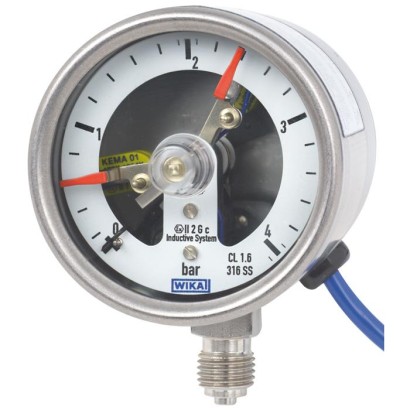
Bourdon tube pressure gauge with switch contacts
Description
Wherever the process pressure has to be indicated locally and, at the same time, circuits need to be switched, this switchGAUGE finds its use.
Switch contacts (electrical switch contacts) make or break an electric control circuit dependent upon the pointer position of the indicating measuring instrument. The switch contacts are adjustable over the full extent of the scale range (see DIN 16085), and are mounted predominantly below the dial, though also partly on top of the dial. The instrument pointer (actual value pointer) moves freely across the entire scale range, independent of the setting.
The set pointer can be adjusted using a removable adjustment key in the window.
For further approvals, see page 11
Model PGS23.063 with switch contact model 830 E.21
Switch contacts consisting of 2 contacts can also be set to a single set point. Contact actuation is made when the actual value pointer travels beyond or below the desired set point.
The pressure gauge is manufactured in accordance with all requirements of the relevant international standards and regulations for the on-site indication of the working pressure of pressure vessels.
As switch contacts, magnetic snap-action contacts, reed switches, inductive contacts and electronic contacts are available. Inductive contacts can be used in hazardous areas. For triggering programmable logic controllers (PLC), electronic contacts and reed switches can be used.
Special features
- Up to 2 switch contacts per instrument
- Instruments with inductive contacts for use in hazardous areas
- Instruments with contacts for PLC applications
- Safety version with solid baffle wall (Solidfront)
Build a PGS23.063 for your task
The article number is assembled automatically. If unsure — ask an engineer; we'll match the line's parameters.
- ModelPGS23
- Nominal size063
- switchmagnetic snap action switch, model 821
- first switch operationmakes (1)
- second switch operationwithout
- Explosion protectionwithout
- Electrical connection2 m cable
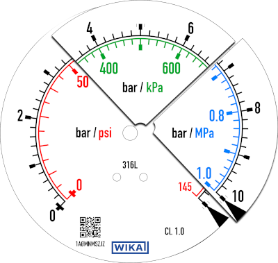
- Unit of outer Scalebar
- Measuring rangegauge pressure range
- Scale range0...4 bar
- 2nd Scale or Special Scale—
- Process connection—
- Connection location—
- Casesolid front design EN837 "S3"
- Mounting optionwithout
- Restrictorwithout
- Pressure Gauge StandardInternational (standard Europe)
- Special design featureswithout
- Certificateswithout
- Approvalswithout
- Additional ordering informationWithout
Finish your configuration
Select every option to submit the request.
| Model | PGS23.063 |
| Product family | PGS23 |
| Subcategory | Switch gauge with electrical contacts |
| Pressure ranges | 0…4 bar · 0…6 bar · 0…7 bar · 0…10 bar · 0…14 bar · 0…16 bar · 0…20 bar · 0…25 bar · 0…30 bar · 0…40 bar · 0…0.4 MPa · 0…0.6 MPa · 0…0.7 MPa · 0…1 MPa · 0…1.4 MPa · 0…1.6 MPa · 0…2 MPa · 0…2.5 MPa · 0…3 MPa · 0…4 MPa · 0…60 psi · 0…100 psi · 0…150 psi · 0…160 psi · 0…200 psi · 0…250 psi · 0…300 psi · 0…400 psi · 0…500 psi · -1…3 bar · -1…10 bar · -1…4 bar · -1…15 bar · -1…5 bar · -1…24 bar · -1…7 bar · -1…30 bar · -1…9 bar · -100…300 kPa · -100…1000 kPa · -100…400 kPa · -100…1500 kPa · -100…500 kPa · -100…2400 kPa · -100…700 kPa · -100…3000 kPa · -100…900 kPa · -0.1…0.3 MPa · -0.1…1 MPa · -0.1…0.4 MPa · -0.1…1.5 MPa · -0.1…0.5 MPa · -0.1…2.4 MPa · -0.1…0.7 MPa · -0.1…3 MPa · -0.1…0.9 MPa · 0…7 MPa · 0…400 kPa · 0…600 kPa · 0…700 kPa · 0…800 kPa · 0…1000 kPa · 0…1400 kPa · 0…1600 kPa · 0…2500 kPa · 0…3000 kPa · 0…4000 kPa · 0…60 bar · 0…70 bar · 0…100 bar · 0…140 bar · 0…160 bar · 0…200 bar · 0…250 bar · 0…315 bar · 0…400 bar · 400…6000 kPa · 600…7000 kPa · 700…8000 kPa · 800…10000 kPa · 1000…14000 kPa · 1400…16000 kPa · 1600…20000 kPa · 2500…25000 kPa · 3000…31500 kPa · 4000…40000 kPa · 0…10 MPa · 0…14 MPa · 0…16 MPa · 0…20 MPa · 0…25 MPa · 0…31.5 MPa · 0…40 MPa · 0…600 psi · 0…800 psi · 0…1000 psi · 0…1500 psi · 0…2000 psi · 0…3000 psi · 0…4000 psi · 0…5000 psi · 0…6000 psi · -30…60 inHg · -30…200 inHg · -30…100 inHg · -30…300 inHg · -30…160 inHg |
| Accuracy class | 1.6 |
| Accuracy standard | EN 837-1 |
| Process connection | G ¼ BG ½ BR ¼R ½¼ NPT½ NPTG 1/8 BG 1/4 BR 1/8R 1/41/8 NPT1/4 NPT |
| Process temperature | −20…+100 °C |
| Output signal | Magnetic snap-action contact · Inductive contact · Electronic contact · Reed switch |
| Electrical connection | Cable, length 2 m, PVC |
| Switching function | Normally open, normally closed, change-over |
| Switching contacts | 2 |
| Case material | Stainless steel 1.4301 (304), Stainless steel 1.4571 (316 Ti) |
| Wetted parts material | Stainless steel 1.4404 (316L), Monel 400 (2.4360), Stainless steel |
| Sealing material | Polycarbonate, Laminated safety glass |
| Ambient temperature | −20…+60 °C |
| IP rating | IP54 |
| Weight | 0.6 kg |
| Certifications | CERoHS |
| Explosion protection | II 2G Ex ia IIC T6/T5/T4 GbII 2D Ex ia IIIB T135°C DbGas II 2G Ex ia IIC T6/T5/T4 GbDust II 2D Ex ia IIIB T135℃ DbGas Ex ia IIC T6/T5/T4 GbDust Ex ia IIIB T135℃ Db |
| Dial size | 63 mm |
| Datasheet languages | EN |
| bar | |
|---|---|
| 0 ... 4 | 0 ... 60 |
| 0 ... 6 | 0 ... 70 |
| 0 ... 7 | 0 ... 100 |
| 0 ... 10 | 0 ... 140 |
| 0 ... 14 | 0 ... 160 |
| 0 ... 16 | 0 ... 200 |
| 0 ... 20 | 0 ... 250 |
| 0 ... 25 | 0 ... 315 |
| 0 ... 30 | 0 ... 400 |
| 0 ... 40 | - |
| kPa | |
|---|---|
| 0 ... 400 | 0 ... 6,000 |
| 0 ... 600 | 0 ... 7,000 |
| 0 ... 700 | 0 ... 8,000 |
| 0 ... 800 | 0 ... 10,000 |
| 0 ... 1,000 | 0 ... 14,000 |
| 0 ... 1,400 | 0 ... 16,000 |
| 0 ... 1,600 | 0 ... 20,000 |
| 0 ... 2,500 | 0 ... 25,000 |
| 0 ... 3,000 | 0 ... 31,500 |
| 0 ... 4,000 | 0 ... 40,000 |
| psi | |
|---|---|
| 0 ... 60 | 0 ... 600 |
| 0 ... 100 | 0 ... 800 |
| 0 ... 150 | 0 ... 1,000 |
| 0 ... 160 | 0 ... 1,500 |
| 0 ... 200 | 0 ... 2,000 |
| 0 ... 250 | 0 ... 3,000 |
| 0 ... 300 | 0 ... 4,000 |
| 0 ... 400 | 0 ... 5,000 |
| 0 ... 500 | 0 ... 6,000 |
| 0 ... 4 | 0 ... 60 |
|---|---|
| 0 ... 6 | 0 ... 70 |
| 0 ... 7 | 0 ... 100 |
| 0 ... 10 | 0 ... 140 |
| 0 ... 14 | 0 ... 160 |
| 0 ... 16 | 0 ... 200 |
| 0 ... 20 | 0 ... 250 |
| 0 ... 25 | 0 ... 315 |
| 0 ... 30 | 0 ... 400 |
| 0 ... 40 | - |
View all (20)
| 0 ... 0.4 | 0 ... 7 |
|---|---|
| 0 ... 0.6 | 0 ... 7 |
| 0 ... 0.7 | 0 ... 10 |
| 0 ... 1 | 0 ... 14 |
| 0 ... 1.4 | 0 ... 16 |
| 0 ... 1.6 | 0 ... 20 |
| 0 ... 2 | 0 ... 25 |
| 0 ... 2.5 | 0 ... 31.5 |
| 0 ... 3 | 0 ... 40 |
| 0 ... 4 | - |
| bar | |
|---|---|
| -1 ...+3 | -1 ...+10 |
| -1 ...+4 | -1 ...+15 |
| -1 ...+5 | -1 ...+24 |
| -1 ...+7 | -1 ...+30 |
| -1 ...+9 | - |
| -100 ...+300 | -100 ... +1,000 |
|---|---|
| -100 ...+400 | -100 ... +1,500 |
| -100 ...+500 | -100 ... +2,400 |
| -100 ...+700 | -100 ... +3,000 |
| -100 ...+900 | - |
| -30 inHg ...+60 | -30 inHg ...+200 |
|---|---|
| -30 inHg ...+100 | -30 inHg ...+300 |
| -30 inHg ...+160 | - |
| Special scale ranges | Other scale ranges on request |
|---|---|
| Unit | ■ bar ■ psi ■ kg/cm² ■ kPa ■ MPa |
| Increased overload safety | ■ Without ■ 2 times |
| Vacuum resistance | ■ Without ■ Vacuum-resistant to -1 bar |
| Dial | |
| Scale colour | Black |
| Material | Aluminium |
| Special scale | ■ Without ■ With temperature scale for refrigerant, e.g. for NH 3 :R 717 |
| Other scales, e.g. with red mark, circular arcs or circular sectors, on request → Alternatively, adhesive label set for red and green circular arcs, see data sheet AC08.03 | |
| Pointer | |
| Instrument pointer | Aluminium, black |
| Set pointer | Aluminium, red |
| -1 ...+3 | -1 ...+10 |
|---|---|
| -1 ...+4 | -1 ...+15 |
| -1 ...+5 | -1 ...+24 |
| -1 ...+7 | -1 ...+30 |
| -1 ...+9 | - |
| -0.1 ... +0.3 | -0.1 ...+1 |
|---|---|
| -0.1 ... +0.4 | -0.1 ... +1.5 |
| -0.1 ... +0.5 | -0.1 ... +2.4 |
| -0.1 ... +0.7 | -0.1 ...+3 |
| -0.1 ... +0.9 | - |
| Process connection | ||
|---|---|---|
| Standard | ■ EN 837-1 ■ ISO 7 ■ ANSI/B1.20.1 | |
| Size | ||
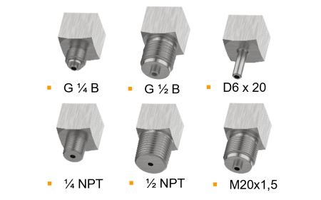
| EN 837-1 | ■ G¼B,male thread ■ G½B,male thread | |
| ISO 7 | ■ R ¼, male thread ■ R ½, male thread | |
| ANSI/B1.20.1 | ■ ¼NPT, male thread ■ ½NPT, male thread | |
| Restrictor | ■ Without ■ ∅0.6 mm[0.024"], stainless steel ■ ∅0.3 mm[0.012"], stainless steel ■ ∅0.6 mm[0.024"], Monel | |
| Material (wetted) | ||
| Process connection | Model PGS23 | Stainless steel 1.4404 (316L) |
| Model PGS26 | Monel 400 (2.4360) | |
| Bourdon tube | Model PGS23 | Stainless steel 1.4404 (316L) |
| Model PGS26 | Monel 400 (2.4360) |
| Output signal | |
|---|---|
| Type of contact | ■ Magnetic snap-action contact, model 821, see page 6 ■ Inductive contact, model 831, see page 7 ■ Electronic contact, model 830 E, see page 8 ■ Reed switch, model 851, see page 9 |
| Switching technology | |
| Magnetic snap-action contact, model 821 | ■ No control unit and no supply voltage required ■ Direct switching up to 250 V, 1 A |
| Inductive contact, model 831 | ■ Suitable for use in hazardous areas with corresponding control unit (model 904.xx) ■ Long service life due to non-contact sensor ■ Low influence on the indication accuracy ■ Fail-safe switching at high switching frequency ■ Insensitive to corrosion ■ Also available in safety version |
| Electronic contact, model 830 E | ■ For direct triggering of a programmable logic controller (PLC) ■ Long service life due to non-contact sensor ■ Low influence on the indication accuracy ■ Fail-safe switching at high switching frequency ■ Insensitive to corrosion |
| Reed switch, model 851 | ■ No control unit and no supply voltage required ■ Direct switching up to 250 V, 1 A ■ For direct triggering of a programmable logic controller (PLC) ■ Free from wear as without contact |
| Contact setting | ■ Contact(s) adjustable, adjustment key attached to cable socket ■ Contact(s) fixed, without adjustment lock 1) ■ Adjustment lock sealable (tamper-proof) ■ Adjustment lock sealed (tamper-proof) 1) ■ Captive adjustment key with the adjustment lock connected |
| Type of contact | Magnetic snap-action contact |
|---|---|
| Switching technology | ■ No control unit and no supply voltage required ■ Direct switching up to 250 V, 1 A |
| Number of switch contacts | Max. 2 switch contacts |
| Switching function | ■ Separate circuits with ≥ 2 switches ■ Cable break monitoring with parallel resistance (47 kΩ or 100 kΩ) The switching function of each switch is indicated by index 1, 2 or 3 |
| Model 821.1 | Normally open (clockwise pointer motion) |
| Model 821.2 | Normally closed (clockwise pointer motion) |
| Model 821.3 | Change-over contact; one contact breaks and one contact makes simultaneously when pointer reaches set point |
| Switch point setting | Set pointers of the contact pressure gauges are freely adjustable over the full scale range |
| Setting range (recommended) | 25 ... 75 %of span 1) |
| Distance between switch points | Recommended minimum distance between 2 contacts: 20 %of span |
| Switch hysteresis | 2 ... 5 %(typical) |
| Switching current | 0.02 ... 0.3 A (resistive load) Permissible switch-on and switch-off current: ≤ 0.5 A |
| Switching voltage 2) | AC/DC 24 ...250V |
| Switching power | |
| Unfilled instruments | ≤ 30 W, ≤ 50VA |
| Filled instruments | ≤ 20 W, ≤ 20VA |
| Contact material | Silver-nickel, gold-plated |
| Switching voltage | Unfilled instruments | Filled instruments | ||||
|---|---|---|---|---|---|---|
| Resistive load | Inductive load | Resistive load | Inductive load | |||
| Direct current | Alternating current | cos ϕ>0.7 | Direct current | Alternating current | cos ϕ>0.7 | |
| DC 220 V / AC 230 V | 100mA | 120mA | 65mA | 65mA | 90mA | 40mA |
| DC 110 V / AC 110 V | 200mA | 240mA | 130mA | 130mA | 180mA | 85mA |
| DC 48 V / AC 48 V | 300mA | 450mA | 200mA | 190mA | 330mA | 130mA |
| DC 24 V / AC 24 V | 400mA | 600mA | 250mA | 250mA | 450mA | 150mA |
| Type of contact | Inductive contact |
|---|---|
| Switching technology | ■ Suitable for use in hazardous areas with corresponding control unit (model 904.xx) ■ Long service life due to non-contact sensor ■ Low influence on the indication accuracy ■ Fail-safe switching at high switching frequency ■ Insensitive to corrosion ■ Safety version available |
| Number of switch contacts | Max. 2 switch contacts |
| Switching function | Contact versions: ■ 831-N ■ 831-SN, safety version 1) ■ 831-S1N, safety version 1) , inverted signal |
| The switching function of each switch is indicated by index 1 or 2 | |
| Model 831.1 | Normally open (clockwise pointer motion) |
| Model 831.2 | Normally closed (clockwise pointer motion) |
| Switch point setting | Set pointers of the contact pressure gauges are freely adjustable over the full scale range |
| Setting range (recommended) | 10 ... 90 %of span (0 ... 100 %onrequest) |
| Distance between switch points | 2 contacts can be set to an identical set point. |
| Switching current | Depending on the control unit used, see data sheet AC 08.04 |
| Switching voltage | Depending on the control unit used, see data sheet AC 08.04 |
| Switching power | Depending on the control unit used, see data sheet AC 08.04 |
| Permissible temperature ranges in hazardous areas | |
| T6 | -20 ...+60 °C |
| T5 ...T1 | -20 ...+70 °C |
| T135°C | -20 ...+70 °C |
| Model | Version | Ex version |
|---|---|---|
| 904.28 KFA6 - SR2 - Ex1.W | 1 contact | Yes |
| 904.29 KFA6 - SR2 - Ex2.W | 2 contacts | Yes |
| 904.30 KHA6 - SH - Ex1 | 1 contact | Yes - Safety version |
| 904.33 KFD2 - SH - Ex1 | 1 contact | Yes - Safety version |
| 904.25 MSR 010-I | 1 contact | No |
| 904.26 MSR 020-I | 2 contacts | No |
| 904.27 MSR 011-I | Two-point control | No |
| Type of contact | Electronic contact (PNP transistor) |
|---|---|
| Switching technology | ■ For direct triggering of a programmable logic controller (PLC) ■ Long service life due to non-contact sensor ■ Low influence on the indication accuracy ■ Fail-safe switching at high switching frequency ■ Insensitive to corrosion |
| Number of switch contacts | Max. 2 switch contacts |
| Switching function | Contact versions: ■ 2-wire system ■ 3-wire system |
| The switching function of each switch is indicated by index 1 or 2 | |
| Model 830 E.1 | Normally open (clockwise pointer motion) |
| Model 830 E.2 | Normally closed (clockwise pointer motion) |
| Setting range (recommended) | 10 ... 90 %of span 1) |
| Distance between switch points | 2 contacts can be set to an identical set point. |
| Switching current | ≤ 100mA |
| Switching voltage | DC 10 ...30V |
| Type of contact | Bistable reed switch |
|---|---|
| Switching technology | ■ No control unit and no supply voltage required ■ Direct switching up to 250 V, 1 A ■ For direct triggering of a programmable logic controller (PLC) ■ Free from wear as without contact |
| Number of switch contacts | 1 switch contact |
| Switching function | The switching function of the switch is indicated by index 1, 2 or 3 |
| Model 851.1 | Normally open (clockwise pointer motion) |
| Model 851.2 | Normally closed (clockwise pointer motion) |
| Model 851.3 | Change-over contact; one contact breaks and one contact makes simultaneously when pointer reaches set point |
| Switch point setting | Set pointers of the contact pressure gauges are freely adjustable over the full scale range |
| Setting range (recommended) | 10 ... 90 %of span |
| Switch hysteresis | 3 ...5% |
| Switching current | ≤ AC/DC 1 A |
| Switching voltage | ≤ AC/DC 250V |
| Switching power | ≤ 60 W, 60VA |
| Contact material | Rhodium |
| Transport current | AC/DC 2 A |
| Inductive load cosϕ | 1 |
| Contact resistance (static) | 100mΩ |
| Insulation resistance | 10 9 Ω |
| Breakdown voltage | DC 1,000V |
| Switching time incl. contact chatter | 4.5 ms |
| Logo | Description | Region |
|---|---|---|
| EU declaration of conformity | European Union | |
| EMCdirective | ||
| RoHS directive | ||
| - | CRN Safety (e.g. electr. safety, overpressure, ...) | Canada |
Couldn't find the answer in the documentation? An engineer will reply within a business day.
Ask an engineer →132 standard articles of family PGS23
If you know the code — pick directly. If not — use the configurator in mode “01”.