
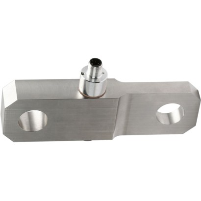
Tension link
Description
Tension links are designed for static and dynamic measurement tasks in the direct flux of force. As a load-bearing component in existing constructions, they determine the tension forces in a wide scope of applications.
Tension links of these models are often used in hoist and crane systems as torque support or rope fix point for load measurements. Further application areas are special machine constructions, e. g. in polymer processing machines.
Appropriate technical and regional approvals are available as an option.
For further approvals see page 4
Fig. above: Tension link, model F7301
Fig. below: Tension link, model F73C1
The tension links of the model F73x1 are either made of high-strength, corrosion-resistant stainless steel 1.4542 or robust fine-grained steel with surface protection. Due to their properties, these materials are particularly suitable for the applications of tension links.
As output signals, the common active current and voltage outputs are available (4 … 20 mA, 0 … 10 V). Redundant output signals and CANopen ® protocols are also possible.
These force transducers can be integrated into a certified WIKA overload protection with model ELMS1 (DIN EN ISO 13849-1 with PL d/cat. 3).
Special features
- Measurement ranges from 0 ... 5 kN [0 ... 1,124 lbf]
- Fine-grained structural steel with high-quality surface protection or in corrosion-resistant stainless steel version
- High long-term stability, high shock and vibration resistance, excellent reproducibility
- For dynamic and static measurements
- Redundant output signal is possible
| Models | F7301 and F73C1 with UL | F73S1 |
|---|---|---|
| Rated force F nom kN [lbf] | ≥ 5 [≥ 1,124] | |
| Relative linearity error d lin 1) | ±0.5%F nom | |
| Relative repeatability error in unchanged mounting position b rg | ±0.5%F nom | |
| Temperature effect on | ||
| characteristic valueTK c | 0.2%F nom /10 K | |
| zero signalTK 0 | 0.2%F nom /10 K | |
| Force limit F L | 150%F nom | |
| Breaking force F | 300%F nom | |
| B Shear force influence d Q (Signal with 100%F nom under 90°) 2) | ±2%F nom | |
| Rated displacement (typ.) s nom | < 0.1 mm[< 0.004 in] | |
| Material of measuring device | ■ Corrosion-resistant stainless steel, 1.4542, ultrasound-tested 3,1 material ■ Version with 3,2 material available | |
| Rated temperature B T, nom | -20 …+80 °C [-4 ...+176 °F] | |
| Operating temperature B T, G | -30 …+80 °C [-22 ...+176 °F] | -30 …+80 °C [-22 ...+176 °F] |
| Storage temperature B T, S | -40 …+85 °C [-40 ...+185 °F] | |
| Electrical connection | ■ Circular connector M12 x 1, 4-pin or 5-pin ■ CANopen ® Circular connector M12 x 1, 5-pin ■ MIL connector | ■ 2-circular connector M12x1, 4-pin ■ MIL connector |
| Output signal (rated output) C nom | ■ 4 …20mA, 2-wire, ■ 4 …20mA, 3-wire ■ 2 x 4 …20mA, redundant ■ DC 0 …10V, 3-wire ■ DC 2 x 0 …10Vredundant ■ Signal jump 4 ... 16 mA, 2-wire 5) DC 2 ... 8 V, 3-wire 5) ■ CANopen ® Protocol in accordance with CiA ® 301, device profile CiA ® 404, communication services LSS (CiA ® 305), configuration of the instrument address and baud rate Sync/Async, Node/ Lifeguarding, heartbeat; zero and span ±10% 3) | Redundant opposing 4…20mA/20…4mA Version in accordance with requirements for functional safety per machinery directive 2006/42/EC asWIKA overload protection with model ELMS1 (DIN EN ISO 13849-1 with PL d/cat. 3). |
| Current consumption | ■ Current output 4 …20mA, 2-wire: signal current ■ Current output 4 …20mA, 3-wire:<8mA ■ Voltage output:<8mA ■ CANopen ® :<1W | Current output 4 …20mA, 2-wire: signal current |
| Supply voltage UB | ■ DC 9 ...36V for current output ■ DC 13 ...36V for voltage output ■ DC 9 ...36V for CANopen ® | DC 10 …30Vfor current output |
| Burden | ■ ≤ (UB - 10 V) / 0.024 A for current output ■ > 10 kΩ for voltage output | ■ ≤ (UB - 10 V) / 0.020 A (channel 1) for current output ■ ≤ (UB - 7 V) / 0.020 A (channel 2) for current output |
| Response time | ≤ 2 ms (within 10 ...90%F nom ) 4) | |
| Protection (per EN/IEC 60529) | ||
| Unplugged condition | IP66, IP67 | IP67 |
| Plugged condition | IP68, IP69, IP69K | |
| Electrical protection | Reverse voltage, overvoltage and short-circuit protection | |
| Vibration resistance | 20 g, 100 h, 50...150 Hz (acc. to DIN EN 60068-2-6) | |
| Shock resistance | In accordance with DIN EN 60068-2-27 | |
| Immunity | ■ In accordance with DIN EN 61326-1/DIN EN 61326-2-3 ■ EMC-strengthened version |
| Models | F73C1 ATEX/IECEx EX ib 1) |
|---|---|
| Rated force F nom kN [lbf] | ≥ 5 [≥ 1,124] |
| Relative linearity error d lin 2) | ±0.5%F nom |
| Relative repeatability error in unchanged mounting position b rg | ±0.5%F nom |
| Temperature effect on | |
| characteristic valueTK c | 0.2%F nom /10 K |
| zero signalTK 0 | 0.2%F nom /10 K |
| Force limit F L | 150%F nom |
| Breaking force F B | 300%F nom |
| Shear force influence d Q (Signal with 100% F nom under 90°) 3) | ±2%F nom |
| Rated displacement (typ.) s nom | < 0.1 mm[< 0.004 in] |
| Material of measuring device | ■ Corrosion-resistant stainless steel, 1.4542, ultrasound-tested 3,1 material ■ Version with 3,2 material available |
| Rated temperature B T, nom | -20 …+80 °C [-4 ...+176 °F] |
| Operating temperature B T, G | Ex II 2G Ex ib IIC T4 Gb -25 °C <Tamb < +85 °C Ex II 2G Ex ib IIC T3 Gb -25 °C <Tamb < +100 °C Ex I M2 Ex ib I Mb -25 °C <Tamb < +85 °C Ex II 2G Ex ib IIC T4 Gb -40 °C <Tamb < +85 °C Ex I M2 Ex ib I Mb |
| Storage temperature B T, S | -40 …+85 °C [-40 ...+185 °F] |
| Electrical connection | ■ Circular connector M12x1, 4-pin ■ MIL connector ■ Cable gland |
| Output signal (rated output) C nom | 4 …20mA, 2-wire |
| Current consumption | Current output 4 …20mA2-wire:signal current |
| Supply voltage UB | DC 10 ...30V for current output |
| Burden | ■ < (UB - 10 V) / 0,024 A for current output ■ > 10 kΩ for voltage output |
| Response time | ≤ 2 ms (within 10 ...90%F nom ) 4) |
| Protection (acc. to EN/IEC 60529) | IP67 |
| Electrical protection | Reverse voltage, overvoltage and short-circuit protection |
| Shock resistance | 20 g, 100 h, 50...150 Hz acc. to DIN EN 60068-2-6 |
| Immunity | ■ In accordance with DIN EN 61326-1/DIN EN 61326-2-3 ■ EMC-strengthened version |
| Logo | Description | Region |
|---|---|---|
| EU declaration of conformity EMCdirective | European Union |
| Logo | Description | Region |
|---|---|---|
| ATEX directive 1) per EN 60079-0:2012 and EN 60079-11:2012 (Ex ib) Hazardous areas Ex ib Ex II 2G Ex ib IIC T4 Gb -25 °C <T amb < +85 °C Ex II 2G Ex ib IIC T3 Gb -25 °C <T amb < +100 °C Ex I M2 Ex ib I Mb 3) -25 °C <T amb < +85 °C Ex II 2G Ex ib IIC T4 Gb -40 °C <T amb < +85 °C | European Union | |
| IECEx 2) per IEC 60079-0:2011 (Ed. 6) and IEC 60079-11:2011 (Ed. 6) (Ex ib) Hazardous areas Ex ib Ex ib IIC T4/T3 Gb -25 °C <T amb < +85 °C Ex ib IIC T4 Gb -25 °C <T amb < +100 °C Ex ib I Mb 3) -25 °C <T amb < +85 °C Ex ib IIC T4 Gb -40 °C <T amb < +85 °C | International | |
| UL 2) per UL 61010-1 and CSA C22.2 Number 61010-1 Component approval | USA and Canada | |
| EAC EMCdirective | Eurasian Economic Community | |
| EAC Ex 1) Hazardous areas Ex ib Ex ib IIC T3 Gb -40 °C <Tamb < +100 °C Ex ib IIC T3 Gb -45 °C <Tamb < +100 °C Ex ib IIC T4 Gb -40 °C <Tamb < +85 °C Ex ib IIC T4 Gb -45 °C <Tamb < +100 °C | Eurasian Economic Community |
View all (20)
| Signal | Description |
|---|---|
| UB | Voltage source for sensor |
| UB+ | Sensor-supply voltage (+) |
| UB- | Sensor-supply voltage (-) |
| S+ | Output signal (+) |
| S- | Output signal (-) |
| 0 V | 0V potential |
| Signal | Description |
|---|---|
| A | Ammeter |
| V | Voltmeter |
| + - | Voltage source |
| Switch | |
| Shield (grounding) |
| Signal | 4 ... 20 mA, 2-wire | Cable colour |
|---|---|---|
| UB+/S+ | 1 | Brown |
| 0 V/S- | 3 | Black |
| Shield | Case/connector | - |
| Signal | 4 ... 20 mA, 3-wire | Cable colour |
|---|---|---|
| UB+ | 1 | Brown |
| S+ | 4 | Black |
| 0 V/S- | 3 | Blue |
| Shield | Case/connector | - |
| Signal | 0 ... 10 V, 3-wire | Cable colour |
|---|---|---|
| UB+ | 1 | Brown |
| S+ | 4 | Black |
| 0 V/S- | 3 | Blue |
| Shield | Case/connector | - |
| Signal | Description |
|---|---|
| UB | Voltage source for sensor |
| UB+ | Sensor-supply voltage (+) |
| UB- | Sensor-supply voltage (-) |
| UR | Voltage source for den signal jump |
| UR+ | Signal jump-supply voltage (+) |
| UR- | Signal jump-supply voltage (-) |
| S+ | Output signal (+) |
| S- | Output signal (-) |
| 0 V | 0V potential |
| Signal | Description |
|---|---|
| A | Ammeter |
| V | Voltmeter |
| + - | Voltage source |
| Switch | |
| Shield (grounding) |
| Signal | 4 ... 20 mA, 2-wire | Cable colour |
|---|---|---|
| UB+/S+ | 1 | Brown |
| 0 V/S- | 3 | Blue |
| UR+ | 2 | White |
| UR- | 4 | Black |
| Shield | Case/connector | - |
| Signal | 4 ... 20 mA, 3-wire | Cable colour |
|---|---|---|
| UB+ | 1 | Brown |
| 0 V/S- | 3 | Blue |
| UR+ | 2 | White |
| UR- | 3 | Blue |
| S+ | 4 | Black |
| Shield | Case/connector | - |
| Signal | 0 ... 10 V, 3-wire | Cable colour |
|---|---|---|
| UB+ | 1 | Brown |
| 0 V/S- | 3 | Blue |
| UR+ | 2 | White |
| UR- | 3 | Blue |
| S+ | 4 | Black |
| Shield | Case/connector | - |
| Signal | Description |
|---|---|
| UB | Voltage source for sensor |
| UB+ | Sensor-supply voltage (+) |
| UB- | Sensor-supply voltage (-) |
| S+ | Output signal (+) |
| S- | Output signal (-) |
| CH1 | Channel 1 |
| CH2 | Channel 2 |
| CH1+2 | Channel 1 and channel 2 |
| 0 V | 0V potential |
| Signal | Description |
|---|---|
| A | Ammeter |
| V | Voltmeter |
| + - | Voltage source |
| Switch | |
| Shield (grounding) |
| Signal | 4 ... 20 mA, 2-wire | Cable colour |
|---|---|---|
| UB+/S+ (CH1) | 1 | Brown |
| UB+/S+ (CH2) | 2 | White |
| 0 V/S- (CH1) | 3 | Blue |
| 0 V/S- (CH2) | 4 | Black |
| Shield | Case/connector | - |
| Signal | 4 ... 20 mA, 3-wire | Cable colour |
|---|---|---|
| UB+ (CH1+2) | 1 | Brown |
| 0 V/S- (CH1+2) | 3 | Blue |
| S+ (CH1) | 4 | Black |
| S+ (CH2) | 2 | White |
| Shield | Case/connector | - |
| Signal | 0 ... 10 V, 3-wire | Cable colour |
|---|---|---|
| UB+ (CH1+2) | 1 | Brown |
| 0 V/S- (CH1+2) | 3 | Blue |
| S+ (CH1) | 4 | Black |
| S+ (CH2) | 2 | White |
| Shield | Case/connector | - |
| Signal | Description |
|---|---|
| UB | Voltage source for sensor |
| UB+ | Sensor-supply voltage (+) |
| UB- | Sensor-supply voltage (-) |
| S+ | Output signal (+) |
| S- | Output signal (-) |
| CH1 | Channel 1 |
| CH2 | Channel 2 |
| CH1+2 | Channel 1 and channel 2 |
| 0 V | 0V potential |
Couldn't find the answer in the documentation? An engineer will reply within a business day.
Ask an engineer →