
WIKA · Pressure measurement · Family 712
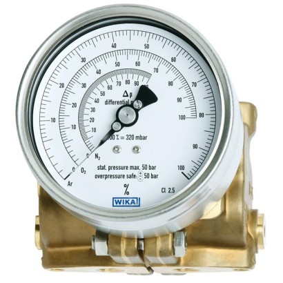
Differential pressure gauge
Cryo Gauge, copper alloy or stainless steel, NS 100
Range
0…1725 mbar
Output
4-20mA
Accuracy
2.5
Protection
IP65
CEGOSTKazInMetrMTSCHSBelGIMUzstandardCPACRNBAMEACEMCPEDEx ia IIC T6/T5/T4 GbII 2G Ex ia IIC T6/T5/T4 Gb
Price
On request
Depends on configuration
Description
These high-quality differential pressure gauges are notable for their compact and robust design and are primarily used for level measurement on liquid gas tanks.
With 11 different measuring cells, all usual tank sizes in cryotechnology are covered. The large overlap in measuring ranges of the measuring cells enables the setting for gas types such as Ar, O 2 , N 2 or CO 2 over the entire scale with 270 angular degrees. The span adjustment is accessible from outside and does not affect the zero point.
for further approvals see page 4
Special features
- Differential pressure measuring ranges from 0 … 80 mbar to 0 ... 1725 mbar
- High working pressure (static pressure) of 50 bar
- Overpressure safety either side up to 50 bar
- Very compact design
- Optionally compact valve manifold with working pressure indication
Identification
| Model | 712.15.100 |
| Product family | 712 |
| Subcategory | Differential pressure gauge |
Measuring range
| Pressure ranges | 0…40 mbar · 0…60 mbar · 0…90 mbar · 0…120 mbar · 0…165 mbar · 0…240 mbar · 0…330 mbar · 0…480 mbar · 0…660 mbar · 0…975 mbar · 0…1350 mbar · 0…1725 mbar |
Accuracy
| Accuracy class | 2.5 |
Process conditions
| Process connection | 2 x G ¼, female, centre distance 37 mm2 x ¼ NPT, female, centre distance 37 mmG1/4, female, centre distance 37 mm1/4 NPT, female, centre distance 37 mm |
| Process temperature | −40…+80 °C |
Electrical characteristics
| Output signal | 4-20mA |
| Power supply | DC 12 V < U ≤ 30 V |
| Electrical connection | Cable socket PA 6, black Per VDE 0110 insulation group C/250 V, Cable gland M20 x 1.5, 6 screw terminals + PE for conductor cross-section 2.5 mm² |
| Switching function | Contact makes the circuit when the set point is exceeded; Contact breaks the circuit when the set point is exceeded; Change-over contact |
| Switching contacts | 2 |
Materials
| Case material | Stainless steel |
| Wetted parts material | Copper alloy CW614N (CuZn39Pb3), Stainless steel 316L, Stainless steel 1.4310, NBR, Stainless steel 1.4301, Stainless steel 1.4305 |
| Sealing material | NBR, PTFE |
Operating environment
| Ambient temperature | −40…+80 °C |
| IP rating | IP65 |
Certifications and approvals
| Certifications | CEGOSTKazInMetrMTSCHSBelGIMUzstandardCPACRNBAMEACEMCPED |
| Explosion protection | Ex ia IIC T6/T5/T4 GbII 2G Ex ia IIC T6/T5/T4 Gb |
Additional details
| Dial size | 100 mm |
| Datasheet languages | EN, DE |
Tables from datasheet
Models 712.15.100 and 732.15.100
| Nominal size inmm | 100 |
|---|---|
| Accuracy class | 2.5 Option: ■ 1.6 ■ 1.0 |
| Scale ranges | Measuring cell 60 mbar: Setting range 0 …40mbar to 0 …60mbar Measuring cell 90 mbar: Setting range 0 …60mbar to 0 …90mbar Measuring cell 120 mbar: Setting range 0 …80mbar to 0 …120 mbar Measuring cell 165 mbar: Setting range 0 …110 mbar to 0 …165 mbar Measuring cell 240 mbar: Setting range 0 …160 mbar to 0 …240 mbar Measuring cell 330 mbar: Setting range 0 …220 mbar to 0 …330 mbar Measuring cell 480 mbar: Setting range 0 …320 mbar to 0 …480 mbar Measuring cell 660 mbar: Setting range 0 …440 mbar to 0 …660 mbar Measuring cell 975 mbar: Setting range 0 …650 mbar to 0 …975 mbar Measuring cell 1,350 mbar: Setting range 0 …900 mbar to 0 …1,350 mbar Measuring cell 1,725 Setting range 0 …1,150 mbar to 0 …1,725 mbar |
| Scale | Single scale Option: Individual scale design |
| Zero point setting | By means of adjustable pointer |
| Overload safety and max. working pressure (static pressure) | Either side max. 50 bar |
| Connection location | Lower mount (radial) |
| Process connection | ■ 2xG ¼ , female, centre distance37mm ■ 2 x ¼ NPT, female, centre distance37mm others on request Option: Adapter for process connection, see page 6 |
| Wetted materials | |
| Measuring cell flanges | Model 712.15: Copper alloy CW614N (CuZn39Pb3) Model 732.15: Stainless steel 316L |
| Compression spring | Stainless steel 1.4310 |
| Separating diaphragm | NBR |
| Transmission parts | Stainless steel 1.4301 and 1.4305 |
| Non-wetted materials | |
| Case | Stainless steel |
| Bayonet ring | Stainless steel |
| Movement | Stainless steel |
| Dial | Aluminium, white |
| Pointer | Adjustable pointer, black aluminium |
| Window | Polycarbonate (PC) |
| Ingress protection per IEC/EN 60529 | IP65 |
| Mounting | According to affixed symbols ⊕high pressure, ⊖low pressure |
| Non-Ex version: Models 712.15.100 and 732.15.100 optionally with model 891.44 1) | Ex version: Models 712.15.100 and 732.15.100 with model 892.44 1) | |
|---|---|---|
| Ambient | -40 …+60 °C with oxygen -40 …+80 °C | -40 ...+60 °C for temperature class T6 and T5 -40 ...+80 °C for temperature class T4 |
| Medium | -40 …+60 °C with oxygen -40 …+80 °C | -40 …+60 °C with oxygen -40 ...+60 °C for temperature class T6 and T5 -40 ...+80 °C for temperature class T4 |
| Logo | Description | Country |
|---|---|---|
| EU declaration of conformity ■ EMCdirective ■ Pressure equipment directive ■ ATEX directive (option) 1) Hazardous areas - Ex ia Gas [II 2G Ex ia IIC T6/T5/T4 | European Union | |
| IECEx (option) 1) Hazardous areas - Ex ia Gas [Ex ia IIC T6/T5/T4 Gb] | International | |
| EAC (option) ■ EMCdirective ■ Pressure equipment directive ■ Low voltage directive ■ Hazardous areas 1) | Eurasian Economic Community | |
| GOST (option) Metrology, measurement technology | Russia | |
| KazInMetr (option) Metrology, measurement technology | Kazakhstan | |
| - | MTSCHS (option) Permission for commissioning | Kazakhstan |
| BelGIM (option) Metrology, measurement technology | Belarus | |
| Uzstandard (option) Metrology, measurement technology | Uzbekistan | |
| - | CPA Metrology, measurement technology | China |
| - | CRN Safety (e.g. electr. safety, overpressure, ...) | Canada |
| BAM Oxygen application | Germany |
Specifications
| Valves | 2 x shut-off valve, 1 x pressure compensating valve |
|---|---|
| Test connection | M20 x 1.5 with sealing cap (DIN 16287-A) |
| Valve body | ■ Copper alloy CW614N (CuZn39Pb3) for model 712.15 ■ Stainless steel 316L for model 732.15 |
| Spindle with conical nipple | ■ Copper alloy for model 712.15 ■ Stainless steel 316L for model 732.15 |
| Packing/sealing | NBR/PTFE With the valve fully-opened, the spindle area is isolated from the process by a metallic seal, the packing is not loaded and the spindle thread is not in contact with the measured media. |
| Working pressure indication | ■ Bourdon tube pressure gauges, stainless steel, models 232.50.63 and 232.50.100, see data sheet PM02.02 ■ Bourdon tube pressure gauge, stainless steel, safety version; model 232.30.100; see data sheet PM02.04 ■ Bourdon tube pressure gauge, copper alloy; model 212.20.100; see data sheet PM02.01 |
View all (6)
Specifications
| Material | ■ Copper alloy CW614N (CuZn39Pb3) for model 712.15 ■ Stainless steel 316L for model 732.15 |
|---|---|
| Process connections (wetted) | 2 x G¼, female, centre distance 31 mmor 54 mmor 2 x ¼NPT, female, centre distance 31mmor54mm |
| Specifications | 891.44 and 892.44 | |
|---|---|---|
| Output signal | 4 …20mA, 2-wire | |
| Supply voltage U B | Non-Ex version, model 891.44:DC 12V < U B ≤ 30V Ex version, model 892.44:DC 14V < U B ≤ 30V | |
| Influence of supply voltage | ≤ 0.1 %of full scale/10V | |
| Permissible residual ripple | ≤ 10 %ss | |
| Permissible max. load R A | RA ≤ (U B - 12 V)/0.02 A with R A in Ωand U B in V, however max.600Ω | |
| Effect of load | ≤ 0.1 %of full scale | |
| Adjustability | ||
| Zero point, electrical | Adjustment of the zero point through brief bridging of terminals 5 and 6 or using the 'scale selection switch' option, selectable via button 1) | |
| Scale selection | 4 scales selectable via BCD switch | |
| Linear error | ≤ 1.0 %of span (terminal method) | |
| Compensated temperature range | -40 …+80 °C | |
| Temperature coefficients in the compensated temperature range | ||
| MeanTC zero point | ≤ 0.3 %of span/10 K | |
| MeanTC span | ≤ 0.3 %of span/10 K | |
| Electrical connection | Cable socket PA 6, black PerVDE 0110 insulation group C/250V Cable gland M20 x 1.5 Strain relief 6 screw terminals + PE for conductor cross-section 2.5 mm² | |
| Electrical safety Ingress protection | Protection against reverse polarity and overvoltage IP65 per EN/IEC 60529 | |
| Safety-related maximum values for Ex version, model 892.44 | ||
| Supply voltage U i | DC 14 ...30V | |
| Short-circuit current I i | ≤ 100mA | |
| Power P i | ≤ 720mW | |
| Internal capacitance C i | ≤ 17.5 nF | |
| Internal inductance L i | negligible | |
| Designation of connection terminals, 2-wire | Do not use this terminal | Terminals 3, 4, 5 and 6: For internal use only |
| UB+/Sig | Connection must not be used for equipotential bonding.The instrument must be incorporated in the equipotential bonding via the process connection. | |
| +0 V/Sig- |
Application areas not described yet
Describe your operating conditions — our engineer will suggest a model and use case.
Couldn't find the answer in the documentation? An engineer will reply within a business day.
Ask an engineer →