
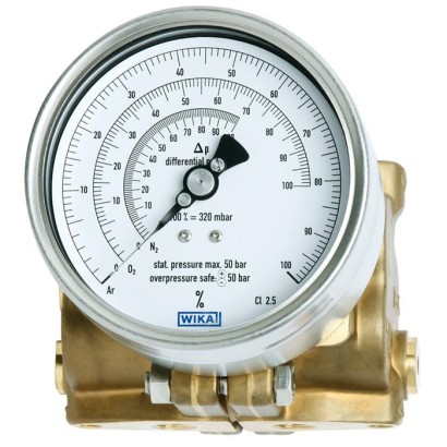
מד לחץ הפרשי
תיאור
מדדי הפרש לחץ איכותיים אלה בולטים בתכנון קומפקטי וחסון, ומשמשים בעיקר למדידת מפלס במכלי גז נוזלי.
עם 11 תאי מדידה שונים, מכוסים כל גדלי המכלים המקובלים בתחום הקריוטכנולוגיה. החפיפה הגדולה בטווחי המדידה של תאי המדידה מאפשרת כיוון לסוגי גזים כגון Ar, O 2 , N 2 או CO 2 על פני כל הסקאלה באמצעות 270 מעלות זווית. כיוון הטווח נגיש מבחוץ ואינו משפיע על נקודת האפס.
ללאישורים נוספים ראה עמוד 4
תכונות מיוחדות
- טווחי מדידת לחץ דיפרנציאלי מ-0 … 80 mbar עד 0 ... 1725 mbar
- לחץ עבודה גבוה (לחץ סטטי) של 50 bar
- בטיחות מפני לחץ יתר משני הצדדים עד 50 bar
- תכנון קומפקטי מאוד
- אופציונלי: סעפת שסתומים קומפקטית עם אינדיקציית לחץ עבודה
שאלות ותשובות
מהו טווח המדידה של המד?
המד מוצע ב-11 טווחי מדידה הפרשיים, מ-0 … 40 mbar ועד 0 … 1725 mbar, עם חפיפה גדולה בין הטווחים.
מהי מחלקת הדיוק של המד?
מחלקת הדיוק היא 2.5.
מהו לחץ העבודה הסטטי המותר?
לחץ העבודה (הלחץ הסטטי) הוא 50 bar, וקיימת בטיחות יתר-לחץ משני הצדדים עד 50 bar.
אילו חיבורי תהליך זמינים?
חיבורים נקביים 2 x G ¼ או 2 x ¼ NPT, במרחק בין מרכזים של 37 mm.
מהם חומרי החלקים במגע עם התווך?
סגסוגת נחושת CW614N (CuZn39Pb3), נירוסטה 316L, 1.4310, 1.4301 או 1.4305, עם איטום NBR או PTFE — כלומר מתאים לתווכים גזיים ונוזליים שאינם צמיגים מאוד.
מהם טווחי הטמפרטורה המותרים?
טמפרטורת הסביבה וטמפרטורת התווך: -40 … +80 °C.
מהו דירוג ההגנה מפני חדירה?
המד מדורג IP65.
האם המד מאושר לאזורים עם סיכון פיצוץ?
כן, קיימים אישורי פיצוץ Ex ia IIC T6/T5/T4 Gb ו-II 2G Ex ia IIC T6/T5/T4 Gb, בנוסף לאישורים CE, EAC, CRN, BAM ואחרים.
| דגם | 712.15.100 |
| סדרה | 712 |
| תת-קטגוריה | Differential pressure gauge |
| טווח לחץ | 0…40 mbar · 0…60 mbar · 0…90 mbar · 0…120 mbar · 0…165 mbar · 0…240 mbar · 0…330 mbar · 0…480 mbar · 0…660 mbar · 0…975 mbar · 0…1350 mbar · 0…1725 mbar |
| מחלקת דיוק | 2.5 |
| חיבור תהליך | 2 x G ¼, female, centre distance 37 mm2 x ¼ NPT, female, centre distance 37 mmG1/4, female, centre distance 37 mm1/4 NPT, female, centre distance 37 mm |
| טמפ׳ תהליך | −40…+80 °C |
| אות יציאה | 4-20mA |
| הזנה | DC 12 V < U ≤ 30 V |
| חיבור חשמלי | Cable socket PA 6, black Per VDE 0110 insulation group C/250 V, Cable gland M20 x 1.5, 6 screw terminals + PE for conductor cross-section 2.5 mm² |
| פונקציית מתג | Contact makes the circuit when the set point is exceeded; Contact breaks the circuit when the set point is exceeded; Change-over contact |
| מגעי מתג | 2 |
| חומר מארז | Stainless steel |
| חומר חלקים רטובים | Copper alloy CW614N (CuZn39Pb3), Stainless steel 316L, Stainless steel 1.4310, NBR, Stainless steel 1.4301, Stainless steel 1.4305 |
| חומר אטם | NBR, PTFE |
| טמפ׳ סביבה | −40…+80 °C |
| דרגת הגנה IP | IP65 |
| תקנים | CEGOSTKazInMetrMTSCHSBelGIMUzstandardCPACRNBAMEACEMCPED |
| הגנת התפוצצות | Ex ia IIC T6/T5/T4 GbII 2G Ex ia IIC T6/T5/T4 Gb |
| קוטר חוגה | 100 mm |
| שפות גיליון נתונים | EN, DE |
| Nominal size inmm | 100 |
|---|---|
| Accuracy class | 2.5 Option: ■ 1.6 ■ 1.0 |
| Scale ranges | Measuring cell 60 mbar: Setting range 0 …40mbar to 0 …60mbar Measuring cell 90 mbar: Setting range 0 …60mbar to 0 …90mbar Measuring cell 120 mbar: Setting range 0 …80mbar to 0 …120 mbar Measuring cell 165 mbar: Setting range 0 …110 mbar to 0 …165 mbar Measuring cell 240 mbar: Setting range 0 …160 mbar to 0 …240 mbar Measuring cell 330 mbar: Setting range 0 …220 mbar to 0 …330 mbar Measuring cell 480 mbar: Setting range 0 …320 mbar to 0 …480 mbar Measuring cell 660 mbar: Setting range 0 …440 mbar to 0 …660 mbar Measuring cell 975 mbar: Setting range 0 …650 mbar to 0 …975 mbar Measuring cell 1,350 mbar: Setting range 0 …900 mbar to 0 …1,350 mbar Measuring cell 1,725 Setting range 0 …1,150 mbar to 0 …1,725 mbar |
| Scale | Single scale Option: Individual scale design |
| Zero point setting | By means of adjustable pointer |
| Overload safety and max. working pressure (static pressure) | Either side max. 50 bar |
| Connection location | Lower mount (radial) |
| Process connection | ■ 2xG ¼ , female, centre distance37mm ■ 2 x ¼ NPT, female, centre distance37mm others on request Option: Adapter for process connection, see page 6 |
| Wetted materials | |
| Measuring cell flanges | Model 712.15: Copper alloy CW614N (CuZn39Pb3) Model 732.15: Stainless steel 316L |
| Compression spring | Stainless steel 1.4310 |
| Separating diaphragm | NBR |
| Transmission parts | Stainless steel 1.4301 and 1.4305 |
| Non-wetted materials | |
| Case | Stainless steel |
| Bayonet ring | Stainless steel |
| Movement | Stainless steel |
| Dial | Aluminium, white |
| Pointer | Adjustable pointer, black aluminium |
| Window | Polycarbonate (PC) |
| Ingress protection per IEC/EN 60529 | IP65 |
| Mounting | According to affixed symbols ⊕high pressure, ⊖low pressure |
| Non-Ex version: Models 712.15.100 and 732.15.100 optionally with model 891.44 1) | Ex version: Models 712.15.100 and 732.15.100 with model 892.44 1) | |
|---|---|---|
| Ambient | -40 …+60 °C with oxygen -40 …+80 °C | -40 ...+60 °C for temperature class T6 and T5 -40 ...+80 °C for temperature class T4 |
| Medium | -40 …+60 °C with oxygen -40 …+80 °C | -40 …+60 °C with oxygen -40 ...+60 °C for temperature class T6 and T5 -40 ...+80 °C for temperature class T4 |
| Logo | Description | Country |
|---|---|---|
| EU declaration of conformity ■ EMCdirective ■ Pressure equipment directive ■ ATEX directive (option) 1) Hazardous areas - Ex ia Gas [II 2G Ex ia IIC T6/T5/T4 | European Union | |
| IECEx (option) 1) Hazardous areas - Ex ia Gas [Ex ia IIC T6/T5/T4 Gb] | International | |
| EAC (option) ■ EMCdirective ■ Pressure equipment directive ■ Low voltage directive ■ Hazardous areas 1) | Eurasian Economic Community | |
| GOST (option) Metrology, measurement technology | Russia | |
| KazInMetr (option) Metrology, measurement technology | Kazakhstan | |
| - | MTSCHS (option) Permission for commissioning | Kazakhstan |
| BelGIM (option) Metrology, measurement technology | Belarus | |
| Uzstandard (option) Metrology, measurement technology | Uzbekistan | |
| - | CPA Metrology, measurement technology | China |
| - | CRN Safety (e.g. electr. safety, overpressure, ...) | Canada |
| BAM Oxygen application | Germany |
| Valves | 2 x shut-off valve, 1 x pressure compensating valve |
|---|---|
| Test connection | M20 x 1.5 with sealing cap (DIN 16287-A) |
| Valve body | ■ Copper alloy CW614N (CuZn39Pb3) for model 712.15 ■ Stainless steel 316L for model 732.15 |
| Spindle with conical nipple | ■ Copper alloy for model 712.15 ■ Stainless steel 316L for model 732.15 |
| Packing/sealing | NBR/PTFE With the valve fully-opened, the spindle area is isolated from the process by a metallic seal, the packing is not loaded and the spindle thread is not in contact with the measured media. |
| Working pressure indication | ■ Bourdon tube pressure gauges, stainless steel, models 232.50.63 and 232.50.100, see data sheet PM02.02 ■ Bourdon tube pressure gauge, stainless steel, safety version; model 232.30.100; see data sheet PM02.04 ■ Bourdon tube pressure gauge, copper alloy; model 212.20.100; see data sheet PM02.01 |
הצגת הכול (6)
| Material | ■ Copper alloy CW614N (CuZn39Pb3) for model 712.15 ■ Stainless steel 316L for model 732.15 |
|---|---|
| Process connections (wetted) | 2 x G¼, female, centre distance 31 mmor 54 mmor 2 x ¼NPT, female, centre distance 31mmor54mm |
| Specifications | 891.44 and 892.44 | |
|---|---|---|
| Output signal | 4 …20mA, 2-wire | |
| Supply voltage U B | Non-Ex version, model 891.44:DC 12V < U B ≤ 30V Ex version, model 892.44:DC 14V < U B ≤ 30V | |
| Influence of supply voltage | ≤ 0.1 %of full scale/10V | |
| Permissible residual ripple | ≤ 10 %ss | |
| Permissible max. load R A | RA ≤ (U B - 12 V)/0.02 A with R A in Ωand U B in V, however max.600Ω | |
| Effect of load | ≤ 0.1 %of full scale | |
| Adjustability | ||
| Zero point, electrical | Adjustment of the zero point through brief bridging of terminals 5 and 6 or using the 'scale selection switch' option, selectable via button 1) | |
| Scale selection | 4 scales selectable via BCD switch | |
| Linear error | ≤ 1.0 %of span (terminal method) | |
| Compensated temperature range | -40 …+80 °C | |
| Temperature coefficients in the compensated temperature range | ||
| MeanTC zero point | ≤ 0.3 %of span/10 K | |
| MeanTC span | ≤ 0.3 %of span/10 K | |
| Electrical connection | Cable socket PA 6, black PerVDE 0110 insulation group C/250V Cable gland M20 x 1.5 Strain relief 6 screw terminals + PE for conductor cross-section 2.5 mm² | |
| Electrical safety Ingress protection | Protection against reverse polarity and overvoltage IP65 per EN/IEC 60529 | |
| Safety-related maximum values for Ex version, model 892.44 | ||
| Supply voltage U i | DC 14 ...30V | |
| Short-circuit current I i | ≤ 100mA | |
| Power P i | ≤ 720mW | |
| Internal capacitance C i | ≤ 17.5 nF | |
| Internal inductance L i | negligible | |
| Designation of connection terminals, 2-wire | Do not use this terminal | Terminals 3, 4, 5 and 6: For internal use only |
| UB+/Sig | Connection must not be used for equipotential bonding.The instrument must be incorporated in the equipotential bonding via the process connection. | |
| +0 V/Sig- |
לא מצאתם תשובה בתיעוד? מהנדס יענה במהלך יום עסקים.
שאלו מהנדס →