
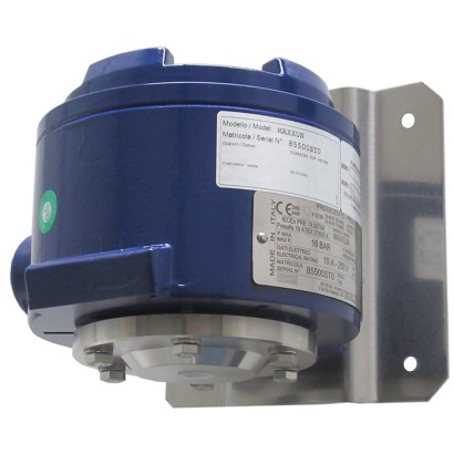
Реле давления с мембраной, взрывозащищённое исполнение в корпусе с видом взрывозащиты Ex d
Описание
Эти высококачественные механические реле давления разработаны специально для применений, где требуется повышенная надёжность в системах безопасности. Большое преимущество механических реле давления заключается в том, что для процесса переключения не требуется напряжение питания.
В производстве переключатели на каждом этапе отслеживаются программным обеспечением системы обеспечения качества и впоследствии подвергаются 100 % испытаниям. Прочный корпус реле из алюминиевого сплава способен выдерживать жёсткие и коррозионно-агрессивные условия эксплуатации в процессной промышленности при диапазонах рабочих давлений до 600 bar. Реле давления оснащено 1 или 2 микропереключателями, что позволяет выполнять прямое переключение электрической нагрузки до AC 250 V, 20 A.
Для более низких значений коммутируемой мощности, например для применений с ПЛК, доступны микропереключатели, заполненные аргоном, с позолоченными контактами.
Особенности
- Прочный корпус выключателя из алюминиевого сплава, IP66, NEMA 4X
- Диапазоны уставок от 16 мбар до 600 бар, а также все прочие эквивалентные вакуумные или комбинированные диапазоны давления и вакуума
- 1 или 2 независимых коммутационных порога, высокая коммутируемая мощность до AC 250 В, 20 А
- Повторяемость точки переключения < 1 %
Вопросы и ответы
Какой диапазон давлений охватывает реле MA?
Диапазоны уставок — от 16 mbar до 600 bar; доступны также эквивалентные вакуумметрические и комбинированные диапазоны «давление–вакуум», например −1 … 15 bar.
Какая точность у этого прибора?
Воспроизводимость точки переключения составляет < 1 %, класс точности ≤ 1 % диапазона по IEC 61298-2:2008.
Какие варианты присоединения к процессу доступны?
¼ NPT и ½ NPT (внутренняя резьба), G ¼ A и G ½ A (наружная резьба), M20x1.5, G 1/2 B, а также фланцы ASME B16.5 Class 150/300/600 и EN 1092-1 PN 10/40.
Для каких сред подходит реле?
Прибор предназначен для газообразных и жидких, агрессивных и высоковязких или загрязнённых сред; части, контактирующие со средой, изготавливаются из Stainless steel 316/316L, Monel, Hastelloy C276, PTFE, FPM или NBR.
Какой температурный диапазон допускается?
Температура окружающей среды и рабочей среды — от −60 до +85 °C.
Какая взрывозащита предусмотрена?
Корпус с видом взрывозащиты Ex d: Ex db IIC T6/T4 Gb и Ex tb IIIC T85/T135 Db; сертификаты ATEX, IECEx, UKCA, EAC, CCC, INMETRO и другие.
Какова степень защиты корпуса?
IP66 и NEMA 4X; корпус — безмедный алюминиевый сплав с акриловым покрытием.
Чем модель MA отличается от соседних моделей семейства?
Модели MAB и MAG имеют маркировку II 1/2 GD, модель MAH — II 2 GD; все модели доступны в исполнении Ex db IIC T6/T4.
| Модель | MA |
| Подтип | Diaphragm pressure switch |
| Диапазон давления | 0…40 bar · 0…0.016 bar · 0…0.2 bar · 0…0.4 bar · 0…1 bar · 0…1.2 bar · 0…2.5 bar · 0…6 bar · 0…10 bar · 0…16 bar · 0…25 bar · 4…40 bar · 10…100 bar · 10…250 bar · 20…400 bar · 30…600 bar · -0.1…0.1 bar · -0.5…0.5 bar · -1…0 bar · -1…1.5 bar · -1…5 bar · -1…9 bar · -1…15 bar · -0.2…0 bar · -0.4…0 bar · -12.5…12.5 mbar · -30…30 mbar · -50…50 mbar · 0…100 mbar |
| Класс точности | ≤ 1 % of span |
| Стандарт точности | IEC 61298-2:2008 |
| Уровень функциональной безопасности (SIL) | SIL 2-qualified, SIL 3-qualified |
| Технологическое присоединение | ¼ NPT, female thread½ NPT, female thread via adapter½ NPT, male thread via adapterG ¼, female thread via adapterG ½ A, male thread via adapterG ¼ A, male thread via adapterASME B16.5 FlangeEN 1092-1 FlangeG 1/2 BM20x1.51/2 NPTASME B16.5 Class 150/300/600EN 1092-1 PN 10/401/4 NPT, female thread1/2 NPT, female thread via adapter1/2 NPT, male thread via adapterG1/4, female thread via adapterG1/2 A, male thread via adapterG1/4 A, male thread via adapterASME B16.51EN 1092-1 |
| Темп. процесса | −60…+85 °C |
| Электр. соединение | ½ NPT female (standard), ¾ NPT, Gk ½, Gk ¾, M20 x 1.5 female, Cable gland non-armoured, Ex d, nickel-plated brass, Cable gland armoured, Ex d, AISI 304 |
| Функция переключения | 1 or 2 independent switch points, SPDT, DPDT |
| Переключающие контакты | 2 |
| Материал корпуса | Aluminium alloy, copper-free, painted with acrylic paint |
| Материал смачиваемых частей | Stainless steel 316, PTFE, Stainless steel 316L, Monel, Hastelloy C276, FPM, NBR |
| Материал уплотнения | FPM, NBR, PTFE, welded diaphragm |
| Темп. окружающей среды | −60…+85 °C |
| Степень защиты IP | IP66 |
| Вес | 3.1 kg |
| Сертификаты | NACE MR0175/ISO 15156NACE MR0103/ISO 17945EN 1854EN 12952EN 12953CERoHSEAC |
| Взрывозащита | II 1/2 GD (models MAB, MA, MAG)II 2 GD (model MAH)Ex db IIC T6/T4Gb, Ex tb IIIC T85/T135 Db (models MAB, MA, MAG)Gb, Ex tb IIIC T85/T135 Db (model MAH)ATEXIECExUKCAEACEx UkraineCCCINMETROKCsECASEx dEx db IIC T6/T4 Ga/GbEx tb IIIC T85/T135 DbEx db IIC T6/T4 Gb |
| Языки datasheet | EN |
| Basic information | |
|---|---|
| Version | Diaphragm pressure switch, flameproof enclosure Ex d |
| Special design feature | ■ For oxygen, oil- and grease-free ■ Per NACE 1) MR0175 / ISO 15156, use in H₂S-containing environments in oil and gas production ■ Per NACE 1) MR0103 / ISO 17945, metals resistant to sulphide stress cracking ■ Version compliant with EN 1854, pressure sensing devices for gas burners and gas burning appliances ■ Version compliant with EN 12952 and EN 12953, limiting devices in water- tube and shell boilers ■ Drying of wetted parts ■ Offshore version ■ Tropical version (suitable for environments with increased air humidity) ■ Version for ammonia applications ■ Geothermal version ■ Low-temperature version to -60 °C ■ Assembled as a diaphragm seal system ■ Additional protection from stainless steel 316L or Hastelloy for setting ranges 2.5 ... 25 bar |
| Contact version | →See table 'Contact version' |
| Function | ■ 1 x SPDT (single pole double throw) ■ 2 x SPDT (single pole double throw) ■ 1 x DPDT (double pole double throw) The DPDT function is realised with 2 simultaneously triggering SPDT microswitches, within 0.2 %of span. |
| Dead band | ■ 1 or 2 contacts with fixed dead band ■ 1 or 2 contacts with adjustable dead band ■ 1 contact with fixed dead band and 1 contact with adjustable dead band |
| Dielectric strength | Safety class I (IEC 61298-2: 2008) |
| Switch enclosure | |
| Design | Housing cover can be secured against unauthorised access with screw locking. Laser-engraved product label from stainless steel. |
| Material | Aluminium alloy, copper-free, painted with acrylic paint |
| Mounting 2) | ■ Direct mounting ■ Wall bracket from stainless steel AISI 304 ■ Mounting bracket for 2" pipe mounting from stainless steel AISI 304 |
| Contact version | Electrical rating (resistive load) | ||
|---|---|---|---|
| AC | DC | ||
| With fixed dead band | |||
| UN | 1 x SPDT, silver | 250 V, 15 A | 24 V, 2 A, 125 V, 0.5 A, 220 V, 0.25 A |
| US | 1 x SPDT, silver, hermetically sealed, argon gas filling 1) | 250 V, 15 A | 24 V, 2 A, 220 V, 0.5 A |
| UO | 1 x SPDT, gold-plated, hermetically sealed, argon gas filling 1) | 125 V, 1 A | 24 V, 0.5 A |
| UG | 1 x SPDT, gold-plated | 125 V, 1 A | 24 V, 0.5 A |
| DN | 2 x SPDT or 1 x DPDT, silver | 250 V, 15 A | 24 V, 2 A, 125 V, 0.5 A, 220 V, 0.25 A |
| DS | 2 x SPDT or 1 x DPDT, silver, hermetically sealed, argon gas filling 1) | 250 V, 15 A | 24 V, 2 A, 220 V, 0.5 A |
| DO | 2 x SPDT, or 1 x DPDT gold-plated, hermetically sealed, argon gas filling 1) | 125 V, 1 A | 24 V, 0.5 A |
| DG | 2 x SPDT or 1 x DPDT, gold-plated | 125 V, 1 A | 24 V, 0.5 A |
| Contact version | Electrical rating (resistive load) | ||
|---|---|---|---|
| AC | DC | ||
| With adjustable dead band | |||
| UR | 1 x SPDT, silver | 250 V, 20 A | 24 V, 2 A, 220 V, 0.5 A |
| RR 3) | 2 x SPDT or 1 x DPDT, silver | 250 V, 15 A | 24 V, 2 A, 220 V, 0.5 A |
| With fixed dead band and adjustable dead band | |||
| DR 3) | 2 x SPDT, silver (1 x UN + 1 x UR) | 250 V, 15 A | 24 V, 2 A, 220 V, 0.5 A |
| Sensor element | Model | Wetted parts | Permissible medium temperature 1) | ||
|---|---|---|---|---|---|
| Sensor element | Process connection | ||||
| Setting range 0 …16mbar to 0 …40bar | |||||
| XX 2) | Diaphragm element | MAB,MA | Stainless steel 316 3) | Stainless steel 316L | -30 ...+85 °C |
| TX | Diaphragm element | MAB,MA | Stainless steel 316 3) + PTFE 4) | Stainless steel 316L | -30 ...+85 °C |
| TT | Diaphragm element | MAB,MA | Stainless steel 316 3) + PTFE 4) | Stainless steel 316L + PTFE | -30 ...+85 °C |
| KK 2) | Diaphragm element | MAB,MA | Monel 5) | Monel | -30 ...+85 °C |
| KX 2) | Diaphragm element | MAB,MA | Monel 5) | Stainless steel 316L | -30 ...+85 °C |
| Setting range 4 …40bar to 30 …600 bar | |||||
| GXX 6) | Piston with welded diaphragm element | MAG | Hastelloy C276 | Stainless steel 316L | -40 ...+85 °C |
| HXX 7) | Piston with O-ring sealing from FPM | MAH | Stainless steel 316 | Stainless steel 316L | 0 ... 85 °C |
| Piston with O-ring sealing from NBR | MAH | Stainless steel 316 | Stainless steel 316L | -10 ...+85 °C |
Смотреть все (20)
| Set point repeatability | ≤ 1 %of span of setting range |
|---|---|
| Dead band | →See table 'Setting range' |
| Standard | Variant 1 | Variant 2 | Dead band | |||||
|---|---|---|---|---|---|---|---|---|
| Setting range (= working range) | Proof pressure | Working range | Proof pressure | Working range | Proof pressure | 1 contact, fixed | 2 contacts, fixed | 1 contact, adjustable |
| in mbar | in bar | in mbar | in mbar | in mbar | ||||
| in bar | in bar | in bar | ||||||
| 0 ... 16 | 250 | 0 ... 8 | 10 | -1 ... 8 1) | 10 | ≤ 2.0 | ≤ 2.8 | - |
| 0…25 | 250 | 0 ... 8 | 10 | -1 ... 8 1) | 10 | ≤ 2.0 | ≤ 3 | 8 …18 |
| 0…40 | 300 | 0…8 | 10 | -1 ... 8 1) | 10 | ≤ 2.6 | ≤ 3.4 | 8…20 |
| 0 ... 60 | 300 | 0…8 | 10 | -1 ... 8 1) | 10 | ≤ 3.0 | ≤ 4.2 | 12…25 |
| 0 ... 100 | 600 | 0…8 | 10 | -1 ... 8 1) | 10 | ≤ 3.6 | ≤ 5 | 17…40 |
| Standard | Variant 1 | Variant 2 | Dead band | |||||
|---|---|---|---|---|---|---|---|---|
| Setting range (= working range) | Proof pressure | Working range | Proof pressure | Working range | Proof pressure | 1 contact, fixed | 2 contacts, fixed | 1 contact, adjustable |
| in mbar | in bar | in bar | in bar | in bar | in mbar | in mbar | in mbar | |
| -16 ... 0 | -21 | -1…0 1) | 0.25 | - | - | ≤ 2.0 | ≤ 2.8 | - |
| -25 ... 0 | -35 | -1…0 1) | 0.25 | - | - | ≤ 2.0 | ≤ 3 | 8…18 |
| -40 ... 0 | -55 | -1…0 1) | 0.30 | - | - | ≤ 2.6 | ≤ 3.4 | 8…20 |
| -60 ... 0 | -90 | -1…0 1) | 0.30 | - | - | ≤ 3.0 | ≤ 4.2 | 12…25 |
| -100 ... 0 | -150 | -1…0 1) | 0.40 | - | - | ≤ 3.6 | ≤ 5 | 17…40 |
| -12.5 ... +12.5 | -25 / 250 | - | - | - | - | ≤ 2.0 | ≤ 3 | 8…18 |
| -30 ... +30 | -60 / 250 | - | - | - | - | ≤ 3.0 | ≤ 4.2 | 12…25 |
| -50 ... +50 | -100 / 250 | - | - | - | - | ≤ 3.6 | ≤ 5 | 17…40 |
| Standard | Variant 1 | Variant 2 | Dead band | |||||
|---|---|---|---|---|---|---|---|---|
| Setting range (= working range) | Proof pressure | Working range | Proof pressure | Working range | Proof pressure | 1 contact, fixed | 2 contacts, fixed | 1 contact, adjustable |
| in bar | in bar | in bar | in bar | in bar | in mbar | in mbar | in mbar | |
| 0 ... 0.2 | 6 | 0…32 | 40 | -1…32 1) | 40 | ≤ 10 | ≤ 13 | 30…70 |
| 0 ... 0.4 | 10 | 0…32 | 40 | -1…32 1) | 40 | ≤ 15 | ≤ 20 | 40 ... 95 |
| -0.2 ... 0 | -0.3 | -1…0 1) | -1 | -1 ... 8 | 10 | ≤ 10 | ≤ 13 | 30…70 |
| -0.4 ... 0 | -0.6 | -1…0 1) | -1 | -1 ... 8 | 10 | ≤ 15 | ≤ 20 | 40…95 |
| -0.1 ... +0.1 | -0.2 / 1 | - | - | - | - | ≤ 10 | ≤ 13 | 30…70 |
| -0.5 ... 0.5 | -1 / 4 | - | - | - | - | ≤ 15 | ≤ 50 | 75 ... 170 |
| -1 ... 0 | -1 | -1…8 | 10 | - | - | ≤ 15 | ≤ 50 | 75 …170 |
| -1 ... 1.5 | 2 | -1…8 | 10 | - | - | ≤ 48 | ≤ 67 | 200 …500 |
| -1 ... 5 | 60 | -1…80 | 100 | - | - | ≤ 100 | ≤ 160 | 400 …1,000 |
| -1 ... 9 | 60 | -1…80 | 100 | - | - | ≤ 100 | ≤ 180 | 600 …1,400 |
| -1 ... 15 | 60 | -1…80 | 100 | - | - | ≤ 150 | ≤ 250 | 1,000 …2,400 |
| 0 ... 1 | 25 | 0…32 | 40 | -1…32 | 40 | ≤ 15 | ≤ 50 | 75 …170 |
| 0 ... 1.2 | 25 | 0…32 | 40 | -1…32 | 40 | ≤ 15 | ≤ 50 | 75 …170 |
| 0 ... 2.5 | 60 | 0…80 | 100 | -1…80 | 100 2) | ≤ 48 | ≤ 67 | 200 …500 |
| 0 ... 6 | 60 | -1…80 | 100 | - | - | ≤ 100 | ≤ 160 | 400 …1,000 |
| 0 ... 10 | 60 | -1…80 | 100 | - | - | ≤ 100 | ≤ 180 | 600 …1,400 |
| 0 ... 16 | 60 | -1…80 | 100 | - | - | ≤ 150 | ≤ 250 | 1,000 …2,400 |
| 0 ... 25 | 60 | -1…80 | 100 | - | - | ≤ 300 | ≤ 450 | 1,700 …4,000 |
| 0 ... 40 | 60 | - | - | - | - | ≤ 400 | ≤ 800 | 2,200 …5,800 |
| Standard | Dead band | |||
|---|---|---|---|---|
| Setting range (= working range) | Proof pressure | 1 contact, fixed | 2 contacts, fixed | 1 contact, adjustable 1) |
| in bar | in bar | in bar | in bar | |
| 4 ... 40 | 100 | ≤ 3 | ≤ 4 | 5…11to8…15 |
| 10 ... 100 | 200 | ≤ 4 | ≤ 6 | 10 …22to15…28 |
| 10 ... 250 | 400 | ≤ 10 | ≤ 13 | 15 …38to27…55 |
| 20 ... 400 | 600 | ≤ 10 | ≤ 25 | 35 …80to43…90 |
| 30 ... 600 | 700 | ≤ 20 | ≤ 25 | 45 ... 105 to 83 ... 155 |
| Process connection | |
|---|---|
| Standard | ■ ANSI/ASME B1.20.1 ■ DIN EN ISO 228 ■ ASME B16.5 1) ■ EN 1092-1 1) |
| Size | |
| ANSI/ASME B1.20.1 | ■ ¼NPT, female thread ■ ½NPT, female thread via adapter ■ ½NPT, male thread via adapter |
| DIN EN ISO 228 | ■ G¼, female thread via adapter ■ G½A,male thread via adapter ■ G¼A,male thread via adapter |
| ASME B16.5 1) | Flange variant 'S' :With fixed stud bolts and included nuts and washers |
| EN 1092-1 1) | Flange variant 'T' :With through-holes and extension pipe →See dimensions from page 9 |
| Material (wetted) | |
| Sensor element | Depending on the selected sensor element →See table 'Sensor element' |
| Process connection | |
| Sealing | PTFE, FPM, NBR, without sealing: welded diaphragm, depending on setting range and operating conditions. →See table 'Setting range' |
| Connection type | ■ ½NPTfemale (standard) ■ ¾NPT, Gk ½, Gk ¾, M20 x 1.5 female ■ Cable gland non-armoured, Ex d, nickel-plated brass ■ Cable gland non-armoured, Ex d, AISI 304 ■ Cable gland armoured, Ex d, nickel-plated brass ■ Cable gland armoured, Ex d, AISI 304 |
|---|---|
| Wire cross-section | Use 0.5 ... 1.5 mm² (20 ... 16 AWG) for internal terminal block (also suitable for cable lugs). For the grounding cable connection to the protective conductor use max. 4 mm² for the internal and external screw. |
| Pin assignment | Connection details are given on the product label of the instrument. Connection terminals and the ground terminal are appropriately marked. |
| Medium temperature range | Depending on sensor element and sealing →See table 'Sensor element' |
|---|---|
| Ambient temperature range | T6/T85°C T a -60 ...+60 |
| T4/T135°C T a -60 ...+85 | |
| Ingress protection of the complete instrument | IP66 per EN/IEC 60529 (NEMA 4X) |
| Weight | Approx. 3.1 kg for models MA, MAG,MAH Approx. 3.5 kg for model MAB |
| Logo | Description | Region |
|---|---|---|
| EU declaration of conformity Pressure equipment directive PED, annex 1, category IV, safety accessories, module B + D Low voltage directive RoHS directive ATEX directive 1) II 1/2 GD(models MAB, MA, MAG) | European Union | |
| IECEx 1) Ex db IIC T6/T4 2) Ga/Gb, Ex tb IIIC T85/T135 2) Db (models MAB, MA, MAG) Ex db IIC T6/T4 2) Gb, Ex tb IIIC T85/T135 2) Db (model MAH) | International |
| Logo | Description | Region |
|---|---|---|
| UKCA | United Kingdom | |
| Pressure equipment (safety) regulations | ||
| Electrical equipment designed for use within certain voltage limits in support of the electrical equipment (safety) regulations | ||
| Restriction of hazardous substances (RoHS) regulations | ||
| Equipment and protective systems intended for use in potentially explosive atmospheres regulations 1) | ||
| EAC Hazardous areas 1) | Eurasian Economic Community | |
| Ex Ukraine Hazardous areas 1) | Ukraine | |
| CCC Hazardous areas 1) | China | |
| INMETRO Hazardous areas 1 | Brazil | |
| KCs Hazardous areas 1) | South Korea | |
| - | ECAS Hazardous areas 1) | United Arab Emirates |
| Logo | Description |
|---|---|
| SIL3 IEC 61508 / IEC 61511 | SIL 3-capable (option) Functional safety per IEC 61508 Contains performance level calculation per ISO 13849-1 |
| Certificates | ■ 2.2 test report per EN 10204 (e.g. state-of-the-art manufacturing, indication accuracy) ■ 3.1 inspection certificate per EN 10204 (e.g. indication accuracy) |
|---|---|
| Recommended calibration interval | 1 year (dependent on conditions of use) |
| DN | Class | Dimensions in mm[in] | ||||
|---|---|---|---|---|---|---|
| D | b | a | P | L | ||
| ½" | 150 | 110 [43,31] | 25 [9,84] | 60,3 [23,74] | 4 x M14 | 51 [20,08] |
| 300 | 110 [43,31] | 25 [9,84] | 66,7 [26,26] | 4 x M14 | 51 [20,08] | |
| ¾" | 150 | 110 [43,31] | 25 [9,84] | 69,8 [27,48] | 4 x M14 | 51 [20,08] |
| 1" | 150 | 110 [43,31] | 25 [9,84] | 79,4 [31,26] | 4 x M14 | 51 [20,08] |
| 300 | 150 [59,06] | 25 [9,84] | 88,9 [35] | 4 x M16 | 54 [21,26] | |
| 1 ½" | 150 | 150 [59,06] | 25 [9,84] | 98,4 [38,74] | 4 x M14 | 51 [20,08] |
| 300 | 150 [59,06] | 25 [9,84] | 114,3 [45] | 4 x M20 | 60 [23,62] | |
| 2" | 150 | 150 [59,06] | 25 [9,84] | 120,6 [47,48] | 4 x M16 | 54 [21,26] |
| 300 | 165 [64,96] | 22 [8,66] | 127 [50] | 8 x M16 | 54 [21,26] |
| DN | PN | Dimensions in mm[in] | ||||
|---|---|---|---|---|---|---|
| D | b | a | P | L | ||
| 15 | 10/40 | 110 [43,31] | 25 [9,84] | 65 [25,59] | 4 x M12 | 48 [18,9] |
| 20 | 10/40 | 110 [43,31] | 25 [9,84] | 75 [29,53] | 4 x M12 | 48 [18,9] |
| 25 | 10/40 | 110 [43,31] | 25 [9,84] | 85 [33,46] | 4 x M12 | 48 [18,9] |
| 40 | 10/40 | 150 [59,06] | 25 [9,84] | 110 [43,31] | 4 x M16 | 54 [21,26] |
| DN | Class | Dimensions in mm[in] | |||
|---|---|---|---|---|---|
| B | D | ||||
| FF | RF | RJ | |||
| ½" | 300 | 12,6 [4,96] | 14,2 [5,59] | - | 12 [4,72] |
| 600 | - | 20,6 [8,11] | 19,8 [7,8] | 12 [4,72] | |
| ¾" | 150 | 11,2 [4,41] | 12,8 [5,04] | - | 12 [4,72] |
| 300 | 14,3 [5,63] | 15,9 [6,26] | - | 11 [4,33] | |
| 600 | - | 22,1 [8,7] | 22,1 [8,7] | 11 [4,33] | |
| 1" | 150 | 12,6 [4,96] | 14,2 [5,59] | - | 11 [4,33] |
| 300 | 15,9 [6,26] | 17,5 [6,89] | - | 11 [4,33] | |
| 600 | - | 23,9 [9,41] | 23,9 [9,41] | 11 [4,33] | |
| 1 ½" | 150 | 15,9 [6,26] | 17,5 [6,89] | - | 26,7 [10,51] |
| 300 | 19,1 [7,52] | 20,7 [8,15] | - | 26,7 [10,51] | |
| 600 | - | 28,7 [11,3] | 28,7 [11,3] | 26,7 [10,51] | |
| 2" | 150 | 17,5 [6,89] | 19,1 [7,52] | - | 26,7 [10,51] |
| 300 | 20,7 [8,15] | 22,3 [8,78] | - | 26,7 [10,51] | |
| 600 | - | 31,7 [12,48] | 32,2 [12,68] | 26,7 [10,51] |
| DN | PN | Dimensions in mm[in] | ||
|---|---|---|---|---|
| B | D | |||
| Form A | Form B1 | |||
| 20 | 10/40 | 18 [7,09] | 18 [7,09] | 16 [6,3] |
| 25 | 10/40 | 18 [7,09] | 18 [7,09] | 25 [9,84] |
| 40 | 10/40 | - | 18 [7,09] | 25 [9,84] |
Не нашли ответа в документации? Инженер ответит в течение рабочего дня.
Спросить инженера →