
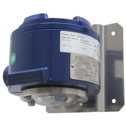
Діафрагмовий реле тиску, вибухозахисне виконання оболонки Ex d
Опис
Ці високоякісні механічні реле тиску розроблено спеціально для застосувань, де критично важлива безпека. Велика перевага механічних реле тиску полягає в тому, що для процесу перемикання не потрібна напруга живлення.
У виробництві перемикачі простежуються програмним забезпеченням системи забезпечення якості на кожному етапі, а потім виконуються 100 % випробування. Міцний корпус перемикача з алюмінієвого сплаву витримує жорсткі та корозійні умови експлуатації в процесній промисловості з робочими діапазонами до 600 bar. Реле тиску оснащене 1 або 2 мікроперемикачами, що дає змогу безпосередньо комутувати електричне навантаження до AC 250 V, 20 A.
Для нижчих значень комутованої потужності, наприклад для застосувань у PLC, доступні мікроперемикачі, заповнені аргоном, із позолоченими контактами.
Особливості
- Міцний корпус вимикача з алюмінієвого сплаву, IP66, NEMA 4X
- Діапазони налаштування від 16 mbar до 600 bar, а також всі інші еквівалентні діапазони вакууму або комбінованого тиску і вакууму
- 1 або 2 незалежні точки перемикання, висока потужність комутації до AC 250 В, 20 А
- Повторюваність точки перемикання < 1 %
Питання та відповіді
Який діапазон вимірювання реле тиску MA?
Діапазони налаштування — від 16 mbar до 600 bar, включно з еквівалентними вакуумними та комбінованими діапазонами «тиск/розрідження», наприклад −1 … 0 bar або −50 … +50 mbar.
Яка точність спрацювання?
Повторюваність точки перемикання < 1 %; точність згідно з IEC 61298-2:2008 становить ≤ 1 % від діапазону.
Які варіанти приєднання до процесу доступні?
¼ NPT (внутрішня різьба) як базовий варіант, а через адаптери — ½ NPT, G ¼ A, G ½ A; additionally фланці ASME B16.5 Class 150/300/600 та EN 1092-1 PN 10/40.
Для яких середовищ підходить цей прилад?
Для газоподібних і рідких, агресивних та високов'язких або забруднених середовищ; деталі, що контактують із середовищем, виготовляються зі Stainless steel 316/316L, Monel, Hastelloy C276, PTFE, FPM або NBR.
Який вибухозахист має модель MA?
Виконання Ex d: II 1/2 GD, Ex db IIC T6/T4 Gb та Ex tb IIIC T85/T135 Db, з сертифікаціями ATEX, IECEx, UKCA, EAC, Ex Ukraine, CCC, INMETRO, KCs та ECAS.
Чи придатне реле для систем протипожежного захисту?
Так, прилад має сертифікати відповідності EN 1854, EN 12952 та EN 12953 і кваліфікацію SIL 2 / SIL 3.
Чим модель MA відрізняється від сусідніх моделей серії?
Моделі MAB і MAG мають таке ж виконання II 1/2 GD, як MA, тоді як модель MAH виконана лише в рівні II 2 GD.
Яке електричне підключення передбачено?
Стандартно — ½ NPT (внутрішня різьба); додатково доступні ¾ NPT, Gk ½, Gk ¾, M20 x 1.5 (внутрішня різьба), кабельні вводи Ex d з нікельованої латуні або броньовані з AISI 304. ---
| Модель | MA |
| Підтип | Diaphragm pressure switch |
| Діапазон тиску | 0…40 bar · 0…0.016 bar · 0…0.2 bar · 0…0.4 bar · 0…1 bar · 0…1.2 bar · 0…2.5 bar · 0…6 bar · 0…10 bar · 0…16 bar · 0…25 bar · 4…40 bar · 10…100 bar · 10…250 bar · 20…400 bar · 30…600 bar · -0.1…0.1 bar · -0.5…0.5 bar · -1…0 bar · -1…1.5 bar · -1…5 bar · -1…9 bar · -1…15 bar · -0.2…0 bar · -0.4…0 bar · -12.5…12.5 mbar · -30…30 mbar · -50…50 mbar · 0…100 mbar |
| Клас точності | ≤ 1 % of span |
| Стандарт точності | IEC 61298-2:2008 |
| Рівень функціональної безпеки (SIL) | SIL 2-qualified, SIL 3-qualified |
| Технологічне приєднання | ¼ NPT, female thread½ NPT, female thread via adapter½ NPT, male thread via adapterG ¼, female thread via adapterG ½ A, male thread via adapterG ¼ A, male thread via adapterASME B16.5 FlangeEN 1092-1 FlangeG 1/2 BM20x1.51/2 NPTASME B16.5 Class 150/300/600EN 1092-1 PN 10/401/4 NPT, female thread1/2 NPT, female thread via adapter1/2 NPT, male thread via adapterG1/4, female thread via adapterG1/2 A, male thread via adapterG1/4 A, male thread via adapterASME B16.51EN 1092-1 |
| Темп. процесу | −60…+85 °C |
| Електр. приєднання | ½ NPT female (standard), ¾ NPT, Gk ½, Gk ¾, M20 x 1.5 female, Cable gland non-armoured, Ex d, nickel-plated brass, Cable gland armoured, Ex d, AISI 304 |
| Функція перемикання | 1 or 2 independent switch points, SPDT, DPDT |
| Перемикальні контакти | 2 |
| Матеріал корпусу | Aluminium alloy, copper-free, painted with acrylic paint |
| Матеріал змочуваних частин | Stainless steel 316, PTFE, Stainless steel 316L, Monel, Hastelloy C276, FPM, NBR |
| Матеріал ущільнення | FPM, NBR, PTFE, welded diaphragm |
| Темп. навколишнього середовища | −60…+85 °C |
| Ступінь захисту IP | IP66 |
| Вага | 3.1 kg |
| Сертифікати | NACE MR0175/ISO 15156NACE MR0103/ISO 17945EN 1854EN 12952EN 12953CERoHSEAC |
| Вибухозахист | II 1/2 GD (models MAB, MA, MAG)II 2 GD (model MAH)Ex db IIC T6/T4Gb, Ex tb IIIC T85/T135 Db (models MAB, MA, MAG)Gb, Ex tb IIIC T85/T135 Db (model MAH)ATEXIECExUKCAEACEx UkraineCCCINMETROKCsECASEx dEx db IIC T6/T4 Ga/GbEx tb IIIC T85/T135 DbEx db IIC T6/T4 Gb |
| Мови datasheet | EN |
| Basic information | |
|---|---|
| Version | Diaphragm pressure switch, flameproof enclosure Ex d |
| Special design feature | ■ For oxygen, oil- and grease-free ■ Per NACE 1) MR0175 / ISO 15156, use in H₂S-containing environments in oil and gas production ■ Per NACE 1) MR0103 / ISO 17945, metals resistant to sulphide stress cracking ■ Version compliant with EN 1854, pressure sensing devices for gas burners and gas burning appliances ■ Version compliant with EN 12952 and EN 12953, limiting devices in water- tube and shell boilers ■ Drying of wetted parts ■ Offshore version ■ Tropical version (suitable for environments with increased air humidity) ■ Version for ammonia applications ■ Geothermal version ■ Low-temperature version to -60 °C ■ Assembled as a diaphragm seal system ■ Additional protection from stainless steel 316L or Hastelloy for setting ranges 2.5 ... 25 bar |
| Contact version | →See table 'Contact version' |
| Function | ■ 1 x SPDT (single pole double throw) ■ 2 x SPDT (single pole double throw) ■ 1 x DPDT (double pole double throw) The DPDT function is realised with 2 simultaneously triggering SPDT microswitches, within 0.2 %of span. |
| Dead band | ■ 1 or 2 contacts with fixed dead band ■ 1 or 2 contacts with adjustable dead band ■ 1 contact with fixed dead band and 1 contact with adjustable dead band |
| Dielectric strength | Safety class I (IEC 61298-2: 2008) |
| Switch enclosure | |
| Design | Housing cover can be secured against unauthorised access with screw locking. Laser-engraved product label from stainless steel. |
| Material | Aluminium alloy, copper-free, painted with acrylic paint |
| Mounting 2) | ■ Direct mounting ■ Wall bracket from stainless steel AISI 304 ■ Mounting bracket for 2" pipe mounting from stainless steel AISI 304 |
| Contact version | Electrical rating (resistive load) | ||
|---|---|---|---|
| AC | DC | ||
| With fixed dead band | |||
| UN | 1 x SPDT, silver | 250 V, 15 A | 24 V, 2 A, 125 V, 0.5 A, 220 V, 0.25 A |
| US | 1 x SPDT, silver, hermetically sealed, argon gas filling 1) | 250 V, 15 A | 24 V, 2 A, 220 V, 0.5 A |
| UO | 1 x SPDT, gold-plated, hermetically sealed, argon gas filling 1) | 125 V, 1 A | 24 V, 0.5 A |
| UG | 1 x SPDT, gold-plated | 125 V, 1 A | 24 V, 0.5 A |
| DN | 2 x SPDT or 1 x DPDT, silver | 250 V, 15 A | 24 V, 2 A, 125 V, 0.5 A, 220 V, 0.25 A |
| DS | 2 x SPDT or 1 x DPDT, silver, hermetically sealed, argon gas filling 1) | 250 V, 15 A | 24 V, 2 A, 220 V, 0.5 A |
| DO | 2 x SPDT, or 1 x DPDT gold-plated, hermetically sealed, argon gas filling 1) | 125 V, 1 A | 24 V, 0.5 A |
| DG | 2 x SPDT or 1 x DPDT, gold-plated | 125 V, 1 A | 24 V, 0.5 A |
| Contact version | Electrical rating (resistive load) | ||
|---|---|---|---|
| AC | DC | ||
| With adjustable dead band | |||
| UR | 1 x SPDT, silver | 250 V, 20 A | 24 V, 2 A, 220 V, 0.5 A |
| RR 3) | 2 x SPDT or 1 x DPDT, silver | 250 V, 15 A | 24 V, 2 A, 220 V, 0.5 A |
| With fixed dead band and adjustable dead band | |||
| DR 3) | 2 x SPDT, silver (1 x UN + 1 x UR) | 250 V, 15 A | 24 V, 2 A, 220 V, 0.5 A |
| Sensor element | Model | Wetted parts | Permissible medium temperature 1) | ||
|---|---|---|---|---|---|
| Sensor element | Process connection | ||||
| Setting range 0 …16mbar to 0 …40bar | |||||
| XX 2) | Diaphragm element | MAB,MA | Stainless steel 316 3) | Stainless steel 316L | -30 ...+85 °C |
| TX | Diaphragm element | MAB,MA | Stainless steel 316 3) + PTFE 4) | Stainless steel 316L | -30 ...+85 °C |
| TT | Diaphragm element | MAB,MA | Stainless steel 316 3) + PTFE 4) | Stainless steel 316L + PTFE | -30 ...+85 °C |
| KK 2) | Diaphragm element | MAB,MA | Monel 5) | Monel | -30 ...+85 °C |
| KX 2) | Diaphragm element | MAB,MA | Monel 5) | Stainless steel 316L | -30 ...+85 °C |
| Setting range 4 …40bar to 30 …600 bar | |||||
| GXX 6) | Piston with welded diaphragm element | MAG | Hastelloy C276 | Stainless steel 316L | -40 ...+85 °C |
| HXX 7) | Piston with O-ring sealing from FPM | MAH | Stainless steel 316 | Stainless steel 316L | 0 ... 85 °C |
| Piston with O-ring sealing from NBR | MAH | Stainless steel 316 | Stainless steel 316L | -10 ...+85 °C |
Переглянути всі (20)
| Set point repeatability | ≤ 1 %of span of setting range |
|---|---|
| Dead band | →See table 'Setting range' |
| Standard | Variant 1 | Variant 2 | Dead band | |||||
|---|---|---|---|---|---|---|---|---|
| Setting range (= working range) | Proof pressure | Working range | Proof pressure | Working range | Proof pressure | 1 contact, fixed | 2 contacts, fixed | 1 contact, adjustable |
| in mbar | in bar | in mbar | in mbar | in mbar | ||||
| in bar | in bar | in bar | ||||||
| 0 ... 16 | 250 | 0 ... 8 | 10 | -1 ... 8 1) | 10 | ≤ 2.0 | ≤ 2.8 | - |
| 0…25 | 250 | 0 ... 8 | 10 | -1 ... 8 1) | 10 | ≤ 2.0 | ≤ 3 | 8 …18 |
| 0…40 | 300 | 0…8 | 10 | -1 ... 8 1) | 10 | ≤ 2.6 | ≤ 3.4 | 8…20 |
| 0 ... 60 | 300 | 0…8 | 10 | -1 ... 8 1) | 10 | ≤ 3.0 | ≤ 4.2 | 12…25 |
| 0 ... 100 | 600 | 0…8 | 10 | -1 ... 8 1) | 10 | ≤ 3.6 | ≤ 5 | 17…40 |
| Standard | Variant 1 | Variant 2 | Dead band | |||||
|---|---|---|---|---|---|---|---|---|
| Setting range (= working range) | Proof pressure | Working range | Proof pressure | Working range | Proof pressure | 1 contact, fixed | 2 contacts, fixed | 1 contact, adjustable |
| in mbar | in bar | in bar | in bar | in bar | in mbar | in mbar | in mbar | |
| -16 ... 0 | -21 | -1…0 1) | 0.25 | - | - | ≤ 2.0 | ≤ 2.8 | - |
| -25 ... 0 | -35 | -1…0 1) | 0.25 | - | - | ≤ 2.0 | ≤ 3 | 8…18 |
| -40 ... 0 | -55 | -1…0 1) | 0.30 | - | - | ≤ 2.6 | ≤ 3.4 | 8…20 |
| -60 ... 0 | -90 | -1…0 1) | 0.30 | - | - | ≤ 3.0 | ≤ 4.2 | 12…25 |
| -100 ... 0 | -150 | -1…0 1) | 0.40 | - | - | ≤ 3.6 | ≤ 5 | 17…40 |
| -12.5 ... +12.5 | -25 / 250 | - | - | - | - | ≤ 2.0 | ≤ 3 | 8…18 |
| -30 ... +30 | -60 / 250 | - | - | - | - | ≤ 3.0 | ≤ 4.2 | 12…25 |
| -50 ... +50 | -100 / 250 | - | - | - | - | ≤ 3.6 | ≤ 5 | 17…40 |
| Standard | Variant 1 | Variant 2 | Dead band | |||||
|---|---|---|---|---|---|---|---|---|
| Setting range (= working range) | Proof pressure | Working range | Proof pressure | Working range | Proof pressure | 1 contact, fixed | 2 contacts, fixed | 1 contact, adjustable |
| in bar | in bar | in bar | in bar | in bar | in mbar | in mbar | in mbar | |
| 0 ... 0.2 | 6 | 0…32 | 40 | -1…32 1) | 40 | ≤ 10 | ≤ 13 | 30…70 |
| 0 ... 0.4 | 10 | 0…32 | 40 | -1…32 1) | 40 | ≤ 15 | ≤ 20 | 40 ... 95 |
| -0.2 ... 0 | -0.3 | -1…0 1) | -1 | -1 ... 8 | 10 | ≤ 10 | ≤ 13 | 30…70 |
| -0.4 ... 0 | -0.6 | -1…0 1) | -1 | -1 ... 8 | 10 | ≤ 15 | ≤ 20 | 40…95 |
| -0.1 ... +0.1 | -0.2 / 1 | - | - | - | - | ≤ 10 | ≤ 13 | 30…70 |
| -0.5 ... 0.5 | -1 / 4 | - | - | - | - | ≤ 15 | ≤ 50 | 75 ... 170 |
| -1 ... 0 | -1 | -1…8 | 10 | - | - | ≤ 15 | ≤ 50 | 75 …170 |
| -1 ... 1.5 | 2 | -1…8 | 10 | - | - | ≤ 48 | ≤ 67 | 200 …500 |
| -1 ... 5 | 60 | -1…80 | 100 | - | - | ≤ 100 | ≤ 160 | 400 …1,000 |
| -1 ... 9 | 60 | -1…80 | 100 | - | - | ≤ 100 | ≤ 180 | 600 …1,400 |
| -1 ... 15 | 60 | -1…80 | 100 | - | - | ≤ 150 | ≤ 250 | 1,000 …2,400 |
| 0 ... 1 | 25 | 0…32 | 40 | -1…32 | 40 | ≤ 15 | ≤ 50 | 75 …170 |
| 0 ... 1.2 | 25 | 0…32 | 40 | -1…32 | 40 | ≤ 15 | ≤ 50 | 75 …170 |
| 0 ... 2.5 | 60 | 0…80 | 100 | -1…80 | 100 2) | ≤ 48 | ≤ 67 | 200 …500 |
| 0 ... 6 | 60 | -1…80 | 100 | - | - | ≤ 100 | ≤ 160 | 400 …1,000 |
| 0 ... 10 | 60 | -1…80 | 100 | - | - | ≤ 100 | ≤ 180 | 600 …1,400 |
| 0 ... 16 | 60 | -1…80 | 100 | - | - | ≤ 150 | ≤ 250 | 1,000 …2,400 |
| 0 ... 25 | 60 | -1…80 | 100 | - | - | ≤ 300 | ≤ 450 | 1,700 …4,000 |
| 0 ... 40 | 60 | - | - | - | - | ≤ 400 | ≤ 800 | 2,200 …5,800 |
| Standard | Dead band | |||
|---|---|---|---|---|
| Setting range (= working range) | Proof pressure | 1 contact, fixed | 2 contacts, fixed | 1 contact, adjustable 1) |
| in bar | in bar | in bar | in bar | |
| 4 ... 40 | 100 | ≤ 3 | ≤ 4 | 5…11to8…15 |
| 10 ... 100 | 200 | ≤ 4 | ≤ 6 | 10 …22to15…28 |
| 10 ... 250 | 400 | ≤ 10 | ≤ 13 | 15 …38to27…55 |
| 20 ... 400 | 600 | ≤ 10 | ≤ 25 | 35 …80to43…90 |
| 30 ... 600 | 700 | ≤ 20 | ≤ 25 | 45 ... 105 to 83 ... 155 |
| Process connection | |
|---|---|
| Standard | ■ ANSI/ASME B1.20.1 ■ DIN EN ISO 228 ■ ASME B16.5 1) ■ EN 1092-1 1) |
| Size | |
| ANSI/ASME B1.20.1 | ■ ¼NPT, female thread ■ ½NPT, female thread via adapter ■ ½NPT, male thread via adapter |
| DIN EN ISO 228 | ■ G¼, female thread via adapter ■ G½A,male thread via adapter ■ G¼A,male thread via adapter |
| ASME B16.5 1) | Flange variant 'S' :With fixed stud bolts and included nuts and washers |
| EN 1092-1 1) | Flange variant 'T' :With through-holes and extension pipe →See dimensions from page 9 |
| Material (wetted) | |
| Sensor element | Depending on the selected sensor element →See table 'Sensor element' |
| Process connection | |
| Sealing | PTFE, FPM, NBR, without sealing: welded diaphragm, depending on setting range and operating conditions. →See table 'Setting range' |
| Connection type | ■ ½NPTfemale (standard) ■ ¾NPT, Gk ½, Gk ¾, M20 x 1.5 female ■ Cable gland non-armoured, Ex d, nickel-plated brass ■ Cable gland non-armoured, Ex d, AISI 304 ■ Cable gland armoured, Ex d, nickel-plated brass ■ Cable gland armoured, Ex d, AISI 304 |
|---|---|
| Wire cross-section | Use 0.5 ... 1.5 mm² (20 ... 16 AWG) for internal terminal block (also suitable for cable lugs). For the grounding cable connection to the protective conductor use max. 4 mm² for the internal and external screw. |
| Pin assignment | Connection details are given on the product label of the instrument. Connection terminals and the ground terminal are appropriately marked. |
| Medium temperature range | Depending on sensor element and sealing →See table 'Sensor element' |
|---|---|
| Ambient temperature range | T6/T85°C T a -60 ...+60 |
| T4/T135°C T a -60 ...+85 | |
| Ingress protection of the complete instrument | IP66 per EN/IEC 60529 (NEMA 4X) |
| Weight | Approx. 3.1 kg for models MA, MAG,MAH Approx. 3.5 kg for model MAB |
| Logo | Description | Region |
|---|---|---|
| EU declaration of conformity Pressure equipment directive PED, annex 1, category IV, safety accessories, module B + D Low voltage directive RoHS directive ATEX directive 1) II 1/2 GD(models MAB, MA, MAG) | European Union | |
| IECEx 1) Ex db IIC T6/T4 2) Ga/Gb, Ex tb IIIC T85/T135 2) Db (models MAB, MA, MAG) Ex db IIC T6/T4 2) Gb, Ex tb IIIC T85/T135 2) Db (model MAH) | International |
| Logo | Description | Region |
|---|---|---|
| UKCA | United Kingdom | |
| Pressure equipment (safety) regulations | ||
| Electrical equipment designed for use within certain voltage limits in support of the electrical equipment (safety) regulations | ||
| Restriction of hazardous substances (RoHS) regulations | ||
| Equipment and protective systems intended for use in potentially explosive atmospheres regulations 1) | ||
| EAC Hazardous areas 1) | Eurasian Economic Community | |
| Ex Ukraine Hazardous areas 1) | Ukraine | |
| CCC Hazardous areas 1) | China | |
| INMETRO Hazardous areas 1 | Brazil | |
| KCs Hazardous areas 1) | South Korea | |
| - | ECAS Hazardous areas 1) | United Arab Emirates |
| Logo | Description |
|---|---|
| SIL3 IEC 61508 / IEC 61511 | SIL 3-capable (option) Functional safety per IEC 61508 Contains performance level calculation per ISO 13849-1 |
| Certificates | ■ 2.2 test report per EN 10204 (e.g. state-of-the-art manufacturing, indication accuracy) ■ 3.1 inspection certificate per EN 10204 (e.g. indication accuracy) |
|---|---|
| Recommended calibration interval | 1 year (dependent on conditions of use) |
| DN | Class | Dimensions in mm[in] | ||||
|---|---|---|---|---|---|---|
| D | b | a | P | L | ||
| ½" | 150 | 110 [43,31] | 25 [9,84] | 60,3 [23,74] | 4 x M14 | 51 [20,08] |
| 300 | 110 [43,31] | 25 [9,84] | 66,7 [26,26] | 4 x M14 | 51 [20,08] | |
| ¾" | 150 | 110 [43,31] | 25 [9,84] | 69,8 [27,48] | 4 x M14 | 51 [20,08] |
| 1" | 150 | 110 [43,31] | 25 [9,84] | 79,4 [31,26] | 4 x M14 | 51 [20,08] |
| 300 | 150 [59,06] | 25 [9,84] | 88,9 [35] | 4 x M16 | 54 [21,26] | |
| 1 ½" | 150 | 150 [59,06] | 25 [9,84] | 98,4 [38,74] | 4 x M14 | 51 [20,08] |
| 300 | 150 [59,06] | 25 [9,84] | 114,3 [45] | 4 x M20 | 60 [23,62] | |
| 2" | 150 | 150 [59,06] | 25 [9,84] | 120,6 [47,48] | 4 x M16 | 54 [21,26] |
| 300 | 165 [64,96] | 22 [8,66] | 127 [50] | 8 x M16 | 54 [21,26] |
| DN | PN | Dimensions in mm[in] | ||||
|---|---|---|---|---|---|---|
| D | b | a | P | L | ||
| 15 | 10/40 | 110 [43,31] | 25 [9,84] | 65 [25,59] | 4 x M12 | 48 [18,9] |
| 20 | 10/40 | 110 [43,31] | 25 [9,84] | 75 [29,53] | 4 x M12 | 48 [18,9] |
| 25 | 10/40 | 110 [43,31] | 25 [9,84] | 85 [33,46] | 4 x M12 | 48 [18,9] |
| 40 | 10/40 | 150 [59,06] | 25 [9,84] | 110 [43,31] | 4 x M16 | 54 [21,26] |
| DN | Class | Dimensions in mm[in] | |||
|---|---|---|---|---|---|
| B | D | ||||
| FF | RF | RJ | |||
| ½" | 300 | 12,6 [4,96] | 14,2 [5,59] | - | 12 [4,72] |
| 600 | - | 20,6 [8,11] | 19,8 [7,8] | 12 [4,72] | |
| ¾" | 150 | 11,2 [4,41] | 12,8 [5,04] | - | 12 [4,72] |
| 300 | 14,3 [5,63] | 15,9 [6,26] | - | 11 [4,33] | |
| 600 | - | 22,1 [8,7] | 22,1 [8,7] | 11 [4,33] | |
| 1" | 150 | 12,6 [4,96] | 14,2 [5,59] | - | 11 [4,33] |
| 300 | 15,9 [6,26] | 17,5 [6,89] | - | 11 [4,33] | |
| 600 | - | 23,9 [9,41] | 23,9 [9,41] | 11 [4,33] | |
| 1 ½" | 150 | 15,9 [6,26] | 17,5 [6,89] | - | 26,7 [10,51] |
| 300 | 19,1 [7,52] | 20,7 [8,15] | - | 26,7 [10,51] | |
| 600 | - | 28,7 [11,3] | 28,7 [11,3] | 26,7 [10,51] | |
| 2" | 150 | 17,5 [6,89] | 19,1 [7,52] | - | 26,7 [10,51] |
| 300 | 20,7 [8,15] | 22,3 [8,78] | - | 26,7 [10,51] | |
| 600 | - | 31,7 [12,48] | 32,2 [12,68] | 26,7 [10,51] |
| DN | PN | Dimensions in mm[in] | ||
|---|---|---|---|---|
| B | D | |||
| Form A | Form B1 | |||
| 20 | 10/40 | 18 [7,09] | 18 [7,09] | 16 [6,3] |
| 25 | 10/40 | 18 [7,09] | 18 [7,09] | 25 [9,84] |
| 40 | 10/40 | - | 18 [7,09] | 25 [9,84] |
Не знайшли відповіді у документації? Інженер відповість впродовж робочого дня.
Запитати інженера →