
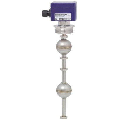
Поплавковый выключатель
Описание
Поплавок с постоянным магнитом надёжно перемещается вместе с уровнем жидкости по направляющей трубе. Внутри направляющей трубы установлен геркон (контакт для инертного газа), который подаётся под напряжение через немагнитные стенки поплавка и направляющей трубы при приближении магнита поплавка. За счёт применения магнита и герконового контакта операция переключения выполняется бесконтактно, не подвержена износу и не требует электропитания. Контакты являются потенциально-развязанными. Также доступны поплавковые выключатели с несколькими точками переключения.
Функции переключения всегда относятся к повышающемуся уровню жидкости: нормально разомкнутый, нормально замкнутый или переключающий контакт.
для получения дальнейших допусков см. стр. 3
Рис. слева: вариант из нержавеющей стали, монтажная резьба, модель FLS-S Рис. справа: вариант из пластика, фланцевое соединение, модель FLS-P
За счёт применения поплавка максимум на 2 точки переключения можно обеспечить бистабильное поведение переключателя, то есть состояние переключения сохраняется также тогда, когда уровень заполнения продолжает подниматься выше или опускаться ниже точки переключения.
Поплавковый выключатель прост в монтаже и не требует технического обслуживания, поэтому затраты на монтаж, пусконаладку и эксплуатацию невысоки.
Особенности
- Широкая область применения благодаря простому и проверенному принципу работы
- Для тяжёлых условий эксплуатации, длительный срок службы
- Рабочие параметры: Рабочая температура: T = -50 ... +350 °C Рабочее давление: P = Вакуум до 40 bar Предельная плотность: ρ ≥ 300 kg/m 3
- Рабочая температура: T = -50 ... +350 °C
- Рабочее давление: P = Вакуум до 40 bar
- Предел плотности: ρ ≥ 300 kg/m 3
- Большой выбор различных электрических и процессных присоединений и материалов
- Взрывозащищённые исполнения
Вопросы и ответы
Какой диапазон уровней измеряет поплавковый выключатель FLS?
От 0 до 6000 мм в зависимости от длины направляющей трубы.
В каком диапазоне температур и давлений работает прибор?
Рабочая температура от -50 до +350 °C, рабочее давление — от вакуума до 40 бар; минимальная плотность среды ρ ≥ 300 кг/м³.
Какие присоединения к процессу доступны?
Резьбовые G 1 1/2" и G 2", фланцевые по DIN DN 50 … DN 200 и ANSI 2" … 8".
Для каких сред подходит выключатель?
Практически для всех жидких сред с плотностью не ниже 300 кг/м³; материалы смачиваемых частей включают нержавеющие стали 1.4571 (316Ti), 1.4404 (316L), 1.4435 (316L), пластик (PP, PA), латунь, Titanium и Hastelloy.
Какая степень защиты корпуса?
IP66/IP68; корпус подключения выполнен из алюминия размером 64 x 58 x 34 мм с одним контактом.
Есть ли взрывозащищённые исполнения?
Да: версии Ex i (Ex ia IIC T6 … T1 Ga/Gb) и Ex d (Ex d IIC T6 Gb) для газовых и пылевых сред.
Чем FLS-S отличается от FLS-P?
Модель FLS-S выполнена из нержавеющей стали с монтажной резьбой, модель FLS-P — из пластика с фланцевым соединением; обе работают по одному магнито-герконовому принципу.
Какой тип выходного сигнала обеспечивает выключатель?
Нормально разомкнутый (NO), нормально замкнутый (NC) или переключающий контакт (SPDT); питание — безопасное сверхнизкое напряжение, контакты потенциально развязаны.
| Модель | FLS-S |
| Серия | FLS |
| Подтип | float |
| Диапазон уровня | 0…6000 mm |
| Технологическое присоединение | G 1 1/2"G 2"DIN DN 50 ... DN 200ANSI 2" ... 8" |
| Темп. процесса | −50…+350 °C |
| Макс. давление процесса | 40 bar |
| Технология измерения | float |
| Выходной сигнал | NO · NC · SPDT |
| Питание | safety extra-low voltage |
| Электр. соединение | Connection housing Aluminium 64 x 58 x 34 mm, with 1 contact |
| Материал смачиваемых частей | 1.4571 (316Ti), 1.4404 (316L), 1.4435 (316L), PP, PA, Ms, Buna, Titanium, Hastelloy |
| Темп. окружающей среды | −50…+350 °C |
| Степень защиты IP | IP66/IP68 |
| Сертификаты | CERoHSEACDNV GLABSBureau VeritasLloyd’s RegisterDIBt |
| Взрывозащита | Ex i II 1/2G Ex ia IIC T6 ... T1 Ga/Gb II 2D Ex ib IIIC T80°C ... T230°C DbEx d II 2G Ex d IIC T6 Gb II 2D Ex tb IIIC T80 °C Db |
| Языки datasheet | EN, DE |
| Model | Description | Materials | ||||||||
|---|---|---|---|---|---|---|---|---|---|---|
| Stainless steel | Titanium 3.7035 (grade 2) | PVC / PP / PVDF | ||||||||
| 1.4571 (316Ti) | 1.4404 (316L) | 1.4435 (316L) | 1.4571 (316Ti) / PP | 1.4571 (316Ti) / PA | 1.4571 (316Ti) / Ms | 1.4571 (316Ti) / Buna | ||||
| FLS-SE | Standard version, cable connection, safety extra-low voltage | x | x | x | x | x | x | x | x | - |
| FLS-SF | Standard version, cable connection, low voltage | x | x | x | x | x | x | x | x | - |
| FLS-SA | Standard version, connection housing or connector, low voltage | x | x | x | x | x | x | x | x | - |
| FLS-SB | Standard version, connection housing or connector, safety extra-low voltage | x | x | x | x | x | x | x | x | - |
| FLS-SBI (60) | Intrinsically safe, Ex i | x | x | - | - | - | - | - | x | - |
| FLS-SAD FLS-SBD (AL-ADF) | Flameproof enclosure, Ex d | x | x | - | - | - | - | - | - | - |
| FLS-ME | Miniature design, cable connection, safety extra-low voltage | x | x | - | x | - | - | x | - | - |
| FLS-MB | Miniature design, connection housing or connector, safety extra-low voltage | x | x | - | x | - | - | x | - | - |
| FLS-PF | Plastic version, cable connection, low voltage | - | - | - | - | - | - | - | - | x |
| FLS-PA | Plastic version, connection housing or connector, low voltage | - | - | - | - | - | - | - | - | x |
| FLS-HE | Pharmaceutical version, cable connection, safety extra-low voltage | - | x | x | - | - | - | - | - | - |
| FLS-HA | Pharmaceutical version, connection housing, low voltage | - | x | x | - | - | - | - | - | - |
| FLS-HA3 | Sterile version (3-A), connection housing, low voltage | - | x | x | - | - | - | - | - | - |
| FLS-F | Food version, connection housing, low voltage | - | x | x | - | - | - | - | - | - |
| Models FLS-SE, FLS-SF, FLS-HE | -30 ...+180 °C |
|---|---|
| Models FLS-SA, FLS-SB | -50 ...+350 °C |
| Model FLS-SxI (60) | -50 ...+180 °C |
| Models FLS-SxD (AL-ADF) | -10 ...+120 °C |
| Model FLS-M | -10 ...+100 °C |
| Model FLS-P | -10 ...+100 °C |
| Models FLS-HA, FLS-HA3 | -40 ...+200 °C |
| Model FLS-F | -30 ...+180 °C |
| Logo | Description | Country |
|---|---|---|
| EU declaration of conformity ■ Low voltage directive ■ RoHS directive | European Union | |
| EAC ■ EMCdirective ■ Low voltage directive ■ Hazardous areas | Eurasian Economic Community | |
| DNV GL ■ Ships, shipbuilding (e.g. offshore) ■ Hazardous areas | International | |
| ABS ■ Ships, shipbuilding (e.g. offshore) ■ Hazardous areas | International | |
| Bureau Veritas Ships, shipbuilding | International | |
| APPROVED TYPE | Lloyd's Register Ships, shipbuilding (e.g. offshore) | International |
| - | DIBt Safety (e.g. electr. safety, overpressure, ...) Overflow control per German Water Resources Act (WHG) § 19 | Germany |
| Logo | Description | Country |
|---|---|---|
| EU declaration of conformity ■ Low voltage directive ■ RoHS directive | European Union | |
| EAC EMCdirective Low voltage directive | Eurasian Economic Community |
Смотреть все (20)
| Model FLS-SA, low voltage | Model FLS-SB, safety extra-low voltage | |
|---|---|---|
| Electrical connection | ■ Connection housing Aluminium 64 x 58 x 34 mm, with 1 contact Aluminium 80 x 75 x 57 mm, 2 or more contacts Option: Polypropylene, polyester, stainless steel ■ Coupler connector DIN EN 175301-803 (previously DIN 43650, 4-pin) M12 (4- or 8-pin) | |
| Process connection | ■ Mounting thread downwards G11/2" G2" Others on request ■ Mounting flange DIN DN 50 ...DN 200, PN 6 ...PN 100 DIN EN 1092-1 DN 50 ...DN 200, PN 6 ...PN 100 ANSI 2' ... 8', Class 150 ...600 | |
| Guide tube diameter | 12mm/14mm/18mm | |
| Guide tube length L | ≤ 3,000 mmfor guide tube diameter 12 or14mm ≤ 6,000 mmfor guide tube diameter18mm | |
| Float | Material: Stainless steel 1.4571 (option: Buna (NBR), titanium) Float diameter: 44 ...120mm Float selection depending on guide tube diameter and process conditions (see page 16, 17, 18) | |
| Temperature range | Observe the temperature range of the float and the connection housing Temperature range of the connector on request | |
| Standard version | -30 ...+180 °C | |
| High-temperature version | -30 ...+250 °C | |
| Low-temperature version | -50 ...+180 °C | |
| Maximum temperature version | -30 ...+350 °C | |
| Switching function | Alternatively normally open (NO), normally closed (NC) or change-over (SPDT) contact - on rising level | |
| Max. number of contacts | 6 x NOor NC, or 4 x SPDT | |
| Switch position | Dimensions L1, L2, L3 ... (from sealing face, starting from top) | |
| Distance between switch points | Minimum 20 mm(depending on the selection of the float and the contacts) | |
| Switching power | ||
| Normally open, normally closed | AC ≤ 230 V; 100 VA; 1 A DC ≤ 230 V; 50 W;0.5 A | AC < 50 V; 100 VA; 1 A DC < 75 V; 50 W;0.5 A |
| Change-over | AC ≤ 230 V; 40 VA; 1 A DC ≤ 230 V; 20 W;0.5 A | AC < 50 V; 40 VA; 1 A DC < 75 V; 20 W;0.5 A |
| Mounting position | Vertical ±30° |
| Model FLS-SF, low voltage | Model FLS-SE, safety extra-low voltage | |
|---|---|---|
| Electrical connection | Connection cable ■ PVC ■ Silicone ■ PUR | |
| Process connection | Mounting thread upwards:G⅜"or G½" Others on request | |
| Guide tube diameter | 12mm/14mm/18mm | |
| Guide tube length L | ≤ 3,000 mmfor guide tube diameter 12 or14mm ≤ 6,000 mmfor guide tube diameter18mm | |
| Float | Material: Stainless steel 1.4571 (option: Buna (NBR), titanium) Float diameter: 44 ...120mm Float selection depending on guide tube diameter and process conditions (see page 16, 17, 18) | |
| Temperature range | ||
| PVC/PUR cable | -10 ...+80 °C | |
| Silicone cable | -30 ...+180 °C | |
| Observe the temperature range of the float | ||
| Switching function | Alternatively normally open (NO), normally closed (NC) or change-over (SPDT) contact - on rising level | |
| Max. number of contacts | 6 x NOor NC, or 4 x SPDT for PVC and PUR cable 5 x NOor NC, or 3 x SPDT for silicone cable | |
| Switch position | Dimensions L1, L2, L3 ... (from sealing face, starting from top) | |
| Distance between switch points | Minimum 20 mm(depending on the selection of the float and the contacts) | |
| Switching power | ||
| Normally open, normally closed | AC ≤ 230 V; 100 VA; 1 A DC ≤ 230 V; 50 W;0.5 A | AC < 50 V; 100 VA; 1 A DC < 75 V; 50 W;0.5 A |
| Change-over | AC ≤ 230 V; 40 VA; 1 A DC ≤ 230 V; 20 W;0.5 A | AC < 50 V; 40 VA; 1 A DC < 75 V; 20 W;0.5 A |
| Mounting position | Vertical ±30° |
| Model FLS-SBI | ||||||
|---|---|---|---|---|---|---|
| Electrical connection | Connection housing: Aluminium | |||||
| Option: Polyester, stainless steel | ||||||
| Process connection | ■ Mounting thread downwards G11/2" or G2" ■ Mounting flange - DIN DN 50 ...DN 200, PN 6 ...PN 100 - DIN EN 1092 DN 50 ...DN 200, PN 6 ...PN 100 - ANSI 2" ... 8", Class 150 ...600 Others on request | |||||
| Guide tube diameter | 12mm/14mm/18mm | |||||
| Guide tube length L | ≤ 3,000 mmfor guide tube diameter 12 or14mm ≤ 6,000 mmfor guide tube diameter18mm | |||||
| Float | Material: Stainless steel 1.4571 (option: Buna (NBR), titanium) Float diameter: 44 ...120mm Float selection depending on guide tube diameter and process conditions (see page 16, 17, 18) | |||||
| Temperature class | T1 | T2 | T3 | T4 | T5 | T6 |
| Process temperature | Max. 180 °C | Max. 180 °C | Max. 180 °C | Max. 130 °C | Max. 95 °C | Max. 80 °C |
| Ambient temperature at connection housing (T a ) | Max. 80 °C | Max. 80 °C | Max. 80 °C | Max. 80 °C | Max. 65 °C | Max. 50 °C |
| →Versions with optional circuits (e g. resistor connection, NAMURor temperature contacts), as well as surface temperature (EPL Db) at dust protection see operating instructions | ||||||
| Switching function | Alternatively normally open (NO), normally closed (NC) or change-over (SPDT) contact - on rising level | |||||
| Max. number of contacts | 6 x NOor NC, or 4 x SPDT for guide tube diameter 12, 14 or18mm | |||||
| Switch position | Dimensions L1, L2, L3 ... (from sealing face, starting from top) | |||||
| Distance between switch points | Minimum 20 mm(depending on the selection of the float and the contacts) | |||||
| Switching power | Only for connection to a certified intrinsically safe circuit with max. | |||||
| U i = 36V | I i = 100mA | C i = 0 nF | L i = 0 μH | |||
| Mounting position | Vertical ±30° |
| Model FLS-SAD | Model FLS-SBD | |
|---|---|---|
| Electrical connection | Connection housing: Aluminium Option: Stainless steel | |
| Process connection | ■ Mounting thread downwards G11/2" or G2" ■ Mounting flange DIN DN 50 ...DN 350, PN 6 ...PN 40 ANSI 2" ... 14", Class 150 ...300 | |
| Guide tube diameter | 12mm/14mm | |
| Guide tube length L | ≤ 4,000 mmfor guide tube diameter12mm ≤ 6,000 mmfor guide tube diameter14mm | |
| Float | Material: Stainless steel 1.4571 Float diameter: 44 ...80mm Float selection depending on guide tube diameter and process conditions (see page 16, 17, 18) | |
| Temperature range (process temperature) | T4 T5 T6 ≤ 120 °C ≤ 95 °C ≤ 80 °C | |
| Switching function | Change-over SPDT - on rising level | |
| Max. number of contacts | 4 x SPDT | |
| Switch position | Dimensions L1, L2, L3 ... (from sealing face, starting from top) | |
| Distance between switch points | Minimum 20 mm(depending on the selection of the float and the contacts) | |
| Switching power | AC ≤ 230 V; 100 VA; 1.5 A DC ≤ 230 V; 60 W;1.5 A | ■ With series resistance AC < 50V;40VA;150mA DC < 75V;20W;150mA ■ With NAMUR circuit per DIN EN 60947-5-6 AC < 50V;40VA;7mA DC < 75V;20W;7mA |
| Mounting position | Vertical ±30° |
| Model FLS-ME | Model FLS-MB | |||
|---|---|---|---|---|
| Electrical connection | Connection cable ■ PVC ■ Silicone ■ PUR | ■ Connection housing: Aluminium 64 x 58x34mm ■ Coupler connector DIN EN 175301-803 (previously DIN 43650, 4-pin) M12 (4- or 8-pin) | ||
| Process connection | Mounting thread upwards G1/8" Others on request | Mounting thread downwards G3/4" or G1" Others on request | ||
| Guide tube diameter | 8mm | |||
| Guide tube length L | ≤ 500mm | |||
| Float | Material: Stainless steel 1.4571 (option: Buna (NBR), titanium, PP) Float diameter from 20 ...35mm Float selection depending on guide tube diameter and process conditions (see page 16, 17, 18) | |||
| Temperature range | PVC/PUR cable | -10 ...+80 °C | Buna (NBR), PP | -10 ...+80 °C |
| Silicone cable | -30 ...+150 °C | Stainless steel, titanium | -30 ...+150 °C | |
| Observe the permissible temperature range of the float. | ||||
| Switching function | Alternatively normally open (NO), normally closed (NC) or change-over (SPDT) contact - on rising level | |||
| Max. number of contacts | 3 x NOor NC, or 2 x SPDT | |||
| Switch position | Dimensions L1, L2, L3 ... (from sealing face, starting from top) | |||
| Distance between switch points | Minimum 20 mm(depending on the selection of the float and the contacts) | |||
| Switching power | ||||
| Normally open, normally closed | AC < 50 V; 10 VA; 0.5 A | DC < 75 V; 5 W;0.25 A | ||
| Change-over | AC < 50 V; 5 VA; 0.25 A | DC < 75 V; 2.5 W;0.15 A | ||
| Versions FLS-MF, FLS-MA 1) | AC ≤ 230 V; 10 VA; 0.5 A | DC ≤ 230 V; 5 W;0.25 A | ||
| Mounting position | Vertical ±30° |
| Model FLS-PF | Model FLS-PA | |
|---|---|---|
| Electrical connection | Connection cable ■ PVC ■ PUR | ■ Connection housing Polypropylene 80 x 82x55mm Polyester 80 x 75x55mm ■ Coupler connector DIN EN 175301-803 (previously DIN 43650, 4-pin) M12 (4- or 8-pin) |
| Process connection | Mounting thread upwards G3/8" others on request | Mounting thread downwards ■ G11/2" ■ G2" Flange ■ DIN DN50 ...DN200, PN 6 ...PN 100 ■ DIN EN 1092-1 DN50 ...DN200, PN6...PN 100 ■ ANSI 2" ... 8", Class 150 ...600 |
| Guide tube diameter | 12mm/16mm/20mm | |
| Guide tube length L | ≤ 500 mmfor guide tube diameter12mm ≤ 3,000 mmfor guide tube diameter16mm ≤ 5,000 mmfor guide tube diameter20mm | |
| Float | Material: PVC, PP or PVDF Float diameter from 44 ...80mm Float selection depending on guide tube diameter and process conditions (see page 16, 17, 18) | |
| Temperature range | For float material PVC 0 ... 60 °C For float material PP -10 ...+80 °C For float material PVDF -10 ...+100 °C | |
| Switching function | Alternatively normally open (NO), normally closed (NC) or change-over (SPDT) contact - on rising level | |
| Max. number of contacts | 6 x NOor NC, or 4 x SPDT | |
| Switch position | Dimensions L1, L2, L3 ... (from sealing face, starting from top) | |
| Distance between switch points | Minimum 20 mm(depending on the selection of the float and the contacts) | |
| Switching power | ||
| Normally open, normally closed | AC ≤ 230 V; 100 VA; 1 A | DC ≤ 230 V; 50 W;0.5 A |
| Change-over | AC ≤ 230V ; 40 VA; 1 A | DC ≤ 230 V; 20 W;0.5 A |
| Mounting position | Vertical ±30° |
| Model FLS-HA | Model FLS-HE | ||
|---|---|---|---|
| Electrical connection | Connection housing: ■ Stainless steel | Connection cable ■ PVC ■ Silicone ■ PUR | |
| Process connection | ■ Mounting thread upwards G3/8" ■ Mounting flange per DIN or ANSI ■ Threaded connection per DIN 11851 ■ Clamp pipe connection per DIN 32676 ■ Ingold connection Others on request | ||
| Guide tube diameter | 17.2 mm(stainless steel 1.4435 or 1.4539, surface ground and polished) | ||
| Guide tube length L | ≤ 5,000mm | ||
| Float | Material: Stainless steel 1.4435 or 1.4539 Float diameter from 44 ...120mm Float selection depending on guide tube diameter and process conditions (see page 16, 17, 18) | ||
| Temperature range | PVC/PUR cable | -10 ...+80 °C | |
| Silicone cable | -30 ...+150 °C | ||
| Switching function | Alternatively normally open (NO), normally closed (NC) or change-over (SPDT) contact - on rising level | ||
| Max. number of contacts | 6 x NOor NC, or 4 x SPDT | 6 x NOor NC, or 4 x SPDT for PVC and PUR cable 3 x NOor NC, or 2 x SPDT for silicone cable | |
| Switch position | Dimensions L1, L2, L3 ... (from sealing face, starting from top) | ||
| Distance between switch points | Minimum 20 mm(depending on the selection of the float and the contacts) | ||
| Switching power | |||
| Normally open, normally closed | AC ≤ 230 V; 100 VA; 1 A DC ≤ 230 V; 50 W;0.5 A | AC < 50 V; 100 VA; 1 A DC < 50 V; 50 W;0.5 A | |
| Change-over | AC ≤ 230V ; 40 VA; 1 A DC ≤ 230 V; 20 W;0.5 A | AC < 50 V; 40 VA; 1 A DC < 50 V; 20 W;0.5 A | |
| Mounting position | Vertical ±30° |
| Model FLS-HA3 with separate float bracket | Model FLS-HA3 with welded pipe connection | |
|---|---|---|
| Electrical connection | Connection housing: stainless steel | |
| Process connection | ■ Clamp pipe connection ISO 2852, DN 32 …DN100or 1.5" …4" ■ Clamp pipe connection DIN 32676, DN 32 …DN100or 1.5" …4" ■ Aseptic mounting thread downwards DIN 11864-1, DN 32 ...DN 100 or 1.5" ... 4" ■ Aseptic liner DIN 11864-1, DN 32 ...DN 100 or 1.5" ... 4" ■ Aseptic flange connection DIN 11864-2 (DN 32 ...DN 50 or 1.5" ... 2" ■ Aseptic clamp connection DIN 11864-3, DN 32 ...DN 100 or 1.5" ... 4" ■ VARIVENT ® (form F,N and G) ■ BioConnect ® threaded connection, DN 32 …DN100or 1,5" …2" ■ BioConnect ® flange connection, DN 32 …DN100or 1.5" …2" ■ BioConnect ® clamp connection, DN 32 …DN100or 1.5" …4" | |
| Guide tube diameter | 12 mm/ 14 mm/ 17.2 mm(stainless steel 1.4435 or 1.4539, surface ground or polished, R a < 0.8 µm) | |
| Guide tube length L | ≤ 5,000mm | |
| Float | Material: Stainless steel 1.4435 or 1.4539 Float diameter:50 ...80mm Float selection depending on guide tube diameter and process conditions (see page 16, 17, 18) | |
| Temperature range | ||
| Process temperature | -40 ...+200 °C | |
| Ambient temperature | -40 ...+85 °C | |
| Switching function | Alternatively normally open (NO), normally closed (NC) or change-over (SPDT) contact - on rising level | |
| Max. number of contacts | 3 x NOor NC, or 3 x SPDT | |
| Switch position | Dimensions L1, L2, L3 ... (from sealing face, starting from top) | |
| Distance between switch points | Minimum 50 mm(depending on the selection of the float and the contacts) | |
| Switching power | ||
| Normally open, normally closed | AC ≤ 230 V; 100 VA; 1 A DC ≤ 230 V; 50 W;0.5 A | |
| Change-over | AC ≤ 230V ; 40 VA; 1 A DC ≤ 230 V; 20 W;0.5 A | |
| Mounting position | Vertical ±30° |
| Model | Angled version | Adjustable guide tube | ECTFE coating | Special flange from polyamide or brass | Food version |
|---|---|---|---|---|---|
| FLS-SE | x | x | - | - | x |
| FLS-SF | x | x | - | - | x |
| FLS-SA | x | x | x | x | x |
| FLS-SB | x | x | x | x | x |
| FLS-SBI (60) | x | - | - | - | - |
| FLS-ME | x | x | - | - | - |
| FLS-MB | x | x | - | - | - |
| FLS-PF | x | - | - | - | - |
| FLS-PA | x | - | - | - | - |
| Threaded pipe connection | Clamp pipe connection | |
|---|---|---|
| Electrical connection | Connection housing: ■ Aluminium 64 x 58 x 34 mm, with 1 contact ■ Aluminium 80 x 75 x 57 mm, 2 or more contacts Option: Polypropylene, polyester, stainless steel | |
| Process connection | Threaded pipe connection per DIN 11851, downwards DN 50 ...DN 150 others on request | Clamp pipe connection per DIN 32676, DN 25 …DN100or 1" …4" others on request |
| Guide tube diameter | 12mm/14mm/18mm | |
| Guide tube length L | ≤ 3,000 mmfor guide tube diameter 12 or14mm ≤ 6,000 mmfor guide tube diameter18mm | |
| Float | Material stainless steel 1.4435 or 1.4404, option electropolished Float diameter from 44 ...80mm Float selection depending on guide tube diameter and process conditions (see page 16, 17, 18) | |
| Temperature range (process temperature) | -30 ...+180 °C | |
| Switching function | Alternatively normally open (NO), normally closed (NC) or change-over (SPDT) contact - on rising level | |
| Max. number of contacts | 3 x NOor NC, or 3 x SPDT | |
| Switch position | Dimensions L1, L2, L3 ... (from sealing face, starting from | top) |
| Distance between switch points | Minimum 50 mm(depending on the selection of the float and the contacts) | |
| Switching power | ||
| Normally open, normally closed | AC ≤ 230 V; 100 VA; 1 A DC ≤ 230 V; 50 W;0.5 A | |
| Change-over | AC ≤ 230V ; 40 VA; 1 A DC ≤ 230 V; 20 W;0.5 A | |
| Mounting position | Vertical ±30° |
| Material | Version | Suits guide tube Ø inmm | Ø A inmm | B inmm | Ø C inmm | Max. operating pressure in bar | Max. operating temp. in °C | Limit density 85% in kg/m 3 | Order no. |
|---|---|---|---|---|---|---|---|---|---|
| Stainless steel 1.4571 | V29A | 8 | 29 | 28 | 9 | 25 | 100 | 920 | 027355 |
| V52A | 12 | 52 | 52 | 15 | 40 | 250 | 700 | 005462 | |
| V52T | 12 | 52 | 52 | 15 | 40 | 350 | 730 | 033560 | |
| V62A | 12 | 62 | 61 | 15 | 32 | 250 | 590 | 005473 | |
| V83A | 12 | 83 | 81 | 15 | 25 | 250 | 430 | 005485 | |
| V80A | 18 | 80 | 76 | 23 | 25 | 250 | 680 | 005478 | |
| V98A | 18 | 98 | 96 | 23 | 25 | 250 | 600 | 005489 | |
| V105A | 18 | 105 | 103 | 23 | 25 | 250 | 530 | 020652 | |
| V120A | 18 | 120 | 117 | 23 | 25 | 250 | 390 | 021721 | |
| Titanium 3.7035 | T29A | 8 | 29 | 28 | 9 | 30 | 100 | 700 | 005522 |
| T52A | 12 | 52 | 52 | 15 | 25 | 300 | 570 | 005525 | |
| T62A | 12 | 62 | 62 | 15 | 25 | 300 | 505 | 005536 | |
| T83A | 12 | 83 | 81 | 15 | 25 | 300 | 350 | 005544 | |
| T80A | 18 | 80 | 76 | 23 | 25 | 300 | 665 | 112263 | |
| T98A | 18 | 98 | 96 | 23 | 25 | 300 | 495 | - | |
| T105A | 18 | 105 | 103 | 23 | 25 | 300 | 370 | - | |
| T120A | 18 | 120 | 117 | 23 | 25 | 300 | 330 | - | |
| Stainless steel 1.4571 ECTFE coated | VEC53A | 12 | 53 | 53 | 14 | 25 | Depending on medium | 850 | 111415 |
| VEC63A | 12 | 63 | 62 | 14 | 25 | Depending on medium | 590 | - | |
| VEC84A | 12 | 84 | 82 | 14 | 25 | Depending on medium | 400 | - | |
| VEC81A | 18 | 81 | 77 | 22 | 25 | Depending on medium | 720 | - | |
| VEC99A | 18 | 99 | 97 | 22 | 25 | Depending on medium | 675 | - | |
| VEC106A | 18 | 106 | 104 | 22 | 25 | Depending on medium | 630 | - | |
| VEC121A | 18 | 121 | 118 | 22 | 25 | Depending on medium | 460 | - |
| Material | Version | Suits guide tube Ø inmm | Ø A inmm | B inmm | Ø C inmm | Max. operating pressure in bar | Max. operating temp. in °C | Limit density 85% in kg/m 3 | Order no. |
|---|---|---|---|---|---|---|---|---|---|
| Stainless steel 1.4571 | V27A | 8 | 27 | 31 | 10 | 16 | 100 | 787 | 009679 |
| V29A/40 | 12 | 29 | 40 | 13,4 | 10 | 180 | 720 | 030352 | |
| V44A | 12 | 44 | 52 | 15 | 16 | 300 | 720 | 009681 | |
| V44T | 12 | 44 | 52 | 15 | 16 | 350 | 780 | 033561 | |
| Titanium 3.7035 | T44A | 12 | 44 | 52 | 15 | 16 | 300 | 720 | 009744 |
| Buna (NBR) | B20A | 8 | 20 | 20 | 9 | 3 | 80 | 940 | 009719 |
| B23A | 8 | 23 | 25 | 9 | 3 | 80 | 800 | 009721 | |
| B25A | 8 | 25 | 14 | 9 | 3 | 80 | 790 | 009720 | |
| B30A | 8 | 30 | 45 | 13 | 3 | 80 | 680 | 034047 | |
| B40A | 12 | 40 | 30 | 15 | 3 | 80 | 580 | 009728 | |
| B40A/120 | 12 | 40 | 120 | 15 | 3 | 80 | 410 | 14377687 | |
| B50A | 18 | 50 | 45 | 19 | 3 | 80 | 500 | 009725 | |
| PVC | P44A | 12 | 44 | 44 | 14 | 3 | 60 | 650 | 033790 |
| P55A | 16 | 55 | 54 | 22 | 3 | 60 | 800 | 033793 | |
| P80A | 20 | 80 | 79 | 25 | 3 | 60 | 570 | 033796 | |
| Polypropylene | PP27A | 8 | 27 | 29 | 9 | 3 | 80 | 755 | 015516 |
| PP35A | 8 | 35 | 33 | 9 | 3 | 80 | 675 | 100347 | |
| PP44A | 12 | 44 | 44 | 14 | 3 | 80 | 480 | 015514 | |
| PP55A | 16 | 55 | 54 | 22 | 3 | 80 | 580 | 033792 | |
| PP80A | 20 | 80 | 79 | 25 | 3 | 80 | 430 | 033795 | |
| PVDF | PF44A | 12 | 44 | 55 | 14 | 3 | 100 | 780 | 033791 |
| PF55A | 16 | 55 | 69 | 22 | 3 | 100 | 820 | 116235 | |
| PF80A | 20 | 80 | 79 | 25 | 3 | 100 | 680 | 033797 | |
| Stainless steel 1.4571 E-CTFE coated | VEC45A | 12 | 45 | 53 | 14 | 16 | Depending on medium | 891 | 114412 |
| Material | Model | Suits guide tube Ø inmm | Ø A inmm | B inmm | Ø C inmm | Max. operating pressure in bar | Max. operating temp. in °C | Limit density 85% in kg/m 3 | Order no. |
|---|---|---|---|---|---|---|---|---|---|
| Stainless steel 1.4435 | V80/88/A34/3A/35, axial | 18 | 80 | 55 | 23 | 16 | 250 | 790 | 129383 |
| V50/55/17/ A34/3A/35 | 12 | 50 | 55 | 16.8 | 16 | 250 | 955 | 129583 | |
| V55/70/A34/ 3A/35 axial | 12 | 55 | 70 | 17 | 16 | 250 | 780 | 14462858 |
| Contact protection relays | Contacts | Input | Power supply | Ex marking | Order no. |
|---|---|---|---|---|---|
| KFD2-ER-1.6 | 1 x change-over AC 250 V, 2 A | 2 x contacts | DC 20 ...30V | - | 123806 |
| KFD2-SR2-Ex2.W | 2 x change-over AC 253 V, 2 A | 2 x contacts | DC 20 ...30V | II 1GD Ex ia IIC | 124344 |
| KFA6-ER-1.6 | 1 x change-over AC 250 V, 2 A | 2 x contacts | AC 230V | - | 124341 |
| KFA6-SR2-Ex2.W | 2 x change-over AC 253 V, 2 A | 2 x contacts | AC 230V | II 1GD Ex ia IIC | 123794 |
| RC element | Capacitance | Resistance | Voltage | Order no. |
|---|---|---|---|---|
| B3/110 | 0.33 µF | 470Ω | AC 110V | 126529 |
| B3/230 | 0.33 µF | 820Ω | AC 230V | 126530 |
| Logo | Description | Country |
|---|---|---|
| EU declaration of conformity ■ Directive for nuclear facilities IEC/IEEE 60780-323 ■ RoHS directive ■ ATEX directive (option) Hazardous areas - Ex i Zone 0, gas II 1/2G Ex ia IIC T6 ...T1 Ga/Gb Zone 1, gas II 2G Ex d IIC T6 Gb | European Union | |
| Zone 0, dust II 2D Ex ib IIIC T80 ...T230 Zone 1, dust II 2D Ex tb IIIC T80 °C Db (option) Ships, shipbuilding (e.g. offshore) | International | |
| DNV ■ ■ Hazardous areas | ||
| ABS (option) Ships, shipbuilding (e.g. offshore) | International |
Не нашли ответа в документации? Инженер ответит в течение рабочего дня.
Спросить инженера →