
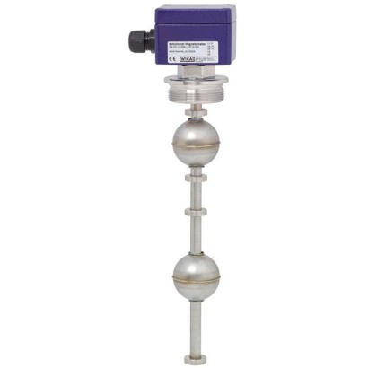
مفتاح تعويم
الوصف
يَتحرّك عوامة مزوّدة بمغناطيس دائم بشكل موثوق على طول مستوى السائل على أنبوب دليل. داخل أنبوب الدليل يتم تركيب مفتاح قصبي (تلامس غاز خامل)، يتم تنشيطه عبر الجدران غير المغناطيسية للعوامة وأنبوب الدليل عند اقتراب مغناطيس العوامة. وباستخدام مغناطيس ومفتاح قصبي تكون عملية التحويل بدون تلامس، وخالية من التآكل ولا تتطلب إمدادًا بالطاقة. إن التلامسات خالية من الجهد. كما تتوفر مفاتيح العوامة أيضًا بنقاط تحويل متعددة.
تُشير وظائف التحويل دائمًا إلى ارتفاع مستوى السائل: تلامس عادةً مفتوح، أو عادةً مغلق، أو تلامس تحويل.
لمزيد من الموافقات، راجع الصفحة 3
الشكل يسارًا: نسخة من الفولاذ المقاوم للصدأ، سنّ تركيب، الطراز FLS-S الشكل يمينًا: نسخة من البلاستيك، توصيل شَفْري، الطراز FLS-P
من خلال استخدام عوامة لحد أقصى 2 نقطة تحويل يمكن تحقيق سلوك مفتاح ثنائي الاستقرار، أي أن حالة التحويل تظل متاحة أيضًا عندما يستمر مستوى التعبئة في الارتفاع فوق نقطة التحويل أو الانخفاض تحتها.
مفتاح العوامة سهل التركيب وخالٍ من الصيانة، لذا تكون تكاليف التركيب والتشغيل والتكليف منخفضة.
المزايا
- نطاق تطبيقات واسع بفضل مبدأ التشغيل البسيط والمجرَّب
- لظروف التشغيل القاسية، وعمر تشغيلي طويل
- حدود التشغيل: درجة حرارة التشغيل: T = -50 ... +350 °C ضغط التشغيل: P = من الفراغ إلى 40 bar الكثافة الحدية: ρ ≥ 300 kg/m3
- درجة حرارة التشغيل: T = -50 ... +350 °C
- ضغط التشغيل: P = من الفراغ إلى 40 bar
- الكثافة الحدية: ρ ≥ 300 kg/m 3
- تشكيلة واسعة من الوصلات الكهربائية المختلفة، ووصلات العمليات والمواد
- نسخ مقاومة للانفجار
الأسئلة والأجوبة
ما هو نطاق قياس المستوى لمفتاح التعويم FLS؟
يمتد نطاق القياس من 0 إلى 6000 mm حسب بيانات المنتج.
ما هي درجة حرارة التشغيل المسموحة؟
تعمل العوامة عند درجات حرارة تشغيل من -50 … +350 °C.
ما الحد الأقصى لضغط العملية؟
يعمل المفتاح عند ضغط يصل إلى 40 bar، ومن التفريغ (Vacuum) حتى هذا الحد.
ما الكثافة الحدية للوسيط؟
يجب ألا تقل كثافة الوسيط عن ρ ≥ 300 kg/m³ ليتمكن المفتاح من العمل بشكل صحيح.
ما توصيلات العملية المتوفرة؟
تتوفر توصيلات G 1 1/"، G 2" وحسب DIN DN 50 … DN 200 و ANSI 2" … 8".
هل تتوفر إصدارات مقاومة للانفجار؟
نعم، تتوفر نسخ Ex i II 1/2G Ex ia IIC T6 ... T1 Ga/Gb II 2D Ex ib IIIC T80°C ... T230°C Db و Ex d II 2G Ex d IIC T6 Gb II 2D Ex tb IIIC T80 °C Db.
ما درجة حماية الدخول؟
تصنيف الحماية هو IP66/IP68.
ما الذي يميز FLS عن حلول قياس المستوى الأخرى؟
بفضل استخدام مغناطيس دائم ومفتاح قصبي تكون عملية التحويل بدون تلامس، خالية من التآكل ولا تتطلب إمدادًا بالطاقة، كما يمكن تحقيق سلوك مفتاح ثنائي الاستقرار باستخدام عوامة لحد أقصى نقطتي تحويل، مع إمكانية تعدد نقاط التحويل. ---
| الطراز | FLS-S |
| السلسلة | FLS |
| النوع الفرعي | float |
| نطاق المستوى | 0…6000 mm |
| وصلة العملية | G 1 1/2"G 2"DIN DN 50 ... DN 200ANSI 2" ... 8" |
| درجة حرارة العملية | −50…+350 °C |
| أقصى ضغط للعملية | 40 bar |
| تقنية القياس | float |
| إشارة الخرج | NO · NC · SPDT |
| التغذية | safety extra-low voltage |
| وصلة كهربائية | Connection housing Aluminium 64 x 58 x 34 mm, with 1 contact |
| مادة الأجزاء الملامسة | 1.4571 (316Ti), 1.4404 (316L), 1.4435 (316L), PP, PA, Ms, Buna, Titanium, Hastelloy |
| حرارة المحيط | −50…+350 °C |
| تصنيف IP | IP66/IP68 |
| الشهادات | CERoHSEACDNV GLABSBureau VeritasLloyd’s RegisterDIBt |
| حماية الانفجار | Ex i II 1/2G Ex ia IIC T6 ... T1 Ga/Gb II 2D Ex ib IIIC T80°C ... T230°C DbEx d II 2G Ex d IIC T6 Gb II 2D Ex tb IIIC T80 °C Db |
| لغات ورقة البيانات | EN, DE |
| Model | Description | Materials | ||||||||
|---|---|---|---|---|---|---|---|---|---|---|
| Stainless steel | Titanium 3.7035 (grade 2) | PVC / PP / PVDF | ||||||||
| 1.4571 (316Ti) | 1.4404 (316L) | 1.4435 (316L) | 1.4571 (316Ti) / PP | 1.4571 (316Ti) / PA | 1.4571 (316Ti) / Ms | 1.4571 (316Ti) / Buna | ||||
| FLS-SE | Standard version, cable connection, safety extra-low voltage | x | x | x | x | x | x | x | x | - |
| FLS-SF | Standard version, cable connection, low voltage | x | x | x | x | x | x | x | x | - |
| FLS-SA | Standard version, connection housing or connector, low voltage | x | x | x | x | x | x | x | x | - |
| FLS-SB | Standard version, connection housing or connector, safety extra-low voltage | x | x | x | x | x | x | x | x | - |
| FLS-SBI (60) | Intrinsically safe, Ex i | x | x | - | - | - | - | - | x | - |
| FLS-SAD FLS-SBD (AL-ADF) | Flameproof enclosure, Ex d | x | x | - | - | - | - | - | - | - |
| FLS-ME | Miniature design, cable connection, safety extra-low voltage | x | x | - | x | - | - | x | - | - |
| FLS-MB | Miniature design, connection housing or connector, safety extra-low voltage | x | x | - | x | - | - | x | - | - |
| FLS-PF | Plastic version, cable connection, low voltage | - | - | - | - | - | - | - | - | x |
| FLS-PA | Plastic version, connection housing or connector, low voltage | - | - | - | - | - | - | - | - | x |
| FLS-HE | Pharmaceutical version, cable connection, safety extra-low voltage | - | x | x | - | - | - | - | - | - |
| FLS-HA | Pharmaceutical version, connection housing, low voltage | - | x | x | - | - | - | - | - | - |
| FLS-HA3 | Sterile version (3-A), connection housing, low voltage | - | x | x | - | - | - | - | - | - |
| FLS-F | Food version, connection housing, low voltage | - | x | x | - | - | - | - | - | - |
| Models FLS-SE, FLS-SF, FLS-HE | -30 ...+180 °C |
|---|---|
| Models FLS-SA, FLS-SB | -50 ...+350 °C |
| Model FLS-SxI (60) | -50 ...+180 °C |
| Models FLS-SxD (AL-ADF) | -10 ...+120 °C |
| Model FLS-M | -10 ...+100 °C |
| Model FLS-P | -10 ...+100 °C |
| Models FLS-HA, FLS-HA3 | -40 ...+200 °C |
| Model FLS-F | -30 ...+180 °C |
| Logo | Description | Country |
|---|---|---|
| EU declaration of conformity ■ Low voltage directive ■ RoHS directive | European Union | |
| EAC ■ EMCdirective ■ Low voltage directive ■ Hazardous areas | Eurasian Economic Community | |
| DNV GL ■ Ships, shipbuilding (e.g. offshore) ■ Hazardous areas | International | |
| ABS ■ Ships, shipbuilding (e.g. offshore) ■ Hazardous areas | International | |
| Bureau Veritas Ships, shipbuilding | International | |
| APPROVED TYPE | Lloyd's Register Ships, shipbuilding (e.g. offshore) | International |
| - | DIBt Safety (e.g. electr. safety, overpressure, ...) Overflow control per German Water Resources Act (WHG) § 19 | Germany |
| Logo | Description | Country |
|---|---|---|
| EU declaration of conformity ■ Low voltage directive ■ RoHS directive | European Union | |
| EAC EMCdirective Low voltage directive | Eurasian Economic Community |
عرض الكل (20)
| Model FLS-SA, low voltage | Model FLS-SB, safety extra-low voltage | |
|---|---|---|
| Electrical connection | ■ Connection housing Aluminium 64 x 58 x 34 mm, with 1 contact Aluminium 80 x 75 x 57 mm, 2 or more contacts Option: Polypropylene, polyester, stainless steel ■ Coupler connector DIN EN 175301-803 (previously DIN 43650, 4-pin) M12 (4- or 8-pin) | |
| Process connection | ■ Mounting thread downwards G11/2" G2" Others on request ■ Mounting flange DIN DN 50 ...DN 200, PN 6 ...PN 100 DIN EN 1092-1 DN 50 ...DN 200, PN 6 ...PN 100 ANSI 2' ... 8', Class 150 ...600 | |
| Guide tube diameter | 12mm/14mm/18mm | |
| Guide tube length L | ≤ 3,000 mmfor guide tube diameter 12 or14mm ≤ 6,000 mmfor guide tube diameter18mm | |
| Float | Material: Stainless steel 1.4571 (option: Buna (NBR), titanium) Float diameter: 44 ...120mm Float selection depending on guide tube diameter and process conditions (see page 16, 17, 18) | |
| Temperature range | Observe the temperature range of the float and the connection housing Temperature range of the connector on request | |
| Standard version | -30 ...+180 °C | |
| High-temperature version | -30 ...+250 °C | |
| Low-temperature version | -50 ...+180 °C | |
| Maximum temperature version | -30 ...+350 °C | |
| Switching function | Alternatively normally open (NO), normally closed (NC) or change-over (SPDT) contact - on rising level | |
| Max. number of contacts | 6 x NOor NC, or 4 x SPDT | |
| Switch position | Dimensions L1, L2, L3 ... (from sealing face, starting from top) | |
| Distance between switch points | Minimum 20 mm(depending on the selection of the float and the contacts) | |
| Switching power | ||
| Normally open, normally closed | AC ≤ 230 V; 100 VA; 1 A DC ≤ 230 V; 50 W;0.5 A | AC < 50 V; 100 VA; 1 A DC < 75 V; 50 W;0.5 A |
| Change-over | AC ≤ 230 V; 40 VA; 1 A DC ≤ 230 V; 20 W;0.5 A | AC < 50 V; 40 VA; 1 A DC < 75 V; 20 W;0.5 A |
| Mounting position | Vertical ±30° |
| Model FLS-SF, low voltage | Model FLS-SE, safety extra-low voltage | |
|---|---|---|
| Electrical connection | Connection cable ■ PVC ■ Silicone ■ PUR | |
| Process connection | Mounting thread upwards:G⅜"or G½" Others on request | |
| Guide tube diameter | 12mm/14mm/18mm | |
| Guide tube length L | ≤ 3,000 mmfor guide tube diameter 12 or14mm ≤ 6,000 mmfor guide tube diameter18mm | |
| Float | Material: Stainless steel 1.4571 (option: Buna (NBR), titanium) Float diameter: 44 ...120mm Float selection depending on guide tube diameter and process conditions (see page 16, 17, 18) | |
| Temperature range | ||
| PVC/PUR cable | -10 ...+80 °C | |
| Silicone cable | -30 ...+180 °C | |
| Observe the temperature range of the float | ||
| Switching function | Alternatively normally open (NO), normally closed (NC) or change-over (SPDT) contact - on rising level | |
| Max. number of contacts | 6 x NOor NC, or 4 x SPDT for PVC and PUR cable 5 x NOor NC, or 3 x SPDT for silicone cable | |
| Switch position | Dimensions L1, L2, L3 ... (from sealing face, starting from top) | |
| Distance between switch points | Minimum 20 mm(depending on the selection of the float and the contacts) | |
| Switching power | ||
| Normally open, normally closed | AC ≤ 230 V; 100 VA; 1 A DC ≤ 230 V; 50 W;0.5 A | AC < 50 V; 100 VA; 1 A DC < 75 V; 50 W;0.5 A |
| Change-over | AC ≤ 230 V; 40 VA; 1 A DC ≤ 230 V; 20 W;0.5 A | AC < 50 V; 40 VA; 1 A DC < 75 V; 20 W;0.5 A |
| Mounting position | Vertical ±30° |
| Model FLS-SBI | ||||||
|---|---|---|---|---|---|---|
| Electrical connection | Connection housing: Aluminium | |||||
| Option: Polyester, stainless steel | ||||||
| Process connection | ■ Mounting thread downwards G11/2" or G2" ■ Mounting flange - DIN DN 50 ...DN 200, PN 6 ...PN 100 - DIN EN 1092 DN 50 ...DN 200, PN 6 ...PN 100 - ANSI 2" ... 8", Class 150 ...600 Others on request | |||||
| Guide tube diameter | 12mm/14mm/18mm | |||||
| Guide tube length L | ≤ 3,000 mmfor guide tube diameter 12 or14mm ≤ 6,000 mmfor guide tube diameter18mm | |||||
| Float | Material: Stainless steel 1.4571 (option: Buna (NBR), titanium) Float diameter: 44 ...120mm Float selection depending on guide tube diameter and process conditions (see page 16, 17, 18) | |||||
| Temperature class | T1 | T2 | T3 | T4 | T5 | T6 |
| Process temperature | Max. 180 °C | Max. 180 °C | Max. 180 °C | Max. 130 °C | Max. 95 °C | Max. 80 °C |
| Ambient temperature at connection housing (T a ) | Max. 80 °C | Max. 80 °C | Max. 80 °C | Max. 80 °C | Max. 65 °C | Max. 50 °C |
| →Versions with optional circuits (e g. resistor connection, NAMURor temperature contacts), as well as surface temperature (EPL Db) at dust protection see operating instructions | ||||||
| Switching function | Alternatively normally open (NO), normally closed (NC) or change-over (SPDT) contact - on rising level | |||||
| Max. number of contacts | 6 x NOor NC, or 4 x SPDT for guide tube diameter 12, 14 or18mm | |||||
| Switch position | Dimensions L1, L2, L3 ... (from sealing face, starting from top) | |||||
| Distance between switch points | Minimum 20 mm(depending on the selection of the float and the contacts) | |||||
| Switching power | Only for connection to a certified intrinsically safe circuit with max. | |||||
| U i = 36V | I i = 100mA | C i = 0 nF | L i = 0 μH | |||
| Mounting position | Vertical ±30° |
| Model FLS-SAD | Model FLS-SBD | |
|---|---|---|
| Electrical connection | Connection housing: Aluminium Option: Stainless steel | |
| Process connection | ■ Mounting thread downwards G11/2" or G2" ■ Mounting flange DIN DN 50 ...DN 350, PN 6 ...PN 40 ANSI 2" ... 14", Class 150 ...300 | |
| Guide tube diameter | 12mm/14mm | |
| Guide tube length L | ≤ 4,000 mmfor guide tube diameter12mm ≤ 6,000 mmfor guide tube diameter14mm | |
| Float | Material: Stainless steel 1.4571 Float diameter: 44 ...80mm Float selection depending on guide tube diameter and process conditions (see page 16, 17, 18) | |
| Temperature range (process temperature) | T4 T5 T6 ≤ 120 °C ≤ 95 °C ≤ 80 °C | |
| Switching function | Change-over SPDT - on rising level | |
| Max. number of contacts | 4 x SPDT | |
| Switch position | Dimensions L1, L2, L3 ... (from sealing face, starting from top) | |
| Distance between switch points | Minimum 20 mm(depending on the selection of the float and the contacts) | |
| Switching power | AC ≤ 230 V; 100 VA; 1.5 A DC ≤ 230 V; 60 W;1.5 A | ■ With series resistance AC < 50V;40VA;150mA DC < 75V;20W;150mA ■ With NAMUR circuit per DIN EN 60947-5-6 AC < 50V;40VA;7mA DC < 75V;20W;7mA |
| Mounting position | Vertical ±30° |
| Model FLS-ME | Model FLS-MB | |||
|---|---|---|---|---|
| Electrical connection | Connection cable ■ PVC ■ Silicone ■ PUR | ■ Connection housing: Aluminium 64 x 58x34mm ■ Coupler connector DIN EN 175301-803 (previously DIN 43650, 4-pin) M12 (4- or 8-pin) | ||
| Process connection | Mounting thread upwards G1/8" Others on request | Mounting thread downwards G3/4" or G1" Others on request | ||
| Guide tube diameter | 8mm | |||
| Guide tube length L | ≤ 500mm | |||
| Float | Material: Stainless steel 1.4571 (option: Buna (NBR), titanium, PP) Float diameter from 20 ...35mm Float selection depending on guide tube diameter and process conditions (see page 16, 17, 18) | |||
| Temperature range | PVC/PUR cable | -10 ...+80 °C | Buna (NBR), PP | -10 ...+80 °C |
| Silicone cable | -30 ...+150 °C | Stainless steel, titanium | -30 ...+150 °C | |
| Observe the permissible temperature range of the float. | ||||
| Switching function | Alternatively normally open (NO), normally closed (NC) or change-over (SPDT) contact - on rising level | |||
| Max. number of contacts | 3 x NOor NC, or 2 x SPDT | |||
| Switch position | Dimensions L1, L2, L3 ... (from sealing face, starting from top) | |||
| Distance between switch points | Minimum 20 mm(depending on the selection of the float and the contacts) | |||
| Switching power | ||||
| Normally open, normally closed | AC < 50 V; 10 VA; 0.5 A | DC < 75 V; 5 W;0.25 A | ||
| Change-over | AC < 50 V; 5 VA; 0.25 A | DC < 75 V; 2.5 W;0.15 A | ||
| Versions FLS-MF, FLS-MA 1) | AC ≤ 230 V; 10 VA; 0.5 A | DC ≤ 230 V; 5 W;0.25 A | ||
| Mounting position | Vertical ±30° |
| Model FLS-PF | Model FLS-PA | |
|---|---|---|
| Electrical connection | Connection cable ■ PVC ■ PUR | ■ Connection housing Polypropylene 80 x 82x55mm Polyester 80 x 75x55mm ■ Coupler connector DIN EN 175301-803 (previously DIN 43650, 4-pin) M12 (4- or 8-pin) |
| Process connection | Mounting thread upwards G3/8" others on request | Mounting thread downwards ■ G11/2" ■ G2" Flange ■ DIN DN50 ...DN200, PN 6 ...PN 100 ■ DIN EN 1092-1 DN50 ...DN200, PN6...PN 100 ■ ANSI 2" ... 8", Class 150 ...600 |
| Guide tube diameter | 12mm/16mm/20mm | |
| Guide tube length L | ≤ 500 mmfor guide tube diameter12mm ≤ 3,000 mmfor guide tube diameter16mm ≤ 5,000 mmfor guide tube diameter20mm | |
| Float | Material: PVC, PP or PVDF Float diameter from 44 ...80mm Float selection depending on guide tube diameter and process conditions (see page 16, 17, 18) | |
| Temperature range | For float material PVC 0 ... 60 °C For float material PP -10 ...+80 °C For float material PVDF -10 ...+100 °C | |
| Switching function | Alternatively normally open (NO), normally closed (NC) or change-over (SPDT) contact - on rising level | |
| Max. number of contacts | 6 x NOor NC, or 4 x SPDT | |
| Switch position | Dimensions L1, L2, L3 ... (from sealing face, starting from top) | |
| Distance between switch points | Minimum 20 mm(depending on the selection of the float and the contacts) | |
| Switching power | ||
| Normally open, normally closed | AC ≤ 230 V; 100 VA; 1 A | DC ≤ 230 V; 50 W;0.5 A |
| Change-over | AC ≤ 230V ; 40 VA; 1 A | DC ≤ 230 V; 20 W;0.5 A |
| Mounting position | Vertical ±30° |
| Model FLS-HA | Model FLS-HE | ||
|---|---|---|---|
| Electrical connection | Connection housing: ■ Stainless steel | Connection cable ■ PVC ■ Silicone ■ PUR | |
| Process connection | ■ Mounting thread upwards G3/8" ■ Mounting flange per DIN or ANSI ■ Threaded connection per DIN 11851 ■ Clamp pipe connection per DIN 32676 ■ Ingold connection Others on request | ||
| Guide tube diameter | 17.2 mm(stainless steel 1.4435 or 1.4539, surface ground and polished) | ||
| Guide tube length L | ≤ 5,000mm | ||
| Float | Material: Stainless steel 1.4435 or 1.4539 Float diameter from 44 ...120mm Float selection depending on guide tube diameter and process conditions (see page 16, 17, 18) | ||
| Temperature range | PVC/PUR cable | -10 ...+80 °C | |
| Silicone cable | -30 ...+150 °C | ||
| Switching function | Alternatively normally open (NO), normally closed (NC) or change-over (SPDT) contact - on rising level | ||
| Max. number of contacts | 6 x NOor NC, or 4 x SPDT | 6 x NOor NC, or 4 x SPDT for PVC and PUR cable 3 x NOor NC, or 2 x SPDT for silicone cable | |
| Switch position | Dimensions L1, L2, L3 ... (from sealing face, starting from top) | ||
| Distance between switch points | Minimum 20 mm(depending on the selection of the float and the contacts) | ||
| Switching power | |||
| Normally open, normally closed | AC ≤ 230 V; 100 VA; 1 A DC ≤ 230 V; 50 W;0.5 A | AC < 50 V; 100 VA; 1 A DC < 50 V; 50 W;0.5 A | |
| Change-over | AC ≤ 230V ; 40 VA; 1 A DC ≤ 230 V; 20 W;0.5 A | AC < 50 V; 40 VA; 1 A DC < 50 V; 20 W;0.5 A | |
| Mounting position | Vertical ±30° |
| Model FLS-HA3 with separate float bracket | Model FLS-HA3 with welded pipe connection | |
|---|---|---|
| Electrical connection | Connection housing: stainless steel | |
| Process connection | ■ Clamp pipe connection ISO 2852, DN 32 …DN100or 1.5" …4" ■ Clamp pipe connection DIN 32676, DN 32 …DN100or 1.5" …4" ■ Aseptic mounting thread downwards DIN 11864-1, DN 32 ...DN 100 or 1.5" ... 4" ■ Aseptic liner DIN 11864-1, DN 32 ...DN 100 or 1.5" ... 4" ■ Aseptic flange connection DIN 11864-2 (DN 32 ...DN 50 or 1.5" ... 2" ■ Aseptic clamp connection DIN 11864-3, DN 32 ...DN 100 or 1.5" ... 4" ■ VARIVENT ® (form F,N and G) ■ BioConnect ® threaded connection, DN 32 …DN100or 1,5" …2" ■ BioConnect ® flange connection, DN 32 …DN100or 1.5" …2" ■ BioConnect ® clamp connection, DN 32 …DN100or 1.5" …4" | |
| Guide tube diameter | 12 mm/ 14 mm/ 17.2 mm(stainless steel 1.4435 or 1.4539, surface ground or polished, R a < 0.8 µm) | |
| Guide tube length L | ≤ 5,000mm | |
| Float | Material: Stainless steel 1.4435 or 1.4539 Float diameter:50 ...80mm Float selection depending on guide tube diameter and process conditions (see page 16, 17, 18) | |
| Temperature range | ||
| Process temperature | -40 ...+200 °C | |
| Ambient temperature | -40 ...+85 °C | |
| Switching function | Alternatively normally open (NO), normally closed (NC) or change-over (SPDT) contact - on rising level | |
| Max. number of contacts | 3 x NOor NC, or 3 x SPDT | |
| Switch position | Dimensions L1, L2, L3 ... (from sealing face, starting from top) | |
| Distance between switch points | Minimum 50 mm(depending on the selection of the float and the contacts) | |
| Switching power | ||
| Normally open, normally closed | AC ≤ 230 V; 100 VA; 1 A DC ≤ 230 V; 50 W;0.5 A | |
| Change-over | AC ≤ 230V ; 40 VA; 1 A DC ≤ 230 V; 20 W;0.5 A | |
| Mounting position | Vertical ±30° |
| Model | Angled version | Adjustable guide tube | ECTFE coating | Special flange from polyamide or brass | Food version |
|---|---|---|---|---|---|
| FLS-SE | x | x | - | - | x |
| FLS-SF | x | x | - | - | x |
| FLS-SA | x | x | x | x | x |
| FLS-SB | x | x | x | x | x |
| FLS-SBI (60) | x | - | - | - | - |
| FLS-ME | x | x | - | - | - |
| FLS-MB | x | x | - | - | - |
| FLS-PF | x | - | - | - | - |
| FLS-PA | x | - | - | - | - |
| Threaded pipe connection | Clamp pipe connection | |
|---|---|---|
| Electrical connection | Connection housing: ■ Aluminium 64 x 58 x 34 mm, with 1 contact ■ Aluminium 80 x 75 x 57 mm, 2 or more contacts Option: Polypropylene, polyester, stainless steel | |
| Process connection | Threaded pipe connection per DIN 11851, downwards DN 50 ...DN 150 others on request | Clamp pipe connection per DIN 32676, DN 25 …DN100or 1" …4" others on request |
| Guide tube diameter | 12mm/14mm/18mm | |
| Guide tube length L | ≤ 3,000 mmfor guide tube diameter 12 or14mm ≤ 6,000 mmfor guide tube diameter18mm | |
| Float | Material stainless steel 1.4435 or 1.4404, option electropolished Float diameter from 44 ...80mm Float selection depending on guide tube diameter and process conditions (see page 16, 17, 18) | |
| Temperature range (process temperature) | -30 ...+180 °C | |
| Switching function | Alternatively normally open (NO), normally closed (NC) or change-over (SPDT) contact - on rising level | |
| Max. number of contacts | 3 x NOor NC, or 3 x SPDT | |
| Switch position | Dimensions L1, L2, L3 ... (from sealing face, starting from | top) |
| Distance between switch points | Minimum 50 mm(depending on the selection of the float and the contacts) | |
| Switching power | ||
| Normally open, normally closed | AC ≤ 230 V; 100 VA; 1 A DC ≤ 230 V; 50 W;0.5 A | |
| Change-over | AC ≤ 230V ; 40 VA; 1 A DC ≤ 230 V; 20 W;0.5 A | |
| Mounting position | Vertical ±30° |
| Material | Version | Suits guide tube Ø inmm | Ø A inmm | B inmm | Ø C inmm | Max. operating pressure in bar | Max. operating temp. in °C | Limit density 85% in kg/m 3 | Order no. |
|---|---|---|---|---|---|---|---|---|---|
| Stainless steel 1.4571 | V29A | 8 | 29 | 28 | 9 | 25 | 100 | 920 | 027355 |
| V52A | 12 | 52 | 52 | 15 | 40 | 250 | 700 | 005462 | |
| V52T | 12 | 52 | 52 | 15 | 40 | 350 | 730 | 033560 | |
| V62A | 12 | 62 | 61 | 15 | 32 | 250 | 590 | 005473 | |
| V83A | 12 | 83 | 81 | 15 | 25 | 250 | 430 | 005485 | |
| V80A | 18 | 80 | 76 | 23 | 25 | 250 | 680 | 005478 | |
| V98A | 18 | 98 | 96 | 23 | 25 | 250 | 600 | 005489 | |
| V105A | 18 | 105 | 103 | 23 | 25 | 250 | 530 | 020652 | |
| V120A | 18 | 120 | 117 | 23 | 25 | 250 | 390 | 021721 | |
| Titanium 3.7035 | T29A | 8 | 29 | 28 | 9 | 30 | 100 | 700 | 005522 |
| T52A | 12 | 52 | 52 | 15 | 25 | 300 | 570 | 005525 | |
| T62A | 12 | 62 | 62 | 15 | 25 | 300 | 505 | 005536 | |
| T83A | 12 | 83 | 81 | 15 | 25 | 300 | 350 | 005544 | |
| T80A | 18 | 80 | 76 | 23 | 25 | 300 | 665 | 112263 | |
| T98A | 18 | 98 | 96 | 23 | 25 | 300 | 495 | - | |
| T105A | 18 | 105 | 103 | 23 | 25 | 300 | 370 | - | |
| T120A | 18 | 120 | 117 | 23 | 25 | 300 | 330 | - | |
| Stainless steel 1.4571 ECTFE coated | VEC53A | 12 | 53 | 53 | 14 | 25 | Depending on medium | 850 | 111415 |
| VEC63A | 12 | 63 | 62 | 14 | 25 | Depending on medium | 590 | - | |
| VEC84A | 12 | 84 | 82 | 14 | 25 | Depending on medium | 400 | - | |
| VEC81A | 18 | 81 | 77 | 22 | 25 | Depending on medium | 720 | - | |
| VEC99A | 18 | 99 | 97 | 22 | 25 | Depending on medium | 675 | - | |
| VEC106A | 18 | 106 | 104 | 22 | 25 | Depending on medium | 630 | - | |
| VEC121A | 18 | 121 | 118 | 22 | 25 | Depending on medium | 460 | - |
| Material | Version | Suits guide tube Ø inmm | Ø A inmm | B inmm | Ø C inmm | Max. operating pressure in bar | Max. operating temp. in °C | Limit density 85% in kg/m 3 | Order no. |
|---|---|---|---|---|---|---|---|---|---|
| Stainless steel 1.4571 | V27A | 8 | 27 | 31 | 10 | 16 | 100 | 787 | 009679 |
| V29A/40 | 12 | 29 | 40 | 13,4 | 10 | 180 | 720 | 030352 | |
| V44A | 12 | 44 | 52 | 15 | 16 | 300 | 720 | 009681 | |
| V44T | 12 | 44 | 52 | 15 | 16 | 350 | 780 | 033561 | |
| Titanium 3.7035 | T44A | 12 | 44 | 52 | 15 | 16 | 300 | 720 | 009744 |
| Buna (NBR) | B20A | 8 | 20 | 20 | 9 | 3 | 80 | 940 | 009719 |
| B23A | 8 | 23 | 25 | 9 | 3 | 80 | 800 | 009721 | |
| B25A | 8 | 25 | 14 | 9 | 3 | 80 | 790 | 009720 | |
| B30A | 8 | 30 | 45 | 13 | 3 | 80 | 680 | 034047 | |
| B40A | 12 | 40 | 30 | 15 | 3 | 80 | 580 | 009728 | |
| B40A/120 | 12 | 40 | 120 | 15 | 3 | 80 | 410 | 14377687 | |
| B50A | 18 | 50 | 45 | 19 | 3 | 80 | 500 | 009725 | |
| PVC | P44A | 12 | 44 | 44 | 14 | 3 | 60 | 650 | 033790 |
| P55A | 16 | 55 | 54 | 22 | 3 | 60 | 800 | 033793 | |
| P80A | 20 | 80 | 79 | 25 | 3 | 60 | 570 | 033796 | |
| Polypropylene | PP27A | 8 | 27 | 29 | 9 | 3 | 80 | 755 | 015516 |
| PP35A | 8 | 35 | 33 | 9 | 3 | 80 | 675 | 100347 | |
| PP44A | 12 | 44 | 44 | 14 | 3 | 80 | 480 | 015514 | |
| PP55A | 16 | 55 | 54 | 22 | 3 | 80 | 580 | 033792 | |
| PP80A | 20 | 80 | 79 | 25 | 3 | 80 | 430 | 033795 | |
| PVDF | PF44A | 12 | 44 | 55 | 14 | 3 | 100 | 780 | 033791 |
| PF55A | 16 | 55 | 69 | 22 | 3 | 100 | 820 | 116235 | |
| PF80A | 20 | 80 | 79 | 25 | 3 | 100 | 680 | 033797 | |
| Stainless steel 1.4571 E-CTFE coated | VEC45A | 12 | 45 | 53 | 14 | 16 | Depending on medium | 891 | 114412 |
| Material | Model | Suits guide tube Ø inmm | Ø A inmm | B inmm | Ø C inmm | Max. operating pressure in bar | Max. operating temp. in °C | Limit density 85% in kg/m 3 | Order no. |
|---|---|---|---|---|---|---|---|---|---|
| Stainless steel 1.4435 | V80/88/A34/3A/35, axial | 18 | 80 | 55 | 23 | 16 | 250 | 790 | 129383 |
| V50/55/17/ A34/3A/35 | 12 | 50 | 55 | 16.8 | 16 | 250 | 955 | 129583 | |
| V55/70/A34/ 3A/35 axial | 12 | 55 | 70 | 17 | 16 | 250 | 780 | 14462858 |
| Contact protection relays | Contacts | Input | Power supply | Ex marking | Order no. |
|---|---|---|---|---|---|
| KFD2-ER-1.6 | 1 x change-over AC 250 V, 2 A | 2 x contacts | DC 20 ...30V | - | 123806 |
| KFD2-SR2-Ex2.W | 2 x change-over AC 253 V, 2 A | 2 x contacts | DC 20 ...30V | II 1GD Ex ia IIC | 124344 |
| KFA6-ER-1.6 | 1 x change-over AC 250 V, 2 A | 2 x contacts | AC 230V | - | 124341 |
| KFA6-SR2-Ex2.W | 2 x change-over AC 253 V, 2 A | 2 x contacts | AC 230V | II 1GD Ex ia IIC | 123794 |
| RC element | Capacitance | Resistance | Voltage | Order no. |
|---|---|---|---|---|
| B3/110 | 0.33 µF | 470Ω | AC 110V | 126529 |
| B3/230 | 0.33 µF | 820Ω | AC 230V | 126530 |
| Logo | Description | Country |
|---|---|---|
| EU declaration of conformity ■ Directive for nuclear facilities IEC/IEEE 60780-323 ■ RoHS directive ■ ATEX directive (option) Hazardous areas - Ex i Zone 0, gas II 1/2G Ex ia IIC T6 ...T1 Ga/Gb Zone 1, gas II 2G Ex d IIC T6 Gb | European Union | |
| Zone 0, dust II 2D Ex ib IIIC T80 ...T230 Zone 1, dust II 2D Ex tb IIIC T80 °C Db (option) Ships, shipbuilding (e.g. offshore) | International | |
| DNV ■ ■ Hazardous areas | ||
| ABS (option) Ships, shipbuilding (e.g. offshore) | International |
لم تجد الإجابة في الوثائق؟ سيرد المهندس خلال يوم عمل.
اسأل المهندس →