
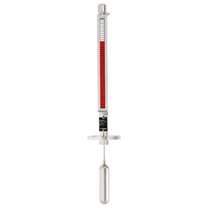
Top-mounted level indicator
Description
The model UTN top-mounted level indicator consists of a measuring chamber, a float with guide rod and a magnetic system. Mounting onto the vessel is made via appropriate process connections (flange, thread).
The permanent magnetic system, which is connected to the float via a guide rod, transmits the liquid level measured in the vessel by the float, contact-free, to the magnetic display mounted to the outside of the measuring chamber. In this magnetic display there are red/white plastic rollers or stainless steel flaps with bar magnets fitted at 10 mm intervals. The magnetic rollers or flaps are turned 180° through the walls of the measuring chamber. For an increasing level from white to red; for a falling level from red to white. Thus the magnetic display indicates the level of a vessel as a red column, without power supply.
for further approvals see page 3
Top-mounted level indicator, model UTN
Special features
- Process- and procedure-specific production
- Operating limits: Operating temperature: T = -60 ... +300 °C Operating pressure: P = Vacuum to 40 bar
- Operating temperature: T = -60 ... +300 °C
- Operating pressure: P = Vacuum to 40 bar
- Wide variety of different process connections
- Mounting of level sensors and magnetic switches possible as an option
- Explosion-protected versions
| Model | UTN |
| Subcategory | Top-mounted level indicator with magnetic display |
| Level ranges | 0…3 m |
| Process connection | DIN EN 1092-1: DN 50 ... DN 250, PN 6 ... PN 64ASME B16.5: 2" ... 10", class 150 ... 600G 2" threadG2 thread |
| Process temperature | −196…+300 °C |
| Max process pressure | 40 bar |
| Measurement technology | float |
| Output signal | mechanical magnetic display (no power required) · binary signal (with magnetic switch BGU) · analogue signal (with reed sensor BLR or magnetostrictive sensor BLM) · magnetic display (visual indication) · binary signal (via optional magnetic switch BGU) · analogue signal (via optional level sensors BLR/BLM) · binary (magnetic switch) · resistance (reed sensor) |
| Power supply | Not required for magnetic display; optional sensors may require power |
| Wetted parts material | Stainless steel 1.4571 (316Ti), Stainless steel 1.4401/1.4404 (316/316L), Titanium 3.7035, Titanium 3.7025 |
| Ambient temperature | −60…+300 °C |
| IP rating | IP65 |
| Certifications | CEEACGOST |
| Explosion protection | ATEX II 1G c T1 ... T6KEMA 02 ATEX 2106 X II 1/2G c T1 ... T6ATEX directive: Hazardous areas Ex c Zone 0/1, gas II 1G c T1 ... T6 or KEMA 02 ATEX 2106Ex c Zone 0/1, gas II 1G c T1 ...T6 or KEMA 02 ATEX 2106 XII 1/2G c T1 ...T6 |
| Datasheet languages | EN, DE |
| Top-mounted level indicator model | Description | Material | Max. pressure in bar | Medium temperature in °C |
|---|---|---|---|---|
| UTN-C | 42 mmversion | Stainless steel 1.4571 (316Ti) | 40 | -120 ...+300 |
| (standard) | Stainless steel 1.4401/1.4404 (316/316L) | 40 | -196 ...+300 | |
| UTN-S | 60 mmversion | Stainless steel 1.4571 (316Ti) | 40 | -120 ...+300 |
| Stainless steel 1.4401/1.4404 (316/316L) | 40 | -196 ...+300 |
| Model | DGRL | ATEX | CE |
|---|---|---|---|
| UTN-C00 UTN-S00 | - | - | - |
| UTN-CA1, UTN-CA2, UTN-CBD, UTN-CGE, UTN-CBC UTN-SA1, UTN-SA2, UTN-SBD, UTN-SGE, UTN-SBC | x | - | x |
| UTN-C00C UTN-S00C | - | x | x |
| UTN-CA1C, UTN-CA2C, UTN-CBDC, UTN-CGEC, UTN-CBC UTN-SA1C, UTN-SA2C, UTN-SBDC, UTN-SGEC, UTN-SBC | x | x | x |
| Logo | Description | Country |
|---|---|---|
| EU declaration of conformity ■ Pressure equipment directive (option) ■ ATEX directive (option) Hazardous areas Ex c Zone 0/1, gas II 1G c T1 ...T6 or KEMA 02 ATEX 2106 | European Union | |
| EAC ■ EMCdirective (in connection with mounted components) No.RU D-DE.A301.B.00815 ■ Pressure equipment directive No.RU D-DE.MJU62.B.02027 | Eurasian Economic Community | |
| GOST (in connection with reed sensor) Metrology, measurement technology No. 19358 | Russia |
| Specifications | |
|---|---|
| Measuring chamber | Ø42.4 x 2 or Ø42.2 x 2.77 |
| Chamber end top | Flat top or pipe cap Options: Vent plug G1/2" |
| Process connection | ■ Mounting thread G2" ■ Mounting flange - DIN EN 1092-1: DN 50 ...DN 250, PN 6 ...PN 64 - ASMEB16.5: 2" ... 10", class 150 ...600 |
| Material ■ Measuring chamber, process connection ■ Guide rod ■ Float | Stainless steel 1.4571 (316 Ti), 1.4401/1.4404 (316/316L) Titanium 3.7035 Stainless steel 1.4571 or titanium 3.7025 other materials on request |
| Nominal pressure | max. 40 bar |
| Temperature range ■ 1.4571 (316 Ti) ■ 1.4401/1.4404 (316/316L) | -120 ...+300 °C -196 ...+300 °C |
| Max. insertion length L | 3,000mm Other versions on request With large lengths and lateral flows, a stilling well is recommended. |
| Top stand-off T | Standard 100mm |
| Bottom stand-off U | min.140mm |
| Guiding sleeve length X | min.25mm |
| Float | see table page 6 |
| Magnetic display | Model BMD-SA:< 200 °C Model BMD-FA: > 200 °C For specifications, other versions and options see magnetic display for bypass level indicator, modelBMD (data sheet LM 10.03) |
| Further options ■ Magnetic switch ■ Reed sensor | Model BGU, see data sheet LM 10.06 Model BLR, see data sheet LM 10.04 |
View all (6)
| Specifications | |
|---|---|
| Measuring chamber | Ø60.3 x 2 or Ø60.3 x 2.77 |
| Chamber end top | Flat top or pipe cap Options: Vent plug G1/2" |
| Process connection | Mounting flange - DIN EN 1092-1: DN 50 ...DN 250, PN 6 ...PN 64 - ASMEB16.5: 2" ... 10", class 150 ...600 |
| Material | |
| ■ Measuring chamber, process connection ■ Guide rod ■ Float | Stainless steel 1.4571 (316 Ti), 1.4401/1.4404 (316/316L) Titanium 3.7035 Stainless steel 1.4571 or titanium 3.7025 other materials on request |
| Nominal pressure | max. 40 bar |
| Temperature range | |
| ■ 1.4571 (316 Ti) ■ 1.4401/1.4404 (316/316L) | -120 ...+300 °C -196 ...+300 °C |
| Max. insertion length L | 3,000mm Other versions on request With large lengths and lateral flows, a stilling well is recommended. |
| Top stand-off T | Standard 100mm |
| Bottom stand-off U | min.140mm |
| Guiding sleeve length X | min.25mm |
| Float | see table page 6 |
| Magnetic display | Model BMD-SA:< 200 °C Model BMD-FA: > 200 °C For specifications, other versions and options see magnetic display for bypass level indicator, modelBMD (data sheet LM 10.03) |
| Further options | |
| ■ Magnetic switch ■ Reed sensor ■ Magnetostrictive sensor | Model BGU, see data sheet LM 10.06 Model BLR, see data sheet LM 10.04 Model BLM, see data sheet LM 10.05 |
| Float | Form | Material | Pressure range |
|---|---|---|---|
| L = 200 ...400mm 50 ...75mm D = | Cylinder (ZVS... / ZTS...) | Stainless steel 1.4571 or titanium | to 40 bar |
| D D = 80 ...120mm | Ball (V... / T...) | Stainless steel 1.4571 or titanium | to 40 bar |
Couldn't find the answer in the documentation? An engineer will reply within a business day.
Ask an engineer →