
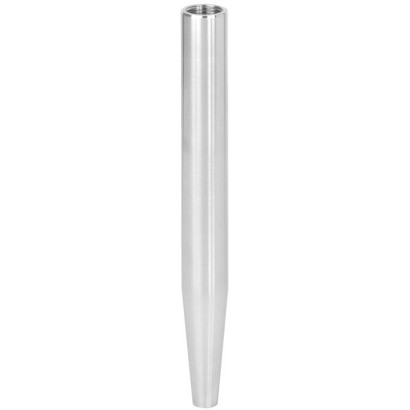
Thermowell for weld-in or with flange
Description
Each thermowell is an important component of any temperature measuring location. It is used to separate the process from the surrounding area, thus protecting the environment and operating personnel and keeps aggressive media, high pressures and flow rates from the temperature probe itself and thereby enables the thermometer to be exchanged during operation.
Based on the almost limitless application possibilities, there are a large number of variants, such as thermowell designs or materials. The type of process connection and the basic method of manufacture are important design differentiation criteria. A basic differentiation can be made between threaded and weld-in thermowells, and those with flange connections.
Special features
- Version per DIN 43772
- Model TW55-6: Form 4 to weld-in Model TW55-7: Form 4F with flange
- For highly corrosion-resistant coating (model TW55-7)
Build a TW55 for your task
The article number is assembled automatically. If unsure — ask an engineer; we'll match the line's parameters.
- Thermowell styleForm 4 (welding connection)
- Bar diameter [Bd or F2]24 mm
- Connection to thermometer [N]M18 x 1,5 female
- Bore size [B or d1]0.276 inch (7.0 mm)
- Flange sizeWithout
- Pressure ratingWithout
- Flange faceWithout
- MaterialStainless steel 1.4571
- Total length [L]—
- Insertion length [U1]0
- Tapering length [U]—
- CertificatesWithout
Finish your configuration
Select every option to submit the request.
| Model | TW55 |
| Subcategory | Thermowell |
| Process connection | EN 1092-1DIN 2527ASMEWeld-in (TW55-6)Flange (TW55-7)M14 x 1.5 female threadM18 x 1.5 female threadG½ female threadG¾ female threadweld-inflange |
| Thermowell material | 1.4571, 316/316L, P250GH, 1.5415, 1.7380, Stainless steel 1.4571, Stainless steel 316/316L, Steel P250GH, Steel 1.5415, Steel 1.7380 |
| Certifications | 3.1 inspection certificate2.2 test report |
| Thermowell | Yes |
| Thermowell form | 4F |
| Datasheet languages | EN |
| Models TW55-6 and TW55-7 | |
|---|---|
| Designs per DIN 43772 | ■ Design TW55-6: Form 4 to weld-in ■ Design TW55-7: Form 4F with flange, for highly corrosion-resistant coatings |
| Thermowell materials | ■ Stainless steel 1.4571 ■ Stainless steel 316/316L ■ Steel P250GH (former designation: 1.0460, C22.8) ■ Steel 1.5415 ■ Steel 1.7380 |
| Process connection 1) | |
| Thermowell outer diameter (bar diameter) | ■ Ø18 mm[0.71 in] ■ Ø24 mm[0.94 in] ■ Ø26 mm[1.02 in] ■ Ø32 mm[1.26 in] |
| Flanges to valid national or international standards | ■ EN 1092-1 ■ DIN 2527 ■ ASME |
| Connection to thermometer | ■ M14 x 1.5 female thread ■ M18 x 1.5 female thread ■ G½female thread ■ G¾female thread |
| Bore size | ■ Ø3.5 mm[0.14 in] ■ Ø7mm[0.28 in] ■ Ø9mm[0.35 in] ■ Ø11 mm[0.43 in] |
| Insertion length U 1 , cone length U and overall length L | For design combinations, see table page 4 |
| Coating | |
| PFA | ■ Layer thickness min.0.4mm ■ Layer thickness min.0.6mm |
| ECTFE (Halar ® ) | Layer thickness min.0.6mm |
| Max. process temperature, process pressure | Depending on ■ Load diagram DIN 43772 ■ Thermowell design - Dimensions - Material - Flange pressure rating - Coating ■ Process conditions - Flow rate - Medium density |
| Wake frequency calculation | For critical applications, is recommended in accordance with Dittrich/Klotter or ASME PTC 19.3 TW-2016 as aWIKA engineering service For further information, see Technical information IN 00.15 'Wake frequency calculation'. |
| Dimensions in mm[in] | Weight in kg [lbs] | |||
|---|---|---|---|---|
| L | U | U 1 | DN 25, PN 40 | DN 50, PN 40 |
| 200 [7.87] | 65 [2.56] | 130 [5.12] | 1.9 [4.19] | 3.8 [8.38] |
| 260 [10.24] | 125 [4.29] | 190 [7.48] | 2.1 [4.63] | 4.0 [8.82] |
| 410 1) [16.14] | 275 [10.83] | 340 [13.39] | 2.3 [5.07] | 4.2 [9.26] |
| N | Ø d 1 | Ø F 2 | Ø F 3 | H 1 | H 2 |
|---|---|---|---|---|---|
| M14 x 1.5 | 3.5 [0.14] | 18 [0.71] | 9 [0.35] | 16 [0.63] | 13 [0.51] |
| M18 x 1.5 | 7 [0.28] | 24 [0.94] | 12.5 [0.49] | 16 [0.63] | 13 [0.51] |
| G½ | 7 [0.28] | 26 [1.02] | 12.5 [0.49] | 19 [0.75] | 15 [0.59] |
| G½ | 9 [0.35] | 26 [1.02] | 15 [0.59] | 19 [0.75] | 15 [0.59] |
| G¾ | 11 [0.43] | 32 [1.26] | 17 [0.67] | 22 [0.87] | 17 [0.67] |
| Dimensions in mm[in] | Weight in kg [lbs] | |
|---|---|---|
| L | U | |
| 110 [4.33] | 65 [2.56] | 0.24 [0.53] |
| 110 [4.33] | 73 [2.87] | 0.23 [0.51] |
| 140 [5.51] | 65 [2.56] | 0.34 [0.75] |
| 170 [6.69] | 133 [5.24] | 0.34 [0.75] |
| 200 [7.87] | 65 [2.56] | 0.54 [1.19] |
| 200 [7.87] | 125 [4.92] | 0.45 [0.99] |
| 260 [10.24] | 125 [4.92] | 0.65 [1.43] |
| 410 2) [16.14] | 275 [10.83] | 0.92 [2.03] |
View all (8)
| Connection design | Stem length l 1 | |
|---|---|---|
| Without neck tube | With neck tube | |
| S, 4 or 5 | l 1 = L - 10 mm[0.4 in] | - |
| 2 | l 1 = L - 30 mm[1.2 in] | - |
| 3 | - | l 1 = L + M- 10 mm[0.4 in] 1) |
| Connection design | Stem length l 1 | |
|---|---|---|
| Without neck tube | With neck tube | |
| E | l 1 = L - 10 mm[0.4 in] | - |
| 3 | - | l 1 = L + M- 10 mm[0.4 in] 1) |
| Thermowell | Insertion length | Cone length | Overall length |
|---|---|---|---|
| Model | U 1 | U | L |
| TW55-6 (Form 4 to weld-in) | - | ■ 65 [2.56] ■ 73 [2.87] ■ 125 [4.92] ■ 133 [5.24] ■ 275 [10.83] | ■ 110 [4.33] ■ 140 [5.51] ■ 170 [6.69] ■ 200 [7.87] ■ 260 [10.24] ■ 410 [16.14] |
| TW55-7 (form 4F with flange) | ■ 130 [5.12] ■ 190 [7.48] ■ 340 [13.39] | ■ 65 [2.56] ■ 125 [4.92] ■ 275 [10.83] | ■ 200 [7.87] ■ 260 [10.24] ■ 410 [16.14] |
| Flange standard | AARH in µinch | Ra in µm | Rz in µm | |
|---|---|---|---|---|
| ASME B16.5 | Stock finish | 125 ... 250 | 3.2 ... 6.3 | - |
| Smooth finish | < 125 | < 3.2 | - | |
| RTJ | < 63 | < 1.6 | - | |
| Tongue/groove | < 125 | < 3.2 | - | |
| EN 1092-1 | Form B1 | - | 3.2 ... 12.5 | 12.5 ... 50 |
| Form B2 | - | 0.8 ... 3.2 | 3.2 ... 12.5 | |
| DIN 2527 | Form C | - | - | 40 ... 160 |
| Form E | - | - | < 16 |
Couldn't find the answer in the documentation? An engineer will reply within a business day.
Ask an engineer →4 standard articles of family TW55
If you know the code — pick directly. If not — use the configurator in mode “01”.