
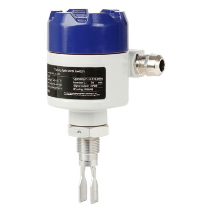
Vibrating level switch
Description
The core element of the vibrating level switch is the vibrating fork with integrated vibration drive. When the vibrating tuning fork is immersed in the medium, the resonance frequency of the tuning fork decreases. The frequency change is detected by the electronic circuit and is converted to a switching signal. Irrespective of the mounting position, level changes can be detected very accurately.
The respective switch point can be changed via a pipe extension. The high switch point accuracy can be individually adjusted to the respective application using ten sensitivity levels. It is also possible to set a switching delay of 1 ... 20 seconds with the model TLS-S. For use in hazardous areas, explosion-protected versions are also available.
For further approvals, see page 5
Vibrating level switch, model TLS
The vibrating level switches are, depending on the version, suitable for an operating temperature of -100 ... +200 °C [-148 ... +392 °F] and an operating pressure of -1 ... +100 bar [-14 ... +1,450 psi]. The vibrating level switch is suitable for media with a density of 500 ... 2,500 g/cm³ [289 ... 1,445 oz/in 3] . The viscosity of the media should be between 0.1 and 10,000 cP [0.24 and 21,190 lb/ft·h].
Special features
- Robust design for the process industry
- Explosion-protected version
- Low maintenance costs
- Stable and reliable level detection, unaffected by flow, bubble formation, vibrations, build-up or solids in the medium
| Model | Description |
|---|---|
| TLS-SA | Vibrating level switch, without Ex |
| TLS-SAD | Vibrating level switch, with Ex d approval |
| Mounting thread | Mounting thread with cooling ele- ment and extension | Flange version | Flange version with cooling element and extension | |
|---|---|---|---|---|
| Connection housing Direction mark Switch point Cooling element Extension | | | | |
| 90 x 125 mm[3.54 x 4.92 in] | ||||
| | ||||
| Connection housing Electrical connection Cable gland | ■ M20 x 1.5 ■ 1/2" NPT ■ 3/4" NPT | |||
| Cable bushing Process connection | ■ M20 x 1.5 ■ 1/2" NPT ■ 3/4" NPT ■ G3/4" ... 2" ■ 3/4 " ....2 " NPT | DN25 ...DN100 per DIN 1" ... 4" per ASME B16.5 | EN 1092-1 | |
| Material | -40 ...+200 °C [-40 ...+392 °F] | |||
| Connection | Aluminium | ■ ■ | ||
| housing Wetted parts | ■ Stainless steel 1.4404 ■ Stainless steel 1.4404, ■ Stainless steel 1.4404 ■ Stainless steel 1.4404 ■ Hastelloy C-276 | (316L) 14435 (316L), electropolished (316L) with PFA coating (316L) with ECTFE coating electropolished °F] | ||
| Ambient temperature Supply voltage Process temperature | ■ Hastelloy C-276, -40 ...+60 °C [-40 ...+140 DC 24V | -40 ...+150 °C [-40 ...+302 °F] | ||
| Density of the medium Operating pressure Switching delay | -40 ...+150 °C | -40 ...+200 °C [-40 ...+392 °F] | ||
| [-40 ...+302 °F] ≥ 500 ... 2,500 kg/m³ | ||||
| ... +1,450 psi] | ||||
| Sensitivity setting Switching output | -1 ...+100 bar [-14.5 1 ... 20 seconds | (adjustable) | ||
| Power consumption Max. switching power Insertion length | 1 ... 10 steps (adjustable) ■ DPDT relay output ■ PNP transistor ■ NAMUR <1W DC 30V / 5 A | [3.0 ... 236.22 in] length - 13 mm[0.51 in] | 60 mm[2.36 in] | |
| (relay output) IP ingress protection Switch point | 76 ...6,000mm | 60 ...6,000mm [2.36 ... 236.22 in] | ||
| calculation Tuning fork length | ||||
| ■ 42 mm[1.65 in] ■ | ||||
| output IP66/68 76 mm[3.0 in] | ||||
| Switch point = insertion | ||||
| 38 mm[1.50 in] |
| Clamp connection | Clamp connection with cooling ele- ment and extension | DIN 11851 food-compliant pro- cess connection | DRD65 food-com- pliant process connection | |
|---|---|---|---|---|
| Connection housing Switch point Cooling element Extension | | | | |
| Connection housing | 90 x 125 mm[3.54 x 4.92 in] | |||
| Electrical connection | ||||
| Cable gland | ■ M20 x 1.5 ■ 1/2" NPT | |||
| Cable bushing | ■ M20 x 1.5 ■ 1/2" NPT ■ 3/4" NPT | |||
| Process connection | 1" ... 4" per ASME BPE | DN20 ...DN100 | DRD65 | |
| Material | ||||
| Connection housing | Aluminium | |||
| Wetted parts | ■ Stainless steel 1.4404 (316L) ■ Stainless steel 1.4404, 14435 (316L), electropolished ■ Stainless steel 1.4404 (316L) with PFA coating ■ Stainless steel 1.4404 (316L) with ECTFE coating ■ Hastelloy C-276 ■ Hastelloy C-276, electropolished | |||
| Ambient temperature | -40 ...+60 °C [-40 ...+140 °F] | |||
| Supply voltage | DC 24V | |||
| Process temperature | -40 ...+150 °C [-40 ...+302 °F] | -40 ...+200 °C [-40 ...+392 °F] | ■ -40 ...+150 °C [-40 ...+302 °F] ■ -40 ...+200 °C [-40 ...+392 °F] with cooling element | ■ -40 ...+150 °C [-40 ...+302 °F] ■ -40 ...+200 °C [-40 ...+392 °F] with cooling element |
| Density of the medium | ≥ 500 ... 2,500 kg/m³ | |||
| Operating pressure | -1 ...+100 bar [-14.5 ... +1,450 psi] | |||
| Switching delay | 1 ... 20 seconds (adjustable) | |||
| Sensitivity setting | 1 ... 10 steps (adjustable) | |||
| Switching output | ■ DPDT relay output ■ PNP transistor output ■ NAMUR (8.2 V) | |||
| Power consumption | <1W | |||
| Max. switching power (relay output) | DC 30V / 5 A | |||
| IP ingress protection | IP66/68 | |||
| Insertion length | ■ 60 mm[2.36 in] ■ 43 mm[1.69 in] ■ 47 mm[1.85 in] | 60 ...6,000mm [2.36 ... 236.22 in] | 60 mm[2.36 in] | 60 ...6,000mm [2.36 ... 236.22 in] |
| Switch point | Switch point = insertion length - 13 mm[0.51 in] | |||
| Tuning fork length | ■ 42 mm[1.65 in] ■ 38 mm[1.50 in] | |||
| Surface roughness (wetted) | ■ Ra ≤ 0.76 μm ■ Ra ≤ 0.38 μm |
| Logo | Description | Region |
|---|---|---|
| EU declaration of conformity 2 1 2 1 2 1 | 2 1 1 2 1 1 2 2 1 1 | European Union |
| EMCdirective EN 61326 emission (group 1, class B) and immunity (industrial environments) RoHS directive UKCA 3 3 3 3 | United Kingdom 3 3 3 3 | 3 |
| Electromagnetic + + + | compatibility regulations Restriction of hazardous substances (RoHS) regulations + + + + | + + |
View all (6)
| Logo | Description | Region | |
|---|---|---|---|
| EU declaration of conformity 4 3 4 3 | European Union 4 | ||
| ATEX directive Hazardous areas 4 3 2 1 4 3 2 1 | |||
| IECEx Hazardous areas - Ex d Zone 1 gas Ex db IIC T6 ...T3 Ga/Gb + + | International | ||
| NEPSI Hazardous areas + + + + | China + + | ||
| - Ex d Zone 1 Zone 1, | gas dust Ex d IIC T3...T6 Gb Ex tb IIIC T85°C ...T200°C Db gas dust Ex ia IIC T3...T6 Ga | ||
| - Ex i Zone 0 Zone 1, | Ex ib IIIC T85°C ...T200°C Db |
| Certificates | ■ 2.2 test report per EN 10204 (e.g. state-of-the-art manufacturing, material proof) ■ 3.1 inspection certificate per EN 10204 (e.g. material proof for wetted metal parts) |
|---|
Couldn't find the answer in the documentation? An engineer will reply within a business day.
Ask an engineer →