
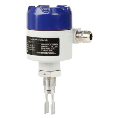
מתג מפלס רוטט
תיאור
האלמנט המרכזי של מתג מפל רטט הוא מזלג רוטט עם כונן רטט משולב. כאשר מזלג הכוונון הרוטט שקוע במדיום, תדירות התהודה של מזלג הכוונון יורדת. שינוי התדירות מזוהה על ידי המעגל האלקטרוני ומומר לאות מיתוג. ללא קשר למיקום ההתקנה, ניתן לזהות שינויים במפל בדיוק רב מאוד.
ניתן לשנות את נקודת המיתוג באמצעות הארכת צינור. דיוק נקודת המיתוג הגבוה ניתן לכוונון פרטני בהתאם ליישום באמצעות עשר רמות רגישות. כמו כן ניתן להגדיר השהיית מיתוג של 1 ... 20 שניות באמצעות הדגם TLS-S. לשימוש באזורים מסוכנים זמינות גם גרסאות מוגנות פיצוץ.
לאישורים נוספים, ראה עמוד 5
מתג מפל רטט, דגם TLS
מתגי מפל רטט מתאימים, בהתאם לגרסה, לטמפרטורת עבודה של -100 ... +200 °C [-148 ... +392 °F] וללחץ עבודה של -1 ... +100 bar [-14 ... +1,450 psi]. מתג מפל רטט מתאים למדיומים בעלי צפיפות של 500 ... 2,500 g/cm³ [289 ... 1,445 oz/in 3]. צמיגות המדיום צריכה להיות בין 0.1 ל-10,000 cP [0.24 ו-21,190 lb/ft·h].
תכונות מיוחדות
- עיצוב עמיד לתעשיית התהליכים
- גרסה מוגנת מפני פיצוץ
- עלויות תחזוקה נמוכות
- זיהוי גובה מילוי יציב ואמין, ללא השפעה של זרימה, היווצרות בועות, רעידות, הצטברות או מוצקים בתווך
שאלות ותשובות
באילו טמפרטורות ולחצים עובד מתג המפלס TLS-S?
בהתאם לגרסה, המתג מתאים לטמפרטורת עבודה של -100 … +200 °C וללחץ עבודה של -1 … +100 bar.
אילו מדיומים המתג מסוגל לנטר?
ה-TLS-S מתאים לכל הנוזלים בעלי צפיפות של 500 … 2,500 g/cm³ וצמיגות של 0.1 … 10,000 cP.
האם קיימת גרסה לאזורים מסוכנים?
כן, זמינות גרסאות מוגנות פיצוץ לשימוש באזורים מסוכנים.
כיצד ניתן לכוונן את נקודת המיתוג?
נקודת המיתוג ניתנת לשינוי באמצעות הארכת צינור, וניתן לכוונן אותה בדיוק רב בהתאם ליישום באמצעות עשר רמות רגישות.
האם ניתן להגדיר השהיית מיתוג?
כן, בדגם TLS-S ניתן להגדיר השהיית מיתוג של 1 … 20 שניות.
האם הזיהוי מושפע מתנאי התהליך?
לא — זיהוי המפלס יציב ואמין ואינו מושפע מזרימה, היווצרות בועות, רעידות, הצטברות משקעים או מוצקים במדיום.
מה מבדיל את ה-TLS-S ממתגי מפלס אחרים?
מזלג הכוונון הרוטט עם כונן הרטט המשולב מאפשר זיהוי מפלס מדויק בכל מיקום התקנה, עם עלויות תחזוקה נמוכות ועיצוב חזק לתעשיית התהליכים.
| Model | Description |
|---|---|
| TLS-SA | Vibrating level switch, without Ex |
| TLS-SAD | Vibrating level switch, with Ex d approval |
| Mounting thread | Mounting thread with cooling ele- ment and extension | Flange version | Flange version with cooling element and extension | |
|---|---|---|---|---|
| Connection housing Direction mark Switch point Cooling element Extension | | | | |
| 90 x 125 mm[3.54 x 4.92 in] | ||||
| | ||||
| Connection housing Electrical connection Cable gland | ■ M20 x 1.5 ■ 1/2" NPT ■ 3/4" NPT | |||
| Cable bushing Process connection | ■ M20 x 1.5 ■ 1/2" NPT ■ 3/4" NPT ■ G3/4" ... 2" ■ 3/4 " ....2 " NPT | DN25 ...DN100 per DIN 1" ... 4" per ASME B16.5 | EN 1092-1 | |
| Material | -40 ...+200 °C [-40 ...+392 °F] | |||
| Connection | Aluminium | ■ ■ | ||
| housing Wetted parts | ■ Stainless steel 1.4404 ■ Stainless steel 1.4404, ■ Stainless steel 1.4404 ■ Stainless steel 1.4404 ■ Hastelloy C-276 | (316L) 14435 (316L), electropolished (316L) with PFA coating (316L) with ECTFE coating electropolished °F] | ||
| Ambient temperature Supply voltage Process temperature | ■ Hastelloy C-276, -40 ...+60 °C [-40 ...+140 DC 24V | -40 ...+150 °C [-40 ...+302 °F] | ||
| Density of the medium Operating pressure Switching delay | -40 ...+150 °C | -40 ...+200 °C [-40 ...+392 °F] | ||
| [-40 ...+302 °F] ≥ 500 ... 2,500 kg/m³ | ||||
| ... +1,450 psi] | ||||
| Sensitivity setting Switching output | -1 ...+100 bar [-14.5 1 ... 20 seconds | (adjustable) | ||
| Power consumption Max. switching power Insertion length | 1 ... 10 steps (adjustable) ■ DPDT relay output ■ PNP transistor ■ NAMUR <1W DC 30V / 5 A | [3.0 ... 236.22 in] length - 13 mm[0.51 in] | 60 mm[2.36 in] | |
| (relay output) IP ingress protection Switch point | 76 ...6,000mm | 60 ...6,000mm [2.36 ... 236.22 in] | ||
| calculation Tuning fork length | ||||
| ■ 42 mm[1.65 in] ■ | ||||
| output IP66/68 76 mm[3.0 in] | ||||
| Switch point = insertion | ||||
| 38 mm[1.50 in] |
| Clamp connection | Clamp connection with cooling ele- ment and extension | DIN 11851 food-compliant pro- cess connection | DRD65 food-com- pliant process connection | |
|---|---|---|---|---|
| Connection housing Switch point Cooling element Extension | | | | |
| Connection housing | 90 x 125 mm[3.54 x 4.92 in] | |||
| Electrical connection | ||||
| Cable gland | ■ M20 x 1.5 ■ 1/2" NPT | |||
| Cable bushing | ■ M20 x 1.5 ■ 1/2" NPT ■ 3/4" NPT | |||
| Process connection | 1" ... 4" per ASME BPE | DN20 ...DN100 | DRD65 | |
| Material | ||||
| Connection housing | Aluminium | |||
| Wetted parts | ■ Stainless steel 1.4404 (316L) ■ Stainless steel 1.4404, 14435 (316L), electropolished ■ Stainless steel 1.4404 (316L) with PFA coating ■ Stainless steel 1.4404 (316L) with ECTFE coating ■ Hastelloy C-276 ■ Hastelloy C-276, electropolished | |||
| Ambient temperature | -40 ...+60 °C [-40 ...+140 °F] | |||
| Supply voltage | DC 24V | |||
| Process temperature | -40 ...+150 °C [-40 ...+302 °F] | -40 ...+200 °C [-40 ...+392 °F] | ■ -40 ...+150 °C [-40 ...+302 °F] ■ -40 ...+200 °C [-40 ...+392 °F] with cooling element | ■ -40 ...+150 °C [-40 ...+302 °F] ■ -40 ...+200 °C [-40 ...+392 °F] with cooling element |
| Density of the medium | ≥ 500 ... 2,500 kg/m³ | |||
| Operating pressure | -1 ...+100 bar [-14.5 ... +1,450 psi] | |||
| Switching delay | 1 ... 20 seconds (adjustable) | |||
| Sensitivity setting | 1 ... 10 steps (adjustable) | |||
| Switching output | ■ DPDT relay output ■ PNP transistor output ■ NAMUR (8.2 V) | |||
| Power consumption | <1W | |||
| Max. switching power (relay output) | DC 30V / 5 A | |||
| IP ingress protection | IP66/68 | |||
| Insertion length | ■ 60 mm[2.36 in] ■ 43 mm[1.69 in] ■ 47 mm[1.85 in] | 60 ...6,000mm [2.36 ... 236.22 in] | 60 mm[2.36 in] | 60 ...6,000mm [2.36 ... 236.22 in] |
| Switch point | Switch point = insertion length - 13 mm[0.51 in] | |||
| Tuning fork length | ■ 42 mm[1.65 in] ■ 38 mm[1.50 in] | |||
| Surface roughness (wetted) | ■ Ra ≤ 0.76 μm ■ Ra ≤ 0.38 μm |
| Logo | Description | Region |
|---|---|---|
| EU declaration of conformity 2 1 2 1 2 1 | 2 1 1 2 1 1 2 2 1 1 | European Union |
| EMCdirective EN 61326 emission (group 1, class B) and immunity (industrial environments) RoHS directive UKCA 3 3 3 3 | United Kingdom 3 3 3 3 | 3 |
| Electromagnetic + + + | compatibility regulations Restriction of hazardous substances (RoHS) regulations + + + + | + + |
הצגת הכול (6)
| Logo | Description | Region | |
|---|---|---|---|
| EU declaration of conformity 4 3 4 3 | European Union 4 | ||
| ATEX directive Hazardous areas 4 3 2 1 4 3 2 1 | |||
| IECEx Hazardous areas - Ex d Zone 1 gas Ex db IIC T6 ...T3 Ga/Gb + + | International | ||
| NEPSI Hazardous areas + + + + | China + + | ||
| - Ex d Zone 1 Zone 1, | gas dust Ex d IIC T3...T6 Gb Ex tb IIIC T85°C ...T200°C Db gas dust Ex ia IIC T3...T6 Ga | ||
| - Ex i Zone 0 Zone 1, | Ex ib IIIC T85°C ...T200°C Db |
| Certificates | ■ 2.2 test report per EN 10204 (e.g. state-of-the-art manufacturing, material proof) ■ 3.1 inspection certificate per EN 10204 (e.g. material proof for wetted metal parts) |
|---|
לא מצאתם תשובה בתיעוד? מהנדס יענה במהלך יום עסקים.
שאלו מהנדס →