
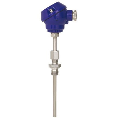
Threaded thermocouple
Description
Thermocouples of this series are used for the measurement of liquid and gaseous media at low and medium pressures.
The thermocouple is screwed directly into the process. The electrical connection is made via connection terminals in the connection head (splash-proof). The measuring inserts are available in two variants, depending upon the application. The choice is between a replaceable, springloaded miniature measuring insert and a non-replaceable, permanently screwed-in design.
for further approvals see page 2
Fig. left: Model TC10-D with process connection compression fitting
Fig. right: Model TC10-D with process connection double threaded hex bushing
Insertion length, process connection and sensor can each be selected for the respective application.
A large number of different explosion-protected approvals are available for the TC10-D.
Special features
- Sensor ranges from -40 ... +600 °C [-40 ... +1,112 °F]
- Compact design
- Universal application
- Direct installation into the process
- Explosion-protected versions are available for many approval types (see data sheet page 2)
Build a TC10-D for your task
The article number is assembled automatically. If unsure — ask an engineer; we'll match the line's parameters.
- Electrical approvalWithout
- Ignition protection typeWithout
- ZoneWithout
- Thermocouple typeType K
- Number of thermocouplesSingle thermocouple
- Accuracy class of the sensorClass 2, IEC 60584
- Validity limits of class accuracy-40…+1200 °C
- Hot junctionUngrounded
- Cable entryStandard cable gland for für A-/B-/J- heads
- Thread size cable entryM16 x 1.5
- TransmitterWithout (terminal block)
- Transmitter detailsWithout
- Connection to neck tubeM10 x 1
- Protection tubeWithout process connection
- Protection tube diameter6 mm
- Protection tube material—
- Process connectionWithout
- Thread sizeWithout
- Material process connectionWithout
- Insertion length [A]—
- Neck length [MH/N]7
- CertificatesWithout
Finish your configuration
Select every option to submit the request.
| Model | TC10-D |
| Product family | TC10 |
| Subcategory | Miniature design |
| Temperature ranges | −40…+600 °C · −40…+1200 °C · −40…+1000 °C · +0…+1260 °C · −40…+750 °C · +0…+760 °C · −40…+900 °C · −40…+800 °C · +0…+870 °C · −40…+350 °C · +0…+370 °C |
| Process connection | M10x1M14x1.5M18x1.5M20x1.5G ¼ BG ⅜ BG ½ B¼ NPT½ NPTCompression fitting with metal ferruleCompression fitting with PTFE ferruleSpring-loaded compression fittingG1/4BG3/8BG1/2B1/4NPT1/2NPTcompression fittingdouble threaded hex bushing |
| Process temperature | −40…+600 °C |
| Output signal | 4-20mA |
| Electrical connection | Connection terminals in connection head |
| Probe material | 1.4571, stainless steel |
| Thermowell material | 1.4571, stainless steel |
| Ambient temperature | −40…+80 °C |
| IP rating | IP65 |
| Certifications | RoHSEMCPESOGOSTKazInMetrMTSCHSBelGIMUkrSEPROUzstandardCE |
| Explosion protection | II 1G Ex ia IIC T1 ... T6 GaII 2G Ex ia IIC T1 ... T6 GbEx ia IIIC T125 ... T65 °C DaII 1D Ex ia IIIC T65 °C DaII 2D Ex ia IIIC T65 °C DbEx iaD 20 T65/T95/T125 °CEx iaD 21 T65/T95/T125 °CZone 1 gas II 2G Ex ia IIC T1 ... T6 GbII 1D Ex ia IIIC T125 ... T65 °C DaII 2D Ex ia IIIC T125 ... T65 °C DbEx ia IIC T1 ... T6 GaEx ia IIC T1 ... T6 GbEx ia IIIC T125 ... T65 °C Db0Ex ia IIC T3/T4/T5/T61Ex ib IIC T3/T4/T5/T6Ex ia IIIC T80 ... T440 °C Da XEx ia IIIC T80 ... T440 °C Db XEx ia IIC T3 ... T6 GaEx ib IIC T3 ... T6 GbEx ib IIIC T125 ... T65 °C DbEx ia IIC T1 ~ T6 GaEx ia IIC T1 ~ T6 GbEx ic IIC T1 ~ T6 GcEx ia IIC T4 ... T6Ex ib IIC T4 ... T6Ex ib IIC T3/T4/T5/T6 GbEx ia IIIC T80...T440 °C DaEx ia IIIC T80...T440 °C DbEx i Zone 0 gas II 1G Ex ia IIC T1 ... T6 GaZone 20 dust II 1D Ex ia IIC T125 ... T65 °C DaZone 21 dust II 2D Ex ia IIC T125 ... T65 °C DbIECEx Ex i Zone 0 gas Ex ia IIC T1 ... T6 GaEx i Zone 1 gas Ex ia IIC T1 ... T6 GbEx i Zone 20 dust Ex ia IIC T125 ... T65 °C DaEx i Zone 21 dust Ex ia IIC T125 ... T65 °C DbEAC Ex i Zone 0 gas 0Ex ia IIC T3/T4/T5/T6Zone 1 gas 1Ex ib IIC T3/T4/T5/T6Zone 20 dust Ex ia IIC T80 ... T440 °C Da XZone 21 dust Ex ia IIC T80 ... T440 °C Db XEx Ukraine Ex i Zone 0 gas II 1G Ex ia IIC T1 ... T6 GaZone 20 dust II 1D Ex ia IIC T65 °C DaZone 21 dust II 2D Ex ia IIC T65 °C DbINMETRO Ex i Zone 0 gas Ex ia IIC T3 ... T6 GaZone 1 gas Ex ib IIC T3 ... T6 GbZone 20 dust Ex ia IIC T125 ... T65 °C DaZone 21 dust Ex ib IIC T125 ... T65 °C DbCCC Ex i Zone 0 gas Ex ia IIC T1 ~ T6 GaZone 1 gas Ex ia IIC T1 ~ T6 GbZone 2 gas Ex ic IIC T1 ~ T6 GcZone 20 dust Ex iaD 20 T65/T95/T125 °CZone 21 dust Ex iaD 21 T65/T95/T125 °CKCs - KOSHA Ex i Zone 0 gas Ex ia IIC T4 ... T6Zone 1 gas Ex ib IIC T4 ... T6PESO Exi Zone0 gas ExiaIICT1...T6GaGOSTKazInMetrMTSCHSBelGIMUkrSEPROUzstandard |
| Sensor type | Type K/J/E/N/T |
| Sensor class | Class 1, Class 2 |
| Probe length | 600 mm |
| Probe diameter | 6 mm |
| Thermowell | Yes |
| Datasheet languages | EN |
| Description | Country | |
|---|---|---|
| EU declaration of conformity ■ EMCdirective 1) | European Union | |
| ■ RoHS directive Hazardous areas - Ex i Zone 0 gas Ex ia IIC T1 ...T6 | Ga | |
| Zone 1 gas 1Ex ib IIC T3/T4/T5/T6 Zone 20 dust Ex ia IIIC T80 ...T440 °C Da X Zone 21 dust Ex ia IIIC T80 ...T440 °C Db X Ex Ukraine (option) Hazardous areas - Ex i Zone 0 gas II 1G Ex ia IIC T1 ...T6 Ga Zone 1 gas | ||
| IECEx (option) - in conjunction with ATEX | International | |
| Zone 20 dust Zone 21 dust INMETRO (option) Hazardous areas Ex i Zone 0 gas | II 2G Ex ia IIC T1 ...T6 Gb II 1D Ex ia IIIC T65 °C Da II 2D Ex ia IIIC T65 °C Db | Ukraine |
| - Zone 1 gas | Ex ia IIC T3 ...T6 Ga Ex ib IIC T3 ...T6 Gb Ex ia IIIC T125 ...T65 °C Da Ex ib IIIC T125 ...T65 °C Db | Brazil |
| - | ||
| Zone 20 dust Zone 21 dust CCC (option) 2) Hazardous areas Ex i Zone 0 gas | Ex ia IIC T1 ~ T6 Ga Ex ia IIC T1 ~ T6 Gb Ex ic IIC T1 ~ T6 Gc | |
| Zone 1 gas Zone 2 gas Zone 20 dust Zone 21 dust | Ex iaD 20 T65/T95/T125 °C Ex iaD 21 T65/T95/T125 °C | China |
| - KOSHA (option) areas i | Ex ia IIC T4 ...T6 | |
| South Korea | ||
| Zone 0 gas | ||
| Ex ib IIC T4 ...T6 | ||
| 1 gas | ||
| Zone | ||
| KCs Hazardous - Ex |
| Logo | Description | Country |
|---|---|---|
| - | PESO (option) Hazardous areas - Ex i Zone 0 gas Ex ia IIC T1 Zone 1 gas Ex ib IIC T3 | India |
| GOST (option) Metrology, measurement technology | Russia | |
| KazInMetr (option) Metrology, measurement technology | Kazakhstan | |
| - | MTSCHS (option) Permission for commissioning | Kazakhstan |
| BelGIM (option) Metrology, measurement technology | Belarus | |
| UkrSEPRO (option) Metrology, measurement technology | Ukraine | |
| Uzstandard (option) Metrology, measurement technology | Uzbekistan |
| Type | Validity limits of class accuracy | ||
|---|---|---|---|
| IEC 60584-1 | ASTM E230 | ||
| Class 2 | Class 1 | Standard Special | |
| K | -40 ... +1,200 °C | -40 ... +1,000 °C | 0 ... 1,260 °C |
| J | -40 ...+750 °C | -40 ...+750 °C | 0 ... 760 °C |
| E | -40 ...+900 °C | -40 ...+800 °C | 0 ... 870 °C |
| N | -40 ... +1,200 °C | -40 ... +1,000 °C | 0 ... 1,260 °C |
| T | -40 ...+350 °C | 0 ... 370 °C |
| Cable entry | Cable entry thread size | Min./max. ambient temperature |
|---|---|---|
| Standard cable entry | M16 x 1.5 | -40 ...+80 °C |
| Plastic cable gland | M16 x 1.5 | -40 ...+80 °C |
| Plastic cable gland, Ex e | M16 x 1.5 | -20 ...+80 °C (standard) -40 ...+70 °C (option) |
| Brass cable gland, nickel-plated | M16 x 1.5 | -40 ...+80 °C |
View all (12)
| Cable entry | Colour | Ingress protection | Explosion protection | |
|---|---|---|---|---|
| (max.) IEC/EN 60529 1) | without | Ex i (gas), zone 0, 1, 2 | ||
| Standard cable entry | Blank | IP65 | x | x |
| Plastic cable gland | Black or grey | IP65 | x | - |
| Plastic cable gland, Ex e | Light blue | IP65 | x | x |
| Plastic cable gland, Ex e | Black | IP65 | x | - |
| Brass cable gland, nickel-plated | Blank | IP65 | x | - |
| Brass cable gland, nickel-plated, Ex e | Blank | IP65 | x | x |
| First index number | Degree of protection / short description | Test parameter |
|---|---|---|
| 5 | Dust-protected | per IEC/EN 60529 |
| 6 | Dust-tight | per IEC/EN 60529 |
| Second index number | Degree of protection / short description | Test parameter |
|---|---|---|
| 4 | Protected against splash water | per IEC/EN 60529 |
| 5 | Protected against water jets | per IEC/EN 60529 |
| Transmitter (selectable versions) | Model T91.20 |
|---|---|
| Data sheet | TE 91.01 |
| Output | |
| 4 ...20mA | x |
| Ausgang | |
| Thermocouples IEC 60584-1 | K, J,T |
| Explosion protection | - |
| Connection head | T91.20 |
|---|---|
| JS | ○ |
| Diameter | Process connection | Thread size | Neck length (standard) | Max. neck length | Min. insertion length | Max. insertion length | Material |
|---|---|---|---|---|---|---|---|
| N (M H ) | N (M H ) | A (U 1 ) / A (U 2 ) A | (U 1 ) / A (U 2 ) | ||||
| 6mm 8mm | without | - | 7mm (hexagonal height) | 7mm (hexagonal height) | 50mm | 600mm | 1.4571 |
| Double threaded hex bushing (male thread directly on the connection head) | G¼B G⅜B G½B M10 x 1 1) M14 x 1.5 M18 x 1.5 M20 x 1.5 | 10mm (hexagonal height incl. dimension up to the screw-in plane) | 10mm (hexagonal height incl. dimension up to the screw-in plane) | ||||
| ¼NPT ½NPT | approx.19mm (hexagonal height incl. dimension up to the screw-in plane) | approx.19mm (hexagonal height incl. dimension up to the screw-in plane) | |||||
| Male thread (offset-welded to thermowell) | G¼B G⅜B G½B M10 x 1 1) M14 x 1.5 M18 x 1.5 M20 x 1.5 | 55mm | 200mm | 50mm | 600 mm(incl. neck length) | ||
| Compression fitting with metal ferrule Compression fitting with PTFE ferrule 2) | ½NPT G¼B G⅜B G½B M10 x 1 1) | approx.55mm | |||||
| Spring-loaded compression fitting | ¼NPT ½NPT G¼B G⅜B G½B M14 x 1.5 M18 x 1.5 M20 x 1.5 | approx.100mm |
| Removable design | Fixed design | |
|---|---|---|
| Description | The measuring insert is spring-mounted with two screws into the connection head and can simply be removed from the thermowell for calibration purposes.The thermowell itself can thus remain in the process.The terminal block for electrical connection is connected to the probe tube of the measuring insert. | There is no removable measuring insert in this version. Instead, the sensor element is mounted directly in the thermowell tip.The terminal base for the electrical connection is permanently screwed into the connection head. |
| Diameter (for thermowellØ=6mm) | 3mm | - |
| Diameter (for thermowellØ=8mm) | 6mm | - |
| Operating temperatures (dependent upon the sensor design type and the accuracy class) | Min: -40 °C Max: +600 °C | Min: -40 °C Max: +250 °C |
| Built-in measuring insert model | TC10-A | - |
| Certification type | Measurement accuracy | Material certificate |
|---|---|---|
| 2.2 test report | x | x |
| 3.1 inspection certificate | x | x |
| DKD/DAkkS calibration certificate | x | - |
Couldn't find the answer in the documentation? An engineer will reply within a business day.
Ask an engineer →6 standard articles of family TC10
If you know the code — pick directly. If not — use the configurator in mode “01”.