
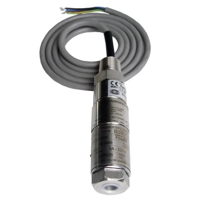
Miniature pressure switch, stainless steel
Description
These high-quality mechanical pressure switches have been developed especially for safety-critical applications. The great advantage of mechanical pressure switches is that no supply voltage is required for the switching process.
In production, the switches are traced by quality assurance software at every step and subsequently are 100 % tested. Due to its compactness, the model PXS pressure switch can be installed in measurement environments with limited space. The robust switch enclosure from stainless steel 316 can withstand the rough and corrosive operating conditions of the process industry with working ranges of up to 1,000 bar.
for further approvals, see page 5
Special features
- Compact and slimline design
- Robust switch enclosure from stainless steel 316, IP66, NEMA 4X
- Wide selection of setting ranges available, 1 … 2.5 bar to 200 … 1,000 bar
- Set point repeatability of ≤ 1 % for reliable switching
- High switching power and large selection of contact variants and electrical connections
| Model | PXS |
| Product family | Process Mini Series |
| Subcategory | Mechanical pressure switch |
| Pressure ranges | 1…2.5 bar · 200…1000 bar · 1.6…6 bar · 2…6 bar · 3…10 bar · 6…25 bar · 14…60 bar · 25…100 bar · 50…160 bar · 70…400 bar · 150…700 bar · -1…1.5 bar |
| Accuracy class | ≤ 1 % of end of setting range |
| Accuracy standard | IEC 61298-2:2008 |
| Safety integrity level (SIL) | SIL 2 qualified, SIL 3 qualified |
| Process connection | ¼ NPT, female thread½ NPT, female thread via adapter½ NPT, male thread via adapterG ¼, female thread via adapterG ½ A, male thread via adapterG ¼ A, male thread via adapter1/4 NPT, female thread1/2 NPT, female thread via adapter1/2 NPT, male thread via adapterG1/4, female thread via adapterG1/2A, male thread via adapterG1/4A, male thread via adapter |
| Process temperature | −40…+200 °C |
| Electrical connection | Threaded connection with connection cable (½ NPT male, M20 x 1.5, ½ NPT female, ¾ NPT female), Terminal box with 3 x ½ NPT female, IP65 |
| Switching function | Adjustable set point with dead band depending on setting range |
| Switching contacts | 1 |
| Case material | Stainless steel 316 |
| Wetted parts material | Hastelloy C276, Stainless steel 316L |
| Sealing material | FPM, NBR, EPDM |
| Ambient temperature | −30…+85 °C |
| IP rating | IP66 |
| Weight | 0.6 kg |
| Certifications | CERoHSNACE MR0175 / ISO 15156NACE MR0103 / ISO 17945 |
| Explosion protection | Ex ia IIIC T85°C/T135°C Da IP66ATEX I M1 II 1 GDIECEx Ex ia I MaEx ia IIC T6/T4 GaEx ia I Ma Ex ia IIC T6/T4 Ga Ex ia IIIC T85°C/T135°C Da IP66Ex ia I MaEx ia IIIC T6/T4 GaEACExATEX |
| Datasheet languages | EN |
| Version | Miniature pressure switch |
|---|---|
| Special design feature | ■ Version for hazardous areas (Ex ia) ■ For oxygen, oil- and grease-free ■ Per NACE 1) MR0175 / ISO 15156, use in H₂S-containing environments in oil and gas production ■ Per NACE 1) MR0103 / ISO 17945, metals resistant to sulphide stress cracking ■ Drying of wetted parts ■ Offshore version ■ Tropical version (suitable for environments with increased air humidity) ■ Version for ammonia applications ■ Geothermal version ■ Assembled as a diaphragm seal system |
| Contact version | ■ 1 x SPDT (single pole double throw) ■ 1 x DPDT (double pole double throw) Microswitch, hermetically sealed, with fixed dead band The DPDT function is realised with 2 simultaneously triggering SPDT microswitches. →See table 'Contact version' |
| Dielectric strength | Safety class I (IEC 61298-2: 2008) |
| Switch enclosure | |
| Design | Tamper-proof due to access cover plate with lead seal option Laser-engraved product label from stainless steel |
| Material | Stainless steel 316 |
| Mounting | ■ Direct mounting ■ Wall bracket from stainless steel ■ Mounting bracket for 2" pipe mounting |
| Contact version | Electrical rating (resistive load) | ||
|---|---|---|---|
| AC | DC | ||
| E | 1 x SPDT, silver, hermetically sealed | 250 V, 5 A | 24 V, 5 A |
| J | 1 x SPDT, gold-plated, hermetically sealed | 250 V, 0.5 A | 24 V, 1 A |
| L | 1 x DPDT, silver, hermetically sealed | 250 V, 5 A | 24 V, 5 A |
| M | 1 x DPDT, gold-plated, hermetically sealed | 250 V, 0.5 A | 24 V, 1 A |
| Sensor element | Wetted parts | Permissible medium temperature 1) | ||
|---|---|---|---|---|
| Sensor element | Sealing | |||
| M | 1 = Welded diaphragm element with antagonist spring | Hastelloy C276 | - | -40 ...+200 °C |
| 2 = Diaphragm element with antagonist spring and O-ring | Hastelloy C276 | O-ring:FPM | -30 ...+200 °C | |
| G | Piston with antagonist spring and welded diaphragm element | Hastelloy C276 | - | -40 ...+140 °C |
| P | Piston with antagonist spring 2) 3) | Stainless steel 316L | O-ring:FPM | 0 ... 200 °C |
| O-ring:NBR | -10 ...+110 °C | |||
| O-ring:EPDM | -40 ...+110 °C |
| Set point repeatability | ≤ 1 %of end of setting range |
|---|---|
| Dead band | →See table 'Setting range of set point' |
View all (13)
| Setting range of set point | Sensor element | Setting range depending on the switching direction in bar | Working range | Proof pressure | Max. dead band | ||
|---|---|---|---|---|---|---|---|
| in bar | rising | falling | in bar | in bar | Start of setting range 4) in bar | End of setting range 4) in bar | |
| -1 ... 1.5 | M 5) | -0.7 ... 1.5 | -0.9 ... 1.2 | -1 ... 10 | 40 | 0.3 | 0.3 |
| 1 ... 2.5 6) | M 5) | 1.3 ... 2.5 | 1 ... 2.2 | 0 ... 10 | 16 | 0.3 | 0.3 |
| 1.6 ... 6 | M 5) | 2.1 ... 6 | 1.6 ... 5.8 | 0 ... 10 | 16 | 0.5 | 0.2 |
| 2 ... 6 | M 7) | 2.5 ... 6 | 2 ... 5.8 | 0 ... 207 | 315 | 0.5 | 0.2 |
| 3 ... 10 | M 7) | 4.5 ... 10 | 3 ... 9.2 | 0 ... 207 | 315 | 1.5 | 0.8 |
| 3 ... 10 | M 5) | 4.5 ... 10 | 3 ... 9.2 | 0 ... 10 | 16 | 1.5 | 0.8 |
| 6 ... 25 6) | M 5) | 8 ... 25 | 6 ... 24.2 | 0 ... 25 | 40 | 2 | 0.8 |
| 6 ... 25 | M 7) | 8 ... 25 | 6 ... 24.2 | 0 ... 207 | 315 | 2 | 0.8 |
| 14 ... 60 | P,G | 23 ... 60 | 14 ... 49 | 0 ... 500 | 750 | 9 | 11 |
| 25 ... 100 | P,G | 40 ... 100 | 25 ... 82 | 0 ... 500 | 750 | 15 | 18 |
| 50 ... 160 | P,G | 65 ... 160 | 50 ... 142 | 0 ... 500 | 750 | 15 | 18 |
| 70 ... 400 | P,G | 95 ... 400 | 70 ... 365 | 0 ... 500 | 750 | 25 | 35 |
| 150 ... 700 8) | P | 230 ... 700 | 150 ... 600 | 0 ... 1,000 | 1,500 | 80 | 100 |
| 200 ... 1,000 8) | P | 300 ... 1,000 | 200 ... 850 | 0 ... 1,000 | 1,500 | 100 | 150 |
| Process connection | |
|---|---|
| Standard | ■ ANSI/ASME B1.20.1 ■ DIN EN ISO 228 |
| Size | |
| ANSI/ASME B1.20.1 | ■ ¼NPT, female thread ■ ½NPT, female thread via adapter ■ ½NPT, male thread via adapter |
| DIN EN ISO 228 | ■ G¼, female thread via adapter ■ G½A,male thread via adapter ■ G¼A,male thread via adapter |
| Material (wetted) | |
| Process connection | Stainless steel 316L |
| Other materials on request | |
| Sensor element | Depending on the selected sensor element →See table 'Sensor element' |
| Connection type | ■ Threaded connection with connection cable, ½NPTmale thread ■ Threaded connection with connection cable, M20 x 1.5 via adapter ■ Threaded connection with connection cable, ½NPTfemale thread via adapter ■ Threaded connection with connection cable, ¾NPTfemale thread via adapter ■ Terminal box, 3 x female thread ½NPT, IP65 |
|---|---|
| Wire cross-section | 0.5 mm² (20 AWG) |
| Cable length | |
| Threaded connection with connection cable | ■ 1.5m ■ 3m ■ 5m |
| Terminal box | - |
| Pin assignment | Connection details are given on the product label of the instrument. Connec- tion terminals and the ground terminal are appropriately marked. |
| Material | |
| Threaded connection with connection cable | Threaded connection: Stainless steel 316 Cable sheath: Silicone |
| Terminal box | Aluminium alloy, copper-free, epoxy resin coated |
| Medium temperature range | Ex version 1) | T M -30 ...+60 °C |
|---|---|---|
| Other versions | →See table 'Sensor element' | |
| Ambient temperature range | T6/T85°C | T a -30 ...+60 °C |
| T4/T135°C | T a -30 ...+85 °C | |
| Other versions | T a -30 ...+85 °C | |
| Ingress protection of the complete instrument | IP66 per EN/IEC 60529 (NEMA 4X) | |
| Weight | ■ 0.6 kg, with cable outlet and 1.5 mconnection cable ■ 1.1 kg, with terminal box |
| Description | Region |
|---|---|
| EU declaration of conformity | European Union |
| Pressure equipment directive | |
| EMCdirective | |
| Low voltage directive | |
| RoHS directive |
| Logo | Description | Region |
|---|---|---|
| EU declaration of conformity | European Union | |
| IECEx 1) Ex ia I Ma Ex ia IIC T6/T4 2) Ga Ex ia IIIC T85°C/T135°C 2) Da IP66 | International | |
| EAC EMCdirective | Eurasian Economic Community | |
| Pressure equipment directive | ||
| Low voltage directive | ||
| Hazardous areas 1) | ||
| Ex Ukraine Hazardous areas 1) | Ukraine | |
| CCC Hazardous areas 1) | China | |
| KOSHA Hazardous areas 1) | South Korea |
| Certificates | ■ 2.2 test report per EN 10204 (e.g. state-of-the-art manufacturing, indication accuracy) ■ 3.1 inspection certificate per EN 10204 (e.g. indication accuracy) |
|---|---|
| Recommended recalibration interval | 1 year (dependent on conditions of use) |
| Voltage | Ui = DC 30V |
|---|---|
| Current | Ii = 100mA |
| Power | P i = 750mW |
| Effective internal capacitance | Ci ≤ 0 μF |
| Effective internal inductance | Li=0mH |
| Model | Description | |
|---|---|---|
| 910.15 | Syphons →see data sheet AC 09.06 | |
| 910.13 | Overpressure protector →see data sheet AC 09.04 | |
| IV10, IV11 | Needle valve and multiport valve →see data sheet AC 09.22 | |
| IV20, IV21 | Block-and-bleed valve →see data sheet AC 09.19 | |
| IVM | Monoflange, process and instrument version →see data sheet AC 09.17 | |
| BV | Ball valve, process and instrument version →see data sheet AC 09.28 |
Couldn't find the answer in the documentation? An engineer will reply within a business day.
Ask an engineer →