
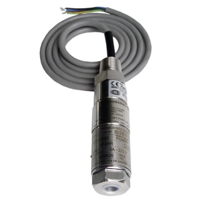
מתג לחץ זעיר, נירוסטה
תיאור
מתגי לחץ מכניים באיכות גבוהה אלה פותחו במיוחד עבור יישומים בעלי חשיבות בטיחותית. היתרון הגדול של מתגי לחץ מכניים הוא שבמהלך תהליך ההפעלה אין צורך במתח אספקה.
בייצור, המתגים עוברים עקיבה באמצעות תוכנת בקרת איכות בכל שלב ולאחר מכן נבדקים ב-100%. בשל קומפקטיותו, ניתן להתקין את מתג הלחץ מדגם PXS בסביבות מדידה שבהן יש מקום מוגבל. בית המתג העמיד ממתכת אל-חלד 316 יכול לעמוד בתנאי עבודה קשים ומאכלים של תעשיית התהליכים, עם טווחי עבודה של עד 1,000 bar.
ללא אישורים נוספים, ראה עמוד 5
תכונות מיוחדות
- עיצוב קומפקטי ודק
- בית מפסק עמיד מפלדת אל-חלד 316, IP66, NEMA 4X
- מבחר רחב של טווחי כיול זמינים, 1 … 2.5 bar ועד 200 … 1,000 bar
- חזרנות נקודת מיתוג של ≤ 1 % למיתוג אמין
- הספק מיתוג גבוה ומבחר רחב של וריאנטי מגעים וחיבורים חשמליים
שאלות ותשובות
מהו טווח הלחץ של מתג ה-PXS?
קיים מבחר רחב של טווחי כיוון, מ-1 … 2.5 bar ועד 200 … 1,000 bar, וכן טווח ואקום/לחץ של -1 … 1.5 bar.
מהי הדיוק של המתג?
חזרתיות נקודת ההפעלה היא ≤ 1 % מקצה טווח הכיוון, בהתאם לתקן IEC 61298-2:2008.
אילו חיבורי תהליך זמינים?
¼ NPT נקבי כחיבור סטנדרטי; באמצעות מתאם זמינים גם ½ NPT נקבי או זכרי, G ¼ נקבי, ו-G ¼ A או G ½ A זכרי.
מאילו חומרים עשויים החלקים במגע עם התווך?
Hastelloy C276 או Stainless steel 316L, עם אטימה מ-FPM, NBR או EPDM — מה שמאפשר שימוש בתווך אגרסיבי, צמיג מאוד או מזוהם.
מהם טווחי הטמפרטורה המותרים?
טמפרטורת סביבה: -30 … +85 °C; טמפרטורת תווך: -40 … +200 °C.
האם ה-PXS מאושר לאזורים מסוכנים?
כן: ATEX I M1 II 1 GD, IECEx Ex ia I Ma, Ex ia IIC T6/T4 Ga ו-Ex ia IIIC T85°C/T135°C Da IP66, וכן EACEx. בנוסף, המתג מוסמך SIL 2 qualified, SIL 3 qualified.
האם המתג דורש מתח אספקה?
לא. מדובר במתג לחץ מכני, ויתרונו הגדול הוא שאין צורך במתח אספקה במהלך ההפעלה.
מה מבדיל את ה-PXS מדגמים אחרים?
העיצוב הקומפקטי והדק מאפשר התקנה בנקודות מדידה עם מקום מוגבל, כגון לוחות בקרה, והמארז מפלדת אל-חלד 316 עם IP66/NEMA 4X עמיד בתנאי עבודה קשים ומאכלים.
| דגם | PXS |
| סדרה | Process Mini Series |
| תת-קטגוריה | Mechanical pressure switch |
| טווח לחץ | 1…2.5 bar · 200…1000 bar · 1.6…6 bar · 2…6 bar · 3…10 bar · 6…25 bar · 14…60 bar · 25…100 bar · 50…160 bar · 70…400 bar · 150…700 bar · -1…1.5 bar |
| מחלקת דיוק | ≤ 1 % of end of setting range |
| תקן דיוק | IEC 61298-2:2008 |
| רמת בטיחות תפקודית (SIL) | SIL 2 qualified, SIL 3 qualified |
| חיבור תהליך | ¼ NPT, female thread½ NPT, female thread via adapter½ NPT, male thread via adapterG ¼, female thread via adapterG ½ A, male thread via adapterG ¼ A, male thread via adapter1/4 NPT, female thread1/2 NPT, female thread via adapter1/2 NPT, male thread via adapterG1/4, female thread via adapterG1/2A, male thread via adapterG1/4A, male thread via adapter |
| טמפ׳ תהליך | −40…+200 °C |
| חיבור חשמלי | Threaded connection with connection cable (½ NPT male, M20 x 1.5, ½ NPT female, ¾ NPT female), Terminal box with 3 x ½ NPT female, IP65 |
| פונקציית מתג | Adjustable set point with dead band depending on setting range |
| מגעי מתג | 1 |
| חומר מארז | Stainless steel 316 |
| חומר חלקים רטובים | Hastelloy C276, Stainless steel 316L |
| חומר אטם | FPM, NBR, EPDM |
| טמפ׳ סביבה | −30…+85 °C |
| דרגת הגנה IP | IP66 |
| משקל | 0.6 kg |
| תקנים | CERoHSNACE MR0175 / ISO 15156NACE MR0103 / ISO 17945 |
| הגנת התפוצצות | Ex ia IIIC T85°C/T135°C Da IP66ATEX I M1 II 1 GDIECEx Ex ia I MaEx ia IIC T6/T4 GaEx ia I Ma Ex ia IIC T6/T4 Ga Ex ia IIIC T85°C/T135°C Da IP66Ex ia I MaEx ia IIIC T6/T4 GaEACExATEX |
| שפות גיליון נתונים | EN |
| Version | Miniature pressure switch |
|---|---|
| Special design feature | ■ Version for hazardous areas (Ex ia) ■ For oxygen, oil- and grease-free ■ Per NACE 1) MR0175 / ISO 15156, use in H₂S-containing environments in oil and gas production ■ Per NACE 1) MR0103 / ISO 17945, metals resistant to sulphide stress cracking ■ Drying of wetted parts ■ Offshore version ■ Tropical version (suitable for environments with increased air humidity) ■ Version for ammonia applications ■ Geothermal version ■ Assembled as a diaphragm seal system |
| Contact version | ■ 1 x SPDT (single pole double throw) ■ 1 x DPDT (double pole double throw) Microswitch, hermetically sealed, with fixed dead band The DPDT function is realised with 2 simultaneously triggering SPDT microswitches. →See table 'Contact version' |
| Dielectric strength | Safety class I (IEC 61298-2: 2008) |
| Switch enclosure | |
| Design | Tamper-proof due to access cover plate with lead seal option Laser-engraved product label from stainless steel |
| Material | Stainless steel 316 |
| Mounting | ■ Direct mounting ■ Wall bracket from stainless steel ■ Mounting bracket for 2" pipe mounting |
| Contact version | Electrical rating (resistive load) | ||
|---|---|---|---|
| AC | DC | ||
| E | 1 x SPDT, silver, hermetically sealed | 250 V, 5 A | 24 V, 5 A |
| J | 1 x SPDT, gold-plated, hermetically sealed | 250 V, 0.5 A | 24 V, 1 A |
| L | 1 x DPDT, silver, hermetically sealed | 250 V, 5 A | 24 V, 5 A |
| M | 1 x DPDT, gold-plated, hermetically sealed | 250 V, 0.5 A | 24 V, 1 A |
| Sensor element | Wetted parts | Permissible medium temperature 1) | ||
|---|---|---|---|---|
| Sensor element | Sealing | |||
| M | 1 = Welded diaphragm element with antagonist spring | Hastelloy C276 | - | -40 ...+200 °C |
| 2 = Diaphragm element with antagonist spring and O-ring | Hastelloy C276 | O-ring:FPM | -30 ...+200 °C | |
| G | Piston with antagonist spring and welded diaphragm element | Hastelloy C276 | - | -40 ...+140 °C |
| P | Piston with antagonist spring 2) 3) | Stainless steel 316L | O-ring:FPM | 0 ... 200 °C |
| O-ring:NBR | -10 ...+110 °C | |||
| O-ring:EPDM | -40 ...+110 °C |
| Set point repeatability | ≤ 1 %of end of setting range |
|---|---|
| Dead band | →See table 'Setting range of set point' |
הצגת הכול (13)
| Setting range of set point | Sensor element | Setting range depending on the switching direction in bar | Working range | Proof pressure | Max. dead band | ||
|---|---|---|---|---|---|---|---|
| in bar | rising | falling | in bar | in bar | Start of setting range 4) in bar | End of setting range 4) in bar | |
| -1 ... 1.5 | M 5) | -0.7 ... 1.5 | -0.9 ... 1.2 | -1 ... 10 | 40 | 0.3 | 0.3 |
| 1 ... 2.5 6) | M 5) | 1.3 ... 2.5 | 1 ... 2.2 | 0 ... 10 | 16 | 0.3 | 0.3 |
| 1.6 ... 6 | M 5) | 2.1 ... 6 | 1.6 ... 5.8 | 0 ... 10 | 16 | 0.5 | 0.2 |
| 2 ... 6 | M 7) | 2.5 ... 6 | 2 ... 5.8 | 0 ... 207 | 315 | 0.5 | 0.2 |
| 3 ... 10 | M 7) | 4.5 ... 10 | 3 ... 9.2 | 0 ... 207 | 315 | 1.5 | 0.8 |
| 3 ... 10 | M 5) | 4.5 ... 10 | 3 ... 9.2 | 0 ... 10 | 16 | 1.5 | 0.8 |
| 6 ... 25 6) | M 5) | 8 ... 25 | 6 ... 24.2 | 0 ... 25 | 40 | 2 | 0.8 |
| 6 ... 25 | M 7) | 8 ... 25 | 6 ... 24.2 | 0 ... 207 | 315 | 2 | 0.8 |
| 14 ... 60 | P,G | 23 ... 60 | 14 ... 49 | 0 ... 500 | 750 | 9 | 11 |
| 25 ... 100 | P,G | 40 ... 100 | 25 ... 82 | 0 ... 500 | 750 | 15 | 18 |
| 50 ... 160 | P,G | 65 ... 160 | 50 ... 142 | 0 ... 500 | 750 | 15 | 18 |
| 70 ... 400 | P,G | 95 ... 400 | 70 ... 365 | 0 ... 500 | 750 | 25 | 35 |
| 150 ... 700 8) | P | 230 ... 700 | 150 ... 600 | 0 ... 1,000 | 1,500 | 80 | 100 |
| 200 ... 1,000 8) | P | 300 ... 1,000 | 200 ... 850 | 0 ... 1,000 | 1,500 | 100 | 150 |
| Process connection | |
|---|---|
| Standard | ■ ANSI/ASME B1.20.1 ■ DIN EN ISO 228 |
| Size | |
| ANSI/ASME B1.20.1 | ■ ¼NPT, female thread ■ ½NPT, female thread via adapter ■ ½NPT, male thread via adapter |
| DIN EN ISO 228 | ■ G¼, female thread via adapter ■ G½A,male thread via adapter ■ G¼A,male thread via adapter |
| Material (wetted) | |
| Process connection | Stainless steel 316L |
| Other materials on request | |
| Sensor element | Depending on the selected sensor element →See table 'Sensor element' |
| Connection type | ■ Threaded connection with connection cable, ½NPTmale thread ■ Threaded connection with connection cable, M20 x 1.5 via adapter ■ Threaded connection with connection cable, ½NPTfemale thread via adapter ■ Threaded connection with connection cable, ¾NPTfemale thread via adapter ■ Terminal box, 3 x female thread ½NPT, IP65 |
|---|---|
| Wire cross-section | 0.5 mm² (20 AWG) |
| Cable length | |
| Threaded connection with connection cable | ■ 1.5m ■ 3m ■ 5m |
| Terminal box | - |
| Pin assignment | Connection details are given on the product label of the instrument. Connec- tion terminals and the ground terminal are appropriately marked. |
| Material | |
| Threaded connection with connection cable | Threaded connection: Stainless steel 316 Cable sheath: Silicone |
| Terminal box | Aluminium alloy, copper-free, epoxy resin coated |
| Medium temperature range | Ex version 1) | T M -30 ...+60 °C |
|---|---|---|
| Other versions | →See table 'Sensor element' | |
| Ambient temperature range | T6/T85°C | T a -30 ...+60 °C |
| T4/T135°C | T a -30 ...+85 °C | |
| Other versions | T a -30 ...+85 °C | |
| Ingress protection of the complete instrument | IP66 per EN/IEC 60529 (NEMA 4X) | |
| Weight | ■ 0.6 kg, with cable outlet and 1.5 mconnection cable ■ 1.1 kg, with terminal box |
| Description | Region |
|---|---|
| EU declaration of conformity | European Union |
| Pressure equipment directive | |
| EMCdirective | |
| Low voltage directive | |
| RoHS directive |
| Logo | Description | Region |
|---|---|---|
| EU declaration of conformity | European Union | |
| IECEx 1) Ex ia I Ma Ex ia IIC T6/T4 2) Ga Ex ia IIIC T85°C/T135°C 2) Da IP66 | International | |
| EAC EMCdirective | Eurasian Economic Community | |
| Pressure equipment directive | ||
| Low voltage directive | ||
| Hazardous areas 1) | ||
| Ex Ukraine Hazardous areas 1) | Ukraine | |
| CCC Hazardous areas 1) | China | |
| KOSHA Hazardous areas 1) | South Korea |
| Certificates | ■ 2.2 test report per EN 10204 (e.g. state-of-the-art manufacturing, indication accuracy) ■ 3.1 inspection certificate per EN 10204 (e.g. indication accuracy) |
|---|---|
| Recommended recalibration interval | 1 year (dependent on conditions of use) |
| Voltage | Ui = DC 30V |
|---|---|
| Current | Ii = 100mA |
| Power | P i = 750mW |
| Effective internal capacitance | Ci ≤ 0 μF |
| Effective internal inductance | Li=0mH |
| Model | Description | |
|---|---|---|
| 910.15 | Syphons →see data sheet AC 09.06 | |
| 910.13 | Overpressure protector →see data sheet AC 09.04 | |
| IV10, IV11 | Needle valve and multiport valve →see data sheet AC 09.22 | |
| IV20, IV21 | Block-and-bleed valve →see data sheet AC 09.19 | |
| IVM | Monoflange, process and instrument version →see data sheet AC 09.17 | |
| BV | Ball valve, process and instrument version →see data sheet AC 09.28 |
לא מצאתם תשובה בתיעוד? מהנדס יענה במהלך יום עסקים.
שאלו מהנדס →