
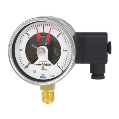
Bourdon tube pressure gauge with switch contacts
Description
Wherever the process pressure has to be indicated locally and, at the same time, circuits need to be switched, the model PGS21.1x0 switchGAUGE finds its use.
Switch contacts (electrical alarm contacts) make or break circuits dependent upon the pointer position of the indicating measuring instrument. The switch contacts are adjustable over the full extent of the scale range (see DIN 16085), and are mounted predominantly below the dial, though also partly on top of the dial. The instrument pointer (actual value pointer) moves freely across the entire scale range, independent of the setting.
The set pointer can be adjusted using a removable adjustment key in the window.
For further approvals see page 7
Model PGS21.100 with model 821.21 switch contacts
Switch contacts consisting of several contacts can also be set to a single set point. Contact actuation is made when the actual value pointer travels beyond or below the desired set point.
The pressure gauge is manufactured in accordance with DIN 16085 and fulfils all requirements of the relevant standards (EN 837-1) and regulations for the on-site display of the working pressure of pressure vessels.
As switch contacts, magnetic snap-action contacts, reed switches and electronic contacts are available. For triggering programmable logic controllers (PLC), electronic contacts and reed switches can be used.
Special features
- High reliability and long service life
- Up to 3 switch contacts per instrument
- Instruments with electronic contacts for PLC applications
- Contact gauges comply with DIN 16085
| Model | PGS21.100 |
| Product family | PGS21 |
| Subcategory | Switch contact pressure gauge |
| Pressure ranges | 0…0.6 bar · 0…600 bar |
| Accuracy class | 1.0 |
| Accuracy standard | EN 837-1 |
| Process connection | M20 x 1.5G ½ B½ NPTG1/2B1/2NPT |
| Process temperature | −20…+80 °C |
| Output signal | PNP transistor |
| Power supply | DC 10 ... 30 V |
| Electrical connection | Cable socket PA 6, black Per VDE 0110 insulation group C/250 V, Cable gland M20 x 1.5, 6 screw terminals + PE |
| Switching function | Normally open (clockwise pointer motion), Normally closed (clockwise pointer motion), Change-over |
| Switching contacts | 3 |
| Case material | Stainless steel |
| Wetted parts material | Copper alloy, Stainless steel 316L |
| Ambient temperature | −20…+60 °C |
| IP rating | IP54 |
| Certifications | CEEU declaration of conformity |
| Dial size | 100 mm |
| Datasheet languages | EN |
| Standard version | |
|---|---|
| Nominal size inmm | ■ 100 ■ 160 |
| Accuracy class | 1.0 |
| Scale ranges | 0 ... 0.6 bar [0 ... 8.7 psi] to 0 ... 600 bar [0 ... 8,702.26 psi] other units (e.g. psi, kPa) available or all other equivalent vacuum or combined pressure and vacuum ranges |
| Scale | ■ Single scale ■ Dual scale |
| Pressure limitation | |
| Steady | Full scale value |
| Fluctuating | 0.9 x full scale value |
| Short time | 1.3 x full scale value |
| Connection location | ■ Lower mount (radial) ■ Lower back mount |
| Process connection (copper alloy) | ■ G½B ■ ½NPT ■ M20 x 1.5 others on request |
| Permissible temperature | |
| Medium | +80 °C [+176 °F] Higher medium temperature on request |
| Ambient | -20 ...+60 °C [-4 ...+140 °F] |
| Temperature effect | When the temperature of the measuring system deviates from the reference temperature (+20 °C): max. ±0.4 %/10 K of full scale value |
| Case | Stainless steel |
| Case filling | Without |
| Wetted materials | |
| Process connection, pressure element | < 100 bar: Copper alloy, trumpet form ≥ 100 bar: Stainless steel 316L, helical type |
| Non-wetted materials | |
| Case, bayonet ring | Stainless steel |
| Movement | Copper alloy, wear parts argentan |
| Dial | Aluminium, white, black lettering |
| Instrument pointer | Aluminium, black |
| Set pointer | Aluminium, red |
| Window | ■ Polycarbonate ■ Laminated safety glass |
| Ingress protection per IEC/EN 60529 | IP54 |
| Electrical connection | Cable socket PA 6, black PerVDE 0110 insulation group C/250V Cable gland M20 x 1.5 Strain relief 6 screw terminals + PE for conductor cross-section 2.5 mm² For dimensions see page 9 others on request |
| Measuring span | Nominal size | Max. number of contacts | Switching current range I | Switch version 1) |
|---|---|---|---|---|
| ≤ 1.0 bar | 100, 160 | 1 | 0.02 ... 0.3 A | L |
| > 1.0 bar | 100, 160 | 1 | 0.02 ... 0.6 A | S |
| ≤ 1.6 bar | 100, 160 | 2 | 0.02 ... 0.3 A | L |
| > 1.6 bar | 100, 160 | 2 | 0.02 ... 0.6 A | S |
| ≤ 4.0 bar | 100 | 3 | 0.02 ... 0.3 A | L |
| > 4.0 bar | 100 | 3 | 0.02 ... 0.6 A | S |
| ≤ 2.5 bar | 160 | 3 | 0.02 ... 0.3 A | L |
| > 2.5 bar | 160 | 3 | 0.02 ... 0.6 A | S |
| Characteristics | Unfilled instruments | Filled instruments | ||
|---|---|---|---|---|
| Resistive load | Resistive load | |||
| Switch version 'S' | Switch version 'L' | Switch version 'S' | Switch version 'L' | |
| Rated operating voltage U eff | ≤ 250V | ≤ 250V | ||
| Rated operating current | ||||
| Switch-on current | ≤ 1.0 A | ≤ 0.5 A | ≤ 1.0 A | ≤ 0.5 A |
| Switch-off current | ≤ 1.0 A | ≤ 0.5 A | ≤ 1.0 A | ≤ 0.5 A |
| Continuous current | ≤ 0.6 A | ≤ 0.3 A | ≤ 0.6 A | ≤ 0.3 A |
| Switching power | ≤ 30W/ ≤ 50VA | ≤ 20W/ ≤ 20VA |
| Operating voltage | Unfilled instruments | Filled instruments | ||||
|---|---|---|---|---|---|---|
| Resistive load | Inductive load | Resistive load | Inductive load | |||
| Direct current | Alter- nating current | cos ϕ>0.7 | Direct current | Alter- nating current | cos ϕ>0.7 | |
| DC 220 V / AC 230 V | 100mA | 120mA | 65mA | 65mA | 90mA | 40mA |
| DC 110 V / AC 110 V | 200mA | 240mA | 130mA | 130mA | 180mA | 85mA |
| DC 48 V / AC 48 V | 300mA | 450mA | 200mA | 190mA | 330mA | 130mA |
| DC 24 V / AC 24 V | 400mA | 600mA | 250mA | 250mA | 450mA | 150mA |
View all (19)
| Measuring span | Nominal size | Max. number of contacts |
|---|---|---|
| 0.6 bar | 100, 160 | 1 |
| 1.0 bar | 100, 160 | 2 |
| ≥ 1.6 bar | 100, 160 | 2 |
| Contact version | Normally open, normally closed |
|---|---|
| Type of output | PNP transistor |
| Operating voltage | DC 10 ...30V |
| Residual ripple | max.10% |
| No-load current | ≤ 10mA |
| Switching current | ≤ 100mA |
| Residual current | ≤ 100 µA |
| Voltage drop (with I max. ) | ≤ 0.7V |
| Reverse polarity protection | Conditional U B (the switched output 3 or 4 must never be set directly to minus) |
| Anti-inductive protection | 1 kV, 0.1 ms, 1 kΩ |
| Oscillator frequency | approx. 1,000 kHz |
| EMC | per EN 60947-5-2 |
| Measuring span | Nominal size | Max. number of contacts |
|---|---|---|
| ≥ 1.0 bar | 100, 160 | 1 |
| ≥ 1.6 bar | 100, 160 | 2 |
| Characteristics | |
|---|---|
| Contact version | Change-over contact |
| Type of contact | Bistable |
| Max. switching voltage | AC/DC 250V |
| Min. switching voltage | Not required |
| Switching current | AC/DC 1 A |
| Min. switching current | Not required |
| Transport current | AC/DC 2 A |
| cosϕ | 1 |
| Switching power | 60W/VA |
| Contact resistance (static) | 100mΩ |
| Insulation resistance | 10 9 Ω |
| Breakdown voltage | DC 1,000V |
| Switching time incl. contact chatter | 4.5 ms |
| Contact material | Rhodium |
| Switch hysteresis | 3 ...5% |
| Logo | Description | Region |
|---|---|---|
| EU declaration of conformity | European Union |
| Certificates | ■ 2.2 test report per EN 10204 (e.g. state-of-the-art manufacturing, indication accuracy) ■ 3.1 inspection certificate per EN 10204 (e.g. material proof for wetted metal parts, indi - cation accuracy, calibration certificate) |
|---|---|
| Recommended calibration interval | 1 year (dependent on conditions of use) |
| Type of contact | Dimensions inmm | Process connection | Dimensions inmm | ||||||
|---|---|---|---|---|---|---|---|---|---|
| X | Y | h ±1 | S2 | S3 | S4 | S5 | S6 | ||
| Single or double contact | 88 | 55 | G½B | 87 | 6 | 20 | 3 | 17 | 17.5 |
| Double (change-over) contact | 113 | 80 | G ¼ B | 80 | 5 | 13 | 2 | 11 | 9.5 |
| Triple contact | 96 | 63 | G⅜B | 83 | 5.5 | 16 | 3 | 14 | 13 |
| Quadruple contact | 113 | 80 | ½NPT | 86 | - | 19 | - | - | - |
| Process connection | Dimensions inmm | |||||
|---|---|---|---|---|---|---|
| b | S2 | S3 | S4 | S5 | S6 | |
| G½B | 33.5 | 6 | 20 | 3 | 17 | 17.5 |
| G ¼ B | 26.5 | 5 | 13 | 2 | 11 | 9.5 |
| G⅜B | 29.5 | 5.5 | 16 | 3 | 14 | 13 |
| ½NPT | 32.5 | - | 19 | - | - | - |
| Type of contact | Dimensions inmm | |
|---|---|---|
| X | Y | |
| Single or double contact | 88 | 55 |
| Triple contact | 96 | 63 |
| Quadruple contact | 113 | 80 |
| Process connection | Dimensions inmm | |||||
|---|---|---|---|---|---|---|
| h ±1 | S2 | S3 | S4 | S5 | S6 | |
| G½B | 118 | 6 | 20 | 3 | 17 | 17.5 |
| G ¼ B | 111 | 5 | 13 | 2 | 11 | 9.5 |
| G⅜B | 114 | 5.5 | 16 | 3 | 14 | 13 |
| ½NPT | 117 | - | 19 | - | - | - |
| Type of contact | Dimensions inmm X |
|---|---|
| Single or double contact | 105 |
| Triple contact | 105 |
| Quadruple contact | 119 |
| Process connection | Dimensions inmm | |||||
|---|---|---|---|---|---|---|
| b | S2 | S3 | S4 | S5 | S6 | |
| G½B | 33.5 | 6 | 20 | 3 | 17 | 17.5 |
| G ¼ B | 26.5 | 5 | 13 | 2 | 11 | 9.5 |
| G⅜B | 29.5 | 5.5 | 16 | 3 | 14 | 13 |
| ½NPT | 32.5 | - | 19 | - | - | - |
| Process connection | Dimensions inmm | |||||
|---|---|---|---|---|---|---|
| h ±1 | S2 | S3 | S4 | S5 | S6 | |
| G½B | 87 | 6 | 20 | 3 | 17 | 17.5 |
| G ¼ B | 80 | 5 | 13 | 2 | 11 | 9.5 |
| G⅜B | 83 | 5.5 | 16 | 3 | 14 | 13 |
| ½NPT | 86 | - | 19 | - | - | - |
| Process connection | Dimensions inmm | |||||
|---|---|---|---|---|---|---|
| h ±1 | S2 | S3 | S4 | S5 | S6 | |
| G½B | 103 | 6 | 20 | 3 | 17 | 17.5 |
| G ¼ B | 96 | 5 | 13 | 2 | 11 | 9.5 |
| G⅜B | 99 | 5.5 | 16 | 3 | 14 | 13 |
| ½NPT | 102 | - | 19 | - | - | - |
| Process connection | Dimensions inmm | |||||
|---|---|---|---|---|---|---|
| h ±1 | S2 | S3 | S4 | S5 | S6 | |
| G½B | 118 | 6 | 20 | 3 | 17 | 17.5 |
| G ¼ B | 111 | 5 | 13 | 2 | 11 | 9.5 |
| G⅜B | 114 | 5.5 | 16 | 3 | 14 | 13 |
| ½NPT | 117 | - | 19 | - | - | - |
Couldn't find the answer in the documentation? An engineer will reply within a business day.
Ask an engineer →1 standard articles of family PGS21
If you know the code — pick directly. If not — use the configurator in mode “01”.