
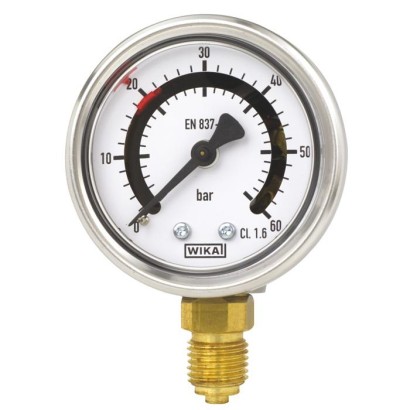
Bourdon tube pressure gauge with switch contacts
Description
The model PGS21 switchGAUGE is a combination of a Bourdon tube pressure gauge and either one or two switch contacts. It offers the usual analogue indication, which can be read on-site irrespective of the power supply, and in addition the possibility to switch a potential-free electrical signal.
One or two switch points are factory-set to customer requirements, fixed between 10 and 90 % of the scale range, and indicated on the dial by red mark pointers. Depending on the pointer position, the circuit will be opened or closed. Thus the switchGAUGE can be used actively for process monitoring, for example to monitor the level of a gas cylinder or a hydraulic circuit.
For further approvals, see page 8
Special features
- High switching reliability and long service life
- With up to two magnetic snap-action contacts or one reed switch
- Set points fixed to customer requirements
- Increased ingress protection, IP65
- Scale ranges from 0 ... 2.5 to 0 ... 400 bar [0 ... 60 to 0 ... 6,000 psi]
| Model | PGS21.040 |
| Product family | PGS21 |
| Subcategory | Pressure gauge with switch contacts |
| Pressure ranges | 0…2.5 bar · 0…4 bar · 0…6 bar · 0…10 bar · 0…16 bar · 0…25 bar · 0…40 bar · 0…0.25 MPa · 0…0.4 MPa · 0…0.6 MPa · 0…1 MPa · 0…1.6 MPa · 0…2.5 MPa · -0.6…0 bar · -1…0 bar · -1…0.6 bar · -1…1.5 bar · -1…3 bar · -100…0 kPa · -100…60 kPa · -100…150 kPa · -100…300 kPa · -0.06…0 MPa · -0.1…0 MPa · -0.1…0.06 MPa · -0.1…0.15 MPa · -0.1…0.3 MPa · 0…60 psi · 0…100 psi · 0…160 psi · 0…400 psi · 0…600 psi · -30…0 inHg · 0…250 kPa · 0…400 kPa · 0…600 kPa · 0…1000 kPa · 0…1600 kPa · 0…2500 kPa · -60…0 kPa · 0…1000 psi · 0…1500 psi · 0…2000 psi · 0…3000 psi · 0…4000 psi · 0…5000 psi · 0…6000 psi · 0…4 MPa · 0…6 MPa · 0…10 MPa · 0…16 MPa · 0…25 MPa · 0…40 MPa · -100…500 kPa · -100…900 kPa · -100…2400 kPa · -0.1…0.5 MPa · -0.1…0.9 MPa · -0.1…1.5 MPa · -0.1…2.4 MPa · 0…200 psi · 0…300 psi · 0…800 psi · 0…2.5 kg/cm² · 0…4 kg/cm² · 0…6 kg/cm² · 0…10 kg/cm² · 0…16 kg/cm² · 0…25 kg/cm² · -30…15 inHg · -30…30 inHg · -30…60 inHg · 0…60 bar · 0…100 bar · 0…160 bar · 0…400 bar · 0…4000 kPa · 0…6000 kPa · 0…10000 kPa · 0…16000 kPa · 0…25000 kPa · 0…40000 kPa · 0…40 kg/cm² · 0…60 kg/cm² · 0…100 kg/cm² · 0…160 kg/cm² · 0…250 kg/cm² · 0…400 kg/cm² |
| Accuracy class | 2.5 |
| Accuracy standard | EN 837-1 |
| Process connection | G ⅛ BG ¼ BM10 x 1⅛ NPT¼ NPTR ⅛R ¼G 1/8 B, male threadG 1/4 B, male threadM10 x 1, male thread1/8 NPT, male thread1/4 NPT, male threadR 1/8, male threadR 1/4, male thread |
| Process temperature | −40…+60 °C |
| Output signal | Magnetic snap-action contact · Reed switch |
| Electrical connection | Cable outlet, PUR cable, 1 m |
| Switching function | 1 normally open (NO), 1 normally closed (NC), change-over |
| Switching contacts | 2 |
| Case material | Stainless steel 1.4301 (304) |
| Wetted parts material | Copper alloy |
| Ambient temperature | −20…+60 °C |
| IP rating | IP65 |
| Certifications | RoHSCE |
| Dial size | 40 mm |
| Datasheet languages | EN |
| bar | |
|---|---|
| 0 ... 2.5 | 0 ... 60 |
| 0 ... 4 | 0 ... 100 |
| 0 ... 6 | 0 ... 160 |
| 0 ... 10 | 0 ... 250 |
| 0 ... 16 | 0 ... 315 |
| 0 ... 25 | 0 ... 400 |
| 0 ... 40 | - |
| psi | |
|---|---|
| 0 ... 60 | 0 ... 1,000 |
| 0 ... 100 | 0 ... 1,500 |
| 0 ... 160 | 0 ... 2,000 |
| 0 ... 200 | 0 ... 3,000 |
| 0 ... 300 | 0 ... 4,000 |
| 0 ... 400 | 0 ... 5,000 |
| 0 ... 600 | 0 ... 6,000 |
| 0 ... 800 | - |
| kPa | |
|---|---|
| 0 ... 250 | 0 ... 4,000 |
| 0 ... 400 | 0 ... 6,000 |
| 0 ... 600 | 0 ... 10,000 |
| 0 ... 1,000 | 0 ... 16,000 |
| 0 ... 1,600 | 0 ... 25,000 |
| 0 ... 2,500 | 0 ... 40,000 |
| bar | |
|---|---|
| -0.6 ... 0 | -1 ...+5 |
| -1 ... 0 | -1 ...+9 |
| -1 ... +0.6 | -1 ...+15 |
| -1 ... +1.5 | -1 ...+24 |
| -1 ...+3 | - |
View all (20)
| -30 inHg ... 0 | -30 inHg ...+100 |
|---|---|
| -30 inHg ...+15 | -30 inHg ...+160 |
| -30 inHg ...+30 | -30 inHg ...+200 |
| -30 inHg ...+60 | -30 inHg ...+300 |
| kg/cm 2 | |
|---|---|
| 0 ... 2.5 | 0 ... 40 |
| 0 ... 4 | 0 ... 60 |
| 0 ... 6 | 0 ... 100 |
| 0 ... 10 | 0 ... 160 |
| 0 ... 16 | 0 ... 250 |
| 0 ... 25 | 0 ... 400 |
| 0 ... 0.25 | 0 ... 4 |
|---|---|
| 0 ... 0.4 | 0 ... 6 |
| 0 ... 0.6 | 0 ... 10 |
| 0 ... 1 | 0 ... 16 |
| 0 ... 1.6 | 0 ... 25 |
| 0 ... 2.5 | 0 ... 40 |
| -60 ... 0 | -100 ...+500 |
|---|---|
| -100 ... 0 | -100 ...+900 |
| -100 ...+60 | -100 ... +1,500 |
| -100 ...+150 | -100 ... +2,400 |
| -100 ...+300 | - |
| -0.06 ... 0 | -0.1 ... +0.5 |
|---|---|
| -0.1 ... 0 | -0.1 ... +0.9 |
| -0.1 ... +0.06 | -0.1 ... +1.5 |
| -0.1 ... +0.15 | -0.1 ... +2.4 |
| -0.1 ... +0.3 | - |
| Type of contact | Magnetic snap-action contact |
|---|---|
| Number of switch contacts | |
| NS 40 [1 ½"], NS 63 [2 ½"] | 1 contact |
| NS 50 [2"] | ■ 1 contact ■ 2 contacts |
| Switching function | →See table 'Switching function' |
| Switch point setting | Set pointer factory-set, fixed within scale range |
| Setting range (recommended) | 10 ... 90 %of span (0 ... 100 %onrequest) |
| Distance between switch points | With a version with 2 contacts, these must not be set to the same point.The re- quired distance is approx. 15 %of the span. |
| Switching current | 5 ...100mA |
| Switching voltage | DC / AC 4.5 ...24V |
| Switching power | ≤ 2.4W |
| Switching function Magnetic snap-action contact | Index | Symbol | Setting direction | Code |
|---|---|---|---|---|
| 1 normally open (NO) | 1 | Contact makes with clockwise pointer motion | 1 | |
| Contact makes with anticlockwise pointer motion | 5 | |||
| 1 normally closed (NC) | 2 | Contact breaks with clockwise pointer motion | 2 | |
| Contact breaks with anticlockwise pointer motion | 4 | |||
| 1 normally open + 1 normally closed | 12 | For setting directions of the switching functions, see NOor NC | - | |
| 1 normally closed + 1 normally open | 21 | For setting directions of the switching functions, see NOor NC | - | |
| 2 normally open | 11 | For setting directions of the switching functions, see NOor NC | - | |
| 2 normally closed | 22 | For setting directions of the switching functions, see NOor NC | - |
| Connection type | IP code 1) | Wire cross-section | Cable diameter | Cable material |
|---|---|---|---|---|
| Cable outlet | ||||
| Unshielded | IP67 | 3 x 0.14 mm² | 4mm | PUR |
| Angular connector DIN 175301-803 C | ||||
| With mating connector | IP65 | To max. 0.75 mm² | 4.5 ...6mm | - |
| Circular connector M12 x 1 (4-pin) | ||||
| Without mating connector | IP67 | - | - | - |
| Circular connector M8 x 1 (3-pin) | ||||
| Without mating connector | IP67 | - | - | - |
| Type of contact | Bistable reed switch |
|---|---|
| Number of switch contacts | 1 switch contact |
| Switching function | →See table 'Switching function' |
| Switch point setting | Factory-set, fixed within scale range (red mark on the dial) |
| Setting range (recommended) | 10 ... 90 %of span |
| Switch hysteresis | <4% |
| Switching current | ≤ AC/DC 0.5 A |
| Switching voltage | ≤ AC/DC 48V |
| Switching power | ≤ 5 W, 5VA |
| Contact resistance (static) | 150mΩ |
| Insulation resistance | 10 9 Ω |
| Breakdown voltage | DC 200V |
| Switching time incl. contact bounce | 4.5 ms |
| Switching function Reed switch, model 851 | Index | Setting direction |
|---|---|---|
| Normally open (NO) | 1 | Contact makes with clockwise pointer motion |
| Normally closed (NC) | 2 | Contact breaks with clockwise pointer motion |
| Change-over | 3 | One contact breaks and one contact makes simultaneously when pointer reaches set point |
| 1 contact | 2 contacts | |
|---|---|---|
| U B | Red | Red |
| SP1 | Black | Orange |
| SP2 | - | Black |
| Circular connector M12 x | 1 contact | 2 contacts | |
|---|---|---|---|
| U B | 1 | 1 | |
| SP1 | 4 | 4 | |
| SP2 | - | 2 |
| 1 contact | 2 contacts | ||
|---|---|---|---|
| U B | 1 | 1 | |
| SP1 | 2 | 2 | |
| SP2 | - | 3 |
| 1 contact | 2 contacts | ||
|---|---|---|---|
| U B | 1 | 1 | |
| SP1 | 4 | 4 | |
| SP2 | - | 3 |
| Medium temperature range | ≤ +60 °C [+140 °F] |
|---|---|
| Ambient temperature range | -20 ...+60 °C [-4 ...+140 °F] |
| Storage temperature range | -40 ...+70 °C [-40 ...+158 °F] |
| Pressure limitation | |
| Steady | 3/4 x full scale value |
| Fluctuating | 2/3 x full scale value |
| Ingress protection per IEC/EN 60529 | IP65 |
| Logo | Description | Region |
|---|---|---|
| EU declaration of conformity | European Union | |
| RoHS directive |
Couldn't find the answer in the documentation? An engineer will reply within a business day.
Ask an engineer →1 standard articles of family PGS21
If you know the code — pick directly. If not — use the configurator in mode “01”.