
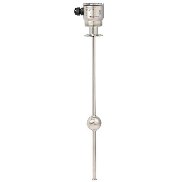
Reed level transmitter
Description
The model FLR level transmitters with reed measuring chain are used for level measurement in liquid media. They work on the float principle with magnetic transmission.
The float's magnetic system in the guide tube actuates a resistance measuring chain that corresponds to a 3-wire potentiometer circuit. The measurement voltage generated by this is proportional to the fill level.
The measurement voltage is very finely stepped due to the contact separation of the measuring chain and is thus virtually continuous. Depending on the requirements several different contact separations are available.
Reed level transmitter, model FLR-F
Special features
- Process- and procedure-specific solutions possible
- Operating temperature: T = -80 ... +200 °C [-112 ... +392 °F]
- Operating pressure: P = Vacuum to 25 bar [362.6 psi]
- Limit density: ρ ≥ 400 kg/m 3 [25.0 lbs/ft 3 ]
- Wide variety of different electrical connections, process connections and materials
- Optionally with programmable and configurable head-mounted transmitter for 4 ... 20 mA field signals, HART ® , PROFIBUS ® PA and FOUNDATION™ Fieldbus
- Explosion-protected versions (option)
| Model | FLR-F |
| Product family | FLR |
| Subcategory | Reed level transmitter |
| Level ranges | 1.5…6 m |
| Process connection | ISO 2852, DN 25 ... DN 150DIN 11851 threaded pipe connection DN 50...DN 150DIN 32676 clamp pipe connection DN 25...DN 100ISO 2852 clamp pipe connection DN 25...DN 150DIN 11851, downwards, DN 50 ... DN 150DIN 32676, DN 25 … DN100 or 1" … 4"DIN 11851, DN 50 ... DN 150DIN 32676, DN 25 ... DN 100 |
| Process temperature | −80…+200 °C |
| Max process pressure | 25 bar |
| Measurement technology | float |
| Output signal | 3-wire potentiometer · 4...20 mA · HART · PROFIBUS PA · FOUNDATION Fieldbus |
| Power supply | < AC 50 V, < DC 75 V |
| Electrical connection | Aluminium 80 x 75 x 57 mm connection housing, options: Polyester, stainless steel |
| Wetted parts material | Stainless steel 1.4435 (316L), Stainless steel 1.4404 (316L), Stainless steel 1.4435 (36L), Stainless steel 1.4404 (36L) |
| Ambient temperature | −20…+120 °C |
| IP rating | IP66/IP68 |
| Certifications | RoHS directiveEMC EN 61326RoHSATEXEC 1935/2004EMC directive EN 61326EC regulation no. 1935/2004CEEMC directive |
| Explosion protection | Ex i II 1/2G Ex ia IIC T4...T6 Ga/Gb or II 2D Ex ib IIIC T80 °C DbEx d II 2G Ex d IIC T6 Gb / II 2 D Ex tb IIIC T80 °C DbEx i II 1/2G Ex ia IIC T4 ...T6 Ga/Gb or II 2D Ex ib IIIC T80 °C Db No.KEMA 01 ATEX 1052Ex d II 2G Ex d IIC T6 Gb / II 2 D Ex tb IIIC T80 °C Db No.TÜV 13 ATEX 7399 XEx i II 1/2G Ex ia IIC T4 ...T6 Ga/Gb or No. KEMA 01 ATEX 1052 XII 2D Ex ib IIIC T80 °C DbEx d II 2G Ex d IIIC T6 Gb / II 2D Ex tb IIIC T80 °C Db No.TÜV 13 ATEX 7399 X |
| Datasheet languages | EN |
| Level transmitter | Description |
|---|---|
| FLR-FA | Version without head-mounted transmitter |
| FLR-FB | Version with head-mounted transmitter |
| Logo | Description | Country |
|---|---|---|
| EU declaration of conformity ■ EMCdirective EN 61326 emission (group 1, class B) and immunity (industrial application) ■ RoHS directive | European Union | |
| ■ ATEX directive (option) Hazardous areas - Ex i II 1/2G Ex ia IIC T4 ...T6 Ga/Gb or II 2D Ex ib IIIC T80 °C Db No.KEMA 01 ATEX 1052 - Ex d II 2G Ex d IIC T6 Gb / II 2 D Ex tb IIIC T80 °C Db No.TÜV 13 ATEX 7399 X |
| Model FLR-FA | Model FLR-FB | |
|---|---|---|
| Electrical connection | Connection housing: Aluminium 80 x 75 x 57 mm[3.1 x 3.0 x 2.2 in] without head-mounted transmitter Option: Polyester, stainless steel | Connection housing: Aluminium 80 x 75x57mm [3.1 x 3.0 x 2.2 in] with head-mounted transmitter Option: Polyester, stainless steel |
| Material (process connection, guide tube, float) | ■ Stainless steel 1.4435 (316L) ■ Stainless steel 1.4404 (316L) Electropolished surface | |
| Process connection | ■ Threaded pipe connection DIN 11851, downwards, DN 50 ...DN 150 ■ Clamp pipe connection DIN 32676, DN 25 …DN100or 1" …4" ■ Clamp pipe connection ISO 2852, DN 25 ...DN 150 Others on request | |
| Guide tube diameter | ■ 12 mm[0.5 in] ■ 14 mm[0.6 in] ■ 18 mm[0.7 in] | |
| Max. guide tube length L | ■ 1,500 mm(guide tube diameter 12 mm[0.5 in]) ■ 3,500 mm(guide tube diameter 14 mm[0.6 in]) ■ 6,000 mm(guide tube diameter 18 mm[0.7 in]) | |
| Float diameter | 44 ... 120 mm[1.7 ... 4.7 in] | |
| Float selection | Depending on guide tube diameter and process conditions | (see page 5) |
| Max. operating pressure | See page 5 | |
| Temperature range | -20 ...+120 °C [-4 ...+248 °F] Option: ■ High-temperature version: 120 ... 200 °C [248 ... ■ Low-temperature version: -80 ... -20 °C [-112 ... -4 | 392 °F] °F] |
| Contact separation | ■ 5 mm[0.2 in] ■ 10 mm[0.4 in] ■ 15 mm[0.6 in] ■ 18 mm[0.7 in] | |
| Resolution | ■ 2.7 mm[0.1 in] ■ 5.5 mm[0.2 in] ■ 7.5 mm[0.3 in] ■ 9 mm[0.4 in] 1) (depending on contact separation) | |
| Overall resistance of the measuring chain | Depending on length and separation | |
| Head-mounted transmitter | External transmitter | Head-mounted transmitter, see page 6 |
| Tube end | ■ Float limitation welded to guide tube ■ Float limitation removable (with FDA conform sealing per CFR21 Food and Drugs for guide tube diameters 12 mm[0.5 in] and 14 mm[0.6 in]) | |
| Output | 3-wire potentiometer | 4 ...20mA |
| Connection cable to transmitter/ control room | Cable length max. 2,000 m, 3-wire, shielded | 2-wire, shielded |
| Permissible supply voltage | < AC 50V < DC 75V | See the data sheet of the head-mounted transmitter used |
| Mounting position | Vertical ±30° | |
| Ingress protection | Up to IP66 or IP68 per IEC/EN 60529 (depending on version) |
| Material | Version | Suits guide tube Ø in mm[in] | Ø A inmm [in] | B inmm [in] | Ø C inmm [in] | Max. operating pressure in bar [psi] | Max. operating temp. in °C [°F] | Limit density 85 %in kg/m 3 [lbs/ft³] |
|---|---|---|---|---|---|---|---|---|
| 1.4404 or 1.4571 | VE52R | ■ 12 [0.5] ■ 14 [0.6] | 52 [2.0] | 52 [2.0] | 15 [0.6] | 25 [362.6] | 250 [482] | 700 [43.7] |
| VE62R | ■ 12 [0.5] ■ 14 [0.6] | 62 [2.4] | 61 [2.4] | 15 [0.6] | 16 [232.1] | 250 [482] | 597 [37.3] | |
| VE80R | 18 [0.7] | 80 [3.1] | 76 [2.9] | 23 [0.9] | 16 [232.1] | 250 [482] | 617 [38.5] | |
| VE83R | ■ 12 [0.5] ■ 14 [0.6] | 83 [3.3] | 81 [3.2] | 15 [0.6] | 16 [232.1] | 250 [482] | 412 [25.7] | |
| VE98R | 18 [0.7] | 98 [3.9] | 96 [3.8] | 23 [0.9] | 16 [232.1] | 250 [482] | 561 [35.0] | |
| VE105R | 18 [0.7] | 105 [4.1] | 103 [4.1] | 23 [0.9] | 16 [232.1] | 250 [482] | 520 [32.5] | |
| VE120R | 18 [0.7] | 120 [4.7] | 117 [4.6] | 23 [0.9] | 16 [232.1] | 250 [482] | 394 [24.6] |
View all (6)
| Material | Version | Suits guide tube Ø in mm[in] | Ø A inmm [in] | B inmm [in] | Ø C inmm [in] | Max. operating pressure in bar [psi] | Max. operating temp. in °C [°F] | Limit density 85 %in kg/m 3 [lbs/ft³] |
|---|---|---|---|---|---|---|---|---|
| 1.4404 or 1.4571 | VE44R | ■ 12 [0.5] ■ 14 [0.6] | 44 [1.7] | 52 [2.0] | 15 [0.6] | 16 [232.1] | 250 [482] | 740 [46.2] |
| Model | 4 ... 20 mA | HART ® | PROFIBUS ® PA | FOUNDATION™ Fieldbus | Ex i | Order umber |
|---|---|---|---|---|---|---|
| TE | x | - | - | - | x | 014832 |
| TS | x | - | - | - | - | 005894 |
| T32E | x | x | - | - | x | 025216 |
| T32S | x | x | - | - | - | 114795 |
| T53F | - | - | - | x | x | 025727 |
| T53P | - | - | x | - | x | 034422 |
| T15 | x | - | - | - | x | 122955 122954 |
Couldn't find the answer in the documentation? An engineer will reply within a business day.
Ask an engineer →1 standard articles of family FLR
If you know the code — pick directly. If not — use the configurator in mode “01”.