
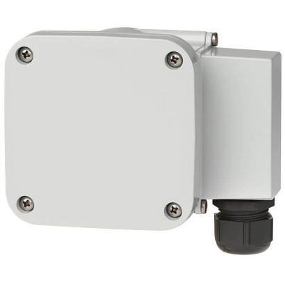
WIKA · SF6 gas solutions · Family GDS
Gas density switch
Gas density switch with reference chamber for monitoring SF6 gas density in high-voltage equipment, featuring temperature compensation and self-diagnostics.
Range
0…12.5 bar
Protection
IP65/IP67
CERoHS
Price
On request
Depends on configuration
Special features
- Accurate isochore, temperature-compensated switching over the entire temperature range
- Increased plant safety through self-diagnostics
- Prepared for any alternative gases
- Very high long-term stability through welded reference gas volume
Identification
| Model | GDS-RC-HV |
| Product family | GDS |
| Subcategory | Gas density switch with reference chamber |
Measuring range
| Pressure ranges | 0…10 bar · 0…12.5 bar |
| Density reference temperature | 20 °C |
Process conditions
| Process connection | G 1/2 B per EN 837, axial or radial |
Electrical characteristics
| Switching contacts | 4 |
Materials
| Wetted parts material | Stainless steel |
Operating environment
| Ambient temperature | −40…+80 °C |
| IP rating | IP65/IP67 |
| Weight | 1.25 kg |
Certifications and approvals
| Certifications | CERoHS |
Additional details
| Temperature compensation | Yes |
| Datasheet languages | EN |
Tables from datasheet
General
| Measurement principle | Reference gas measurement |
|---|---|
| Measuring range | ■ 0 ... 10 bar abs. at 20 °C [68 °F] SF₆ gas ■ 0 ... 12.5 bar abs. at 20 °C [68 °F] SF₆ gas |
| Self-indication in case of malfunc- tion | Integrated into the instrument, the switch contact is actuated in case of leakage in the reference chamber |
| Product label | Lasered onto the reference chamber, maximum weather resistance |
Accuracy
| Switching accuracy | |
|---|---|
| -1 ...+5 bar at 20 °C [68 °F] | ■ ±70 mbar at calibration pressure at 20 °C [68 °F], gaseous phase ■ ±100 mbar at calibration pressure at -30 …+50 °C [-22 ...+122 °F], gaseous phase |
| -1 ...+9 bar at 20 °C [68 °F] | ■ ±100 mbar at calibration pressure at 20 °C [68 °F], gaseous phase ■ ±150 mbar at calibration pressure at -30 …+50 °C [-22 ...+122 °F], gaseous phase |
| -1 ... +11.5 bar at 20 °C [68 °F] | ■ ±150 mbar at calibration pressure at 20 °C [68 °F], gaseous phase ■ ±200 mbar at calibration pressure at -30 …+50 °C [-22 ...+122 °F], gaseous phase |
Switch contacts
| Switch model | Potential-free change-over contacts | ||
|---|---|---|---|
| Electrical connection | |||
| Electrical connection | 12-pin TTI plug-in terminal | ||
| Wire cross-section | ■ Min. 0.5 mm² ■ Max.2.5mm 2 | ||
| Grounding | Grounding in cable socket available | ||
| Quantity | ■ 1 micro switch ■ 2 micro switches ■ 3 micro switches ■ 4 micro switches Up to 4 micro switches possible as change-over contact | ||
| Switching directions | ■ Falling density ■ Rising density | ||
| Switch points | To customer specification, maximum difference of lowest to highest contact: 4 bar | ||
| Electrical characteristics | Switching voltage | Resistive load A | Inductive load A |
| ≤ DC 30V | 5 1) | 3 1) | |
| ≤ DC 50V | 1 | 1 | |
| ≤ DC 75V | 0,75 | 0.75 | |
| ≤ DC 125V | 0,5 | 0.03 | |
| ≤ DC 250V | 0,25 | 0.03 | |
| ≤ AC 125V | 5 1) | 2 1) | |
| ≤ AC 250V | 5 1) | 2 1) | |
| Minimum switching voltage and current | 12 V, 10mA | ||
| Calibration pressure | First switch point below filling pressure | ||
| Switching function | Change-over contact | ||
| Circuits | Galvanically isolated | ||
| Maximum number of cycles | 10,000 mechanical and electrical | ||
| Insulation resistance contact | > 100MOhm |
Switch contacts
| Switch hysteresis | Measuring range | Hysteresis level |
|---|---|---|
| -1 ...+5 bar at 20 °C [68 °F] | Typical < 90 mbar 2) | |
| -1 ... +7.5 bar at 20 °C [68 °F] | Typical < 150 mbar 2) | |
| -1 ... +11.5 bar at 20 °C [68 °F] | Typical < 220 mbar 2) | |
| Lower switch hysteresis on request |
View all (10)
Permissible ambient conditions
| Permissible ambient temperature | |
|---|---|
| Operating temperature | -40 ...+80 °C [-40 ...+176 °F], gaseous phase |
| Storage temperature | -50 ...+80 °C [-58 ... 176 °F] |
| Maximum load | |
| Minimum bursting strength | > 36 bar |
| Maximum overpressure | 1.43 times the measuring range |
| Ingress protection | IP65, IP67 |
| Permissible air humidity | ≤ 95 %r.h. (non-condensing) Compensating diaphragm against condensation |
| Shock resistance | ■ 50 g/11 ms: no contact bouncing at a distance of 200 mbar from the switch point ■ 150 g: no damage in all axes and directions |
| Vibration resistance | 4 g at a distance of 50 mbar from the switch point, no contact bouncing (20 ...80 Hz) |
EMC tests
| Dielectric strength | ■ 2 kV pin on grounding (case) ■ 2 kV pin on pin (micro switch on micro switch) ■ 1 kV pin on pin within micro switches - 1 minute |
|---|---|
| Lightning | 7 kV x 1.2/50 μs |
Leak tightness
| Process connection | ≤ 1 x 10 -8 mbar x l/s |
|---|---|
| Bellows sealing | ≤ 1 x 10 -8 mbar x l/s |
Materials
| Wetted materials | |
|---|---|
| Reference chamber (pressure element) | Stainless steel, filling with reference gas |
| Process connection | G½BperEN837, axial or radial, stainless steel, spanner flats22mm |
| Other connections and connection locations on request | |
| Non-wetted materials | |
| Case and cover | Aluminium die-casting, powder-coated |
| Cable gland M25 x 1.5 | Plastic, sealing range 5 ... 13 mm;(optional 8 ... 17 mm) Tightening torque:8Nm |
| Logo | Description | Country |
|---|---|---|
| EU declaration of conformity ■ Low voltage directive ■ RoHS directive | European Union |
| Logo | Description |
|---|---|
| - | China RoHS directive |
Application areas not described yet
Describe your operating conditions — our engineer will suggest a model and use case.
Couldn't find the answer in the documentation? An engineer will reply within a business day.
Ask an engineer →