
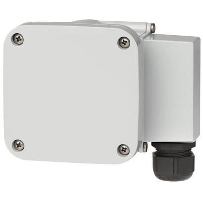
مفتاح كثافة الغاز
الوصف
مفتاح كثافة الغاز GDS-RC-HV مزوّد بحجرة مرجعية لمراقبة كثافة غاز SF6 في المعدات عالية الجهد. يعمل على مبدأ المقارنة مع حجم غاز مرجعي ملحوم، مما يوفر تعويضاً دقيقاً لدرجة الحرارة على خطوط التبديل المتساوية الحجم (isochore) في كامل نطاق درجات الحرارة. يُختار هذا الجهاز لمراقبة خزانات الغاز المغلقة وإطلاق إنذارات عند بلوغ قيم الحدود المحددة، مع تشخيص ذاتي يزيد من سلامة المحطة.
المزايا
- إيزوكور دقيق، تبديل معوّض حرارياً على كامل نطاق درجة الحرارة
- زيادة سلامة المنشأة عبر التشخيص الذاتي
- مهيأ لأي غازات بديلة
- استقرار طويل الأمد مرتفع جداً من خلال حجم الغاز المرجعي الملحوم
الأسئلة والأجوبة
ما هو نطاق ضغط هذا المفتاح؟
يتوفر بنطاقين: 0 … 10 bar و 0 … 12,5 bar.
هل يعوّض الجهاز تغيرات درجة الحرارة؟
نعم، يوفر تبديلاً متساوياً الحجم (isochore) دقيقاً ومُعوَّضاً حرارياً في كامل نطاق درجات الحرارة، وتُقاس الكثافة بالمرجعية إلى 20 °C.
ما هي وصلة العملية المتاحة؟
وصلة G 1/2 B وفق EN 837، محورية أو شعاعية.
ما هي درجة الحرارة المحيطة المسموح بها؟
من -40 °C إلى +80 °C.
ما هي درجة الحماية من ingress؟
IP65/IP67.
ما هي الشهادات المتوفرة؟
الشهادات CE و RoHS؛ لا توجد شهادات حماية من الانفجار في البيانات المتاحة.
ما الذي يميز طراز GDS-RC-HV عن غيره؟
وجود حجرة مرجعية بحجم غاز ملحوم يمنح ثباتاً طويل الأمد عالياً جداً، بالإضافة إلى التشخيص الذاتي والجاهزية لأي غازات بديلة.
كم جهة اتصال للتبديل يوفر الجهاز؟
يوفر 4 جهات اتصال للتبديل لإطلاق الإنذارات عند بلوغ قيم الحدود المحددة.
| الطراز | GDS-RC-HV |
| السلسلة | GDS |
| النوع الفرعي | Gas density switch with reference chamber |
| نطاق الضغط | 0…10 bar · 0…12.5 bar |
| درجة حرارة الكثافة المرجعية | 20 °C |
| وصلة العملية | G 1/2 B per EN 837, axial or radial |
| نقاط التبديل | 4 |
| مادة الأجزاء الملامسة | Stainless steel |
| حرارة المحيط | −40…+80 °C |
| تصنيف IP | IP65/IP67 |
| الوزن | 1.25 kg |
| الشهادات | CERoHS |
| تعويض درجة الحرارة | نعم |
| لغات ورقة البيانات | EN |
| Measurement principle | Reference gas measurement |
|---|---|
| Measuring range | ■ 0 ... 10 bar abs. at 20 °C [68 °F] SF₆ gas ■ 0 ... 12.5 bar abs. at 20 °C [68 °F] SF₆ gas |
| Self-indication in case of malfunc- tion | Integrated into the instrument, the switch contact is actuated in case of leakage in the reference chamber |
| Product label | Lasered onto the reference chamber, maximum weather resistance |
| Switching accuracy | |
|---|---|
| -1 ...+5 bar at 20 °C [68 °F] | ■ ±70 mbar at calibration pressure at 20 °C [68 °F], gaseous phase ■ ±100 mbar at calibration pressure at -30 …+50 °C [-22 ...+122 °F], gaseous phase |
| -1 ...+9 bar at 20 °C [68 °F] | ■ ±100 mbar at calibration pressure at 20 °C [68 °F], gaseous phase ■ ±150 mbar at calibration pressure at -30 …+50 °C [-22 ...+122 °F], gaseous phase |
| -1 ... +11.5 bar at 20 °C [68 °F] | ■ ±150 mbar at calibration pressure at 20 °C [68 °F], gaseous phase ■ ±200 mbar at calibration pressure at -30 …+50 °C [-22 ...+122 °F], gaseous phase |
| Switch model | Potential-free change-over contacts | ||
|---|---|---|---|
| Electrical connection | |||
| Electrical connection | 12-pin TTI plug-in terminal | ||
| Wire cross-section | ■ Min. 0.5 mm² ■ Max.2.5mm 2 | ||
| Grounding | Grounding in cable socket available | ||
| Quantity | ■ 1 micro switch ■ 2 micro switches ■ 3 micro switches ■ 4 micro switches Up to 4 micro switches possible as change-over contact | ||
| Switching directions | ■ Falling density ■ Rising density | ||
| Switch points | To customer specification, maximum difference of lowest to highest contact: 4 bar | ||
| Electrical characteristics | Switching voltage | Resistive load A | Inductive load A |
| ≤ DC 30V | 5 1) | 3 1) | |
| ≤ DC 50V | 1 | 1 | |
| ≤ DC 75V | 0,75 | 0.75 | |
| ≤ DC 125V | 0,5 | 0.03 | |
| ≤ DC 250V | 0,25 | 0.03 | |
| ≤ AC 125V | 5 1) | 2 1) | |
| ≤ AC 250V | 5 1) | 2 1) | |
| Minimum switching voltage and current | 12 V, 10mA | ||
| Calibration pressure | First switch point below filling pressure | ||
| Switching function | Change-over contact | ||
| Circuits | Galvanically isolated | ||
| Maximum number of cycles | 10,000 mechanical and electrical | ||
| Insulation resistance contact | > 100MOhm |
| Switch hysteresis | Measuring range | Hysteresis level |
|---|---|---|
| -1 ...+5 bar at 20 °C [68 °F] | Typical < 90 mbar 2) | |
| -1 ... +7.5 bar at 20 °C [68 °F] | Typical < 150 mbar 2) | |
| -1 ... +11.5 bar at 20 °C [68 °F] | Typical < 220 mbar 2) | |
| Lower switch hysteresis on request |
عرض الكل (10)
| Permissible ambient temperature | |
|---|---|
| Operating temperature | -40 ...+80 °C [-40 ...+176 °F], gaseous phase |
| Storage temperature | -50 ...+80 °C [-58 ... 176 °F] |
| Maximum load | |
| Minimum bursting strength | > 36 bar |
| Maximum overpressure | 1.43 times the measuring range |
| Ingress protection | IP65, IP67 |
| Permissible air humidity | ≤ 95 %r.h. (non-condensing) Compensating diaphragm against condensation |
| Shock resistance | ■ 50 g/11 ms: no contact bouncing at a distance of 200 mbar from the switch point ■ 150 g: no damage in all axes and directions |
| Vibration resistance | 4 g at a distance of 50 mbar from the switch point, no contact bouncing (20 ...80 Hz) |
| Dielectric strength | ■ 2 kV pin on grounding (case) ■ 2 kV pin on pin (micro switch on micro switch) ■ 1 kV pin on pin within micro switches - 1 minute |
|---|---|
| Lightning | 7 kV x 1.2/50 μs |
| Process connection | ≤ 1 x 10 -8 mbar x l/s |
|---|---|
| Bellows sealing | ≤ 1 x 10 -8 mbar x l/s |
| Wetted materials | |
|---|---|
| Reference chamber (pressure element) | Stainless steel, filling with reference gas |
| Process connection | G½BperEN837, axial or radial, stainless steel, spanner flats22mm |
| Other connections and connection locations on request | |
| Non-wetted materials | |
| Case and cover | Aluminium die-casting, powder-coated |
| Cable gland M25 x 1.5 | Plastic, sealing range 5 ... 13 mm;(optional 8 ... 17 mm) Tightening torque:8Nm |
| Logo | Description | Country |
|---|---|---|
| EU declaration of conformity ■ Low voltage directive ■ RoHS directive | European Union |
| Logo | Description |
|---|---|
| - | China RoHS directive |
لم تجد الإجابة في الوثائق؟ سيرد المهندس خلال يوم عمل.
اسأل المهندس →