
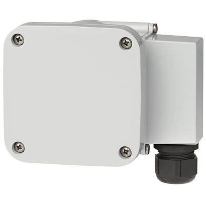
מתג צפיפות גז
תיאור
מתג צפיפות גז GDS-RC-HV של WIKA מנטר את צפיפות הגז SF6 בציוד מתח גבוה באמצעות תא ייחוס מרותך, עם פיצוי טמפרטורה לאורך כל טווח העבודה. המתג מפעיל התראה כאשר מושגים ערכי סף מוגדרים. הוא נבחר כאשר נדרשת בטיחות תפעולית גבוהה של מתקני מתח גבוה, כולל אבחון עצמי של המכשיר.
תכונות מיוחדות
- איזוכור מדויק, החלפה עם פיצוי טמפרטורה בכל טווח הטמפרטורות
- בטיחות מוגברת של המתקן באמצעות אבחון עצמי
- מוכן לכל גז חלופי
- יציבות ארוכת טווח גבוהה מאוד באמצעות נפח גז ייחוס מרותך
שאלות ותשובות
מה טווח הלחץ של ה-GDS-RC-HV?
המתג זמין בטווחי לחץ של 0 … 10 bar ו-0 … 12.5 bar.
מהו טווח הטמפרטורה הסביבתי המותר?
המכשיר פועל בטמפרטורות סביבה של -40 … +80 °C.
מהי דרגת ההגנה מפני חדירה?
דרגת ההגנה היא IP65/IP67.
איזה חיבור תהליך יש למתג?
החיבור הוא G 1/2 B per EN 837, בתצורה צירית (axial) או רדיאלית (radial).
מאיזה חומר עשויים החלקים במגע עם התווך?
החלקים במגע עם התווך עשויים Stainless steel (פלדת אל-חלד).
כמה מגעי מיתוג יש למכשיר?
ל-GDS-RC-HV יש 4 מגעי מיתוג.
אילו אישורים יש למכשיר?
המכשיר מאושר CE ו-RoHS. אין אישור אזורים מסוכנים בנתונים הזמינים.
מה מייחד את ה-GDS-RC-HV בהשוואה למתגי צפיפות אחרים?
הוא כולל תא ייחוס מרותך ליציבות ארוכת טווח גבוהה, פיצוי טמפרטורה מדויק לאורך איזוכורה, אבחון עצמי להגברת בטיחות המתקן, והוא מוכן לכל גז חלופי.
| דגם | GDS-RC-HV |
| סדרה | GDS |
| תת-קטגוריה | Gas density switch with reference chamber |
| טווח לחץ | 0…10 bar · 0…12.5 bar |
| טמפרטורת ייחוס לצפיפות | 20 °C |
| חיבור תהליך | G 1/2 B per EN 837, axial or radial |
| מגעי מתג | 4 |
| חומר חלקים רטובים | Stainless steel |
| טמפ׳ סביבה | −40…+80 °C |
| דרגת הגנה IP | IP65/IP67 |
| משקל | 1.25 kg |
| תקנים | CERoHS |
| פיצוי טמפרטורה | כן |
| שפות גיליון נתונים | EN |
| Measurement principle | Reference gas measurement |
|---|---|
| Measuring range | ■ 0 ... 10 bar abs. at 20 °C [68 °F] SF₆ gas ■ 0 ... 12.5 bar abs. at 20 °C [68 °F] SF₆ gas |
| Self-indication in case of malfunc- tion | Integrated into the instrument, the switch contact is actuated in case of leakage in the reference chamber |
| Product label | Lasered onto the reference chamber, maximum weather resistance |
| Switching accuracy | |
|---|---|
| -1 ...+5 bar at 20 °C [68 °F] | ■ ±70 mbar at calibration pressure at 20 °C [68 °F], gaseous phase ■ ±100 mbar at calibration pressure at -30 …+50 °C [-22 ...+122 °F], gaseous phase |
| -1 ...+9 bar at 20 °C [68 °F] | ■ ±100 mbar at calibration pressure at 20 °C [68 °F], gaseous phase ■ ±150 mbar at calibration pressure at -30 …+50 °C [-22 ...+122 °F], gaseous phase |
| -1 ... +11.5 bar at 20 °C [68 °F] | ■ ±150 mbar at calibration pressure at 20 °C [68 °F], gaseous phase ■ ±200 mbar at calibration pressure at -30 …+50 °C [-22 ...+122 °F], gaseous phase |
| Switch model | Potential-free change-over contacts | ||
|---|---|---|---|
| Electrical connection | |||
| Electrical connection | 12-pin TTI plug-in terminal | ||
| Wire cross-section | ■ Min. 0.5 mm² ■ Max.2.5mm 2 | ||
| Grounding | Grounding in cable socket available | ||
| Quantity | ■ 1 micro switch ■ 2 micro switches ■ 3 micro switches ■ 4 micro switches Up to 4 micro switches possible as change-over contact | ||
| Switching directions | ■ Falling density ■ Rising density | ||
| Switch points | To customer specification, maximum difference of lowest to highest contact: 4 bar | ||
| Electrical characteristics | Switching voltage | Resistive load A | Inductive load A |
| ≤ DC 30V | 5 1) | 3 1) | |
| ≤ DC 50V | 1 | 1 | |
| ≤ DC 75V | 0,75 | 0.75 | |
| ≤ DC 125V | 0,5 | 0.03 | |
| ≤ DC 250V | 0,25 | 0.03 | |
| ≤ AC 125V | 5 1) | 2 1) | |
| ≤ AC 250V | 5 1) | 2 1) | |
| Minimum switching voltage and current | 12 V, 10mA | ||
| Calibration pressure | First switch point below filling pressure | ||
| Switching function | Change-over contact | ||
| Circuits | Galvanically isolated | ||
| Maximum number of cycles | 10,000 mechanical and electrical | ||
| Insulation resistance contact | > 100MOhm |
| Switch hysteresis | Measuring range | Hysteresis level |
|---|---|---|
| -1 ...+5 bar at 20 °C [68 °F] | Typical < 90 mbar 2) | |
| -1 ... +7.5 bar at 20 °C [68 °F] | Typical < 150 mbar 2) | |
| -1 ... +11.5 bar at 20 °C [68 °F] | Typical < 220 mbar 2) | |
| Lower switch hysteresis on request |
הצגת הכול (10)
| Permissible ambient temperature | |
|---|---|
| Operating temperature | -40 ...+80 °C [-40 ...+176 °F], gaseous phase |
| Storage temperature | -50 ...+80 °C [-58 ... 176 °F] |
| Maximum load | |
| Minimum bursting strength | > 36 bar |
| Maximum overpressure | 1.43 times the measuring range |
| Ingress protection | IP65, IP67 |
| Permissible air humidity | ≤ 95 %r.h. (non-condensing) Compensating diaphragm against condensation |
| Shock resistance | ■ 50 g/11 ms: no contact bouncing at a distance of 200 mbar from the switch point ■ 150 g: no damage in all axes and directions |
| Vibration resistance | 4 g at a distance of 50 mbar from the switch point, no contact bouncing (20 ...80 Hz) |
| Dielectric strength | ■ 2 kV pin on grounding (case) ■ 2 kV pin on pin (micro switch on micro switch) ■ 1 kV pin on pin within micro switches - 1 minute |
|---|---|
| Lightning | 7 kV x 1.2/50 μs |
| Process connection | ≤ 1 x 10 -8 mbar x l/s |
|---|---|
| Bellows sealing | ≤ 1 x 10 -8 mbar x l/s |
| Wetted materials | |
|---|---|
| Reference chamber (pressure element) | Stainless steel, filling with reference gas |
| Process connection | G½BperEN837, axial or radial, stainless steel, spanner flats22mm |
| Other connections and connection locations on request | |
| Non-wetted materials | |
| Case and cover | Aluminium die-casting, powder-coated |
| Cable gland M25 x 1.5 | Plastic, sealing range 5 ... 13 mm;(optional 8 ... 17 mm) Tightening torque:8Nm |
| Logo | Description | Country |
|---|---|---|
| EU declaration of conformity ■ Low voltage directive ■ RoHS directive | European Union |
| Logo | Description |
|---|---|
| - | China RoHS directive |
לא מצאתם תשובה בתיעוד? מהנדס יענה במהלך יום עסקים.
שאלו מהנדס →