
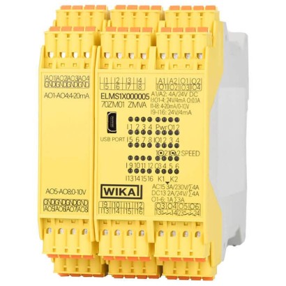
Safety electronics
Description
The model ELMS1 safety electronics is a multi-functional and confi gurable safety switching device. The electronics consist of a control module and individual function modules that can be mounted next to each other. The modules are connected to each other via a redundant, standard DIN-rail bus. The safety electronics feature a wide range of safety digital and analogue inputs, safety solid-state and safe contact outputs. Several analogue outputs and also fi eldbus modules are available for those non-safety-relevant parts of the application during normal operation. The status of the inputs and outputs, operating voltage and other diagnostic messages are displayed on a LED matrix.
The control module of the safety electronics is certifi ed in accordance with DIN EN 13849-1 Category 4 PLe through DGUV. Based on Table 3 of DIN EN 13849-1, this corresponds to SIL 3.
Safety electronics, model ELMS1
Special features
- Certified safety electronics, certified in accordance with DIN EN ISO 13849-1, PLe
- Certified system solution incl. force measurement, certified in accordance with DIN EN 13849-1 Cat. 3, PLd
- 16 x safe inputs (8 x 4 ... 20 mA analogue inputs, 8 x digital inputs), 2 x safe relay outputs and 6 x safe solid-state outputs (positive switching)
- Additional module with ProfiBus ® , ProfiNet ® , EtherCat ® and CANopen ®
- Complex functionality, easy to configure via PC
| Model | ELMS1 |
| Product family | ELMS |
| Subcategory | Safety electronics |
| Force ranges | 0…3 kN · 0…100 kN · 0…2 kN · 0…10 kN · 0…10000 kN |
| Accuracy class | ±3 % of full scale |
| Safety integrity level (SIL) | SIL 3 |
| Mounting type | DIN rail |
| Output signal | 4 ... 20 mA / DC 0 … 10 V |
| Cell material | Polyamide (PA), non-reinforced, stainless steel |
| Ambient temperature | −10…+55 °C |
| IP rating | IP20 |
| Weight | 0.45 kg |
| Certifications | RoHS |
| Datasheet languages | EN |
| Model ELMS1 | |
|---|---|
| Analog input | |
| Input signal | 4 ...20mA/DC0…10V |
| Current inputs | 4…20mA |
| Input resistance | 4 …20mA:approx.500 Ω, DC 0 …10V:> 5 kΩ |
| Accuracy | ±3 %of full scale |
| Digital input | |
| Voltage at the inputs | DC 24V -15 %, +10 %, ≤ 10 %residual ripple |
| Current supply | max.4mA |
| Input frequency | at I9 to I12 ≤ 500 Hz via 2 sensors e.g. proximity sensors at I9 to I16 ≤ 50 kHz with HTL signals via incremental measuring system |
| Rated temperature range | -10 …+55 °C |
| Storage temperature range | -40 …+85 °C |
| Relay output | |
| Minimum switching current | 10mA |
| Switching capacity per DIN EN 60947-4-1/ EN 60947-5-1 | DC1:24V / 6 A DC13:24V / 5 A |
| Total of switching and continuous currents | K3, K4: ≤ 6 A K5, K6: ≤ 6 A |
| Service life at switching capacity:DC13 | DC 24 V/ 1 A: 1 x 10 5 DC 24 V/ 4 A: 4 x 10 4 |
| Maximum number of cycles | DC13 4 A: 360 cycles/h |
| Mechanical lifetime | > 10 7 h |
| Solid-state output | |
| Minimum switching current | 1mA |
| Switching current and continuous current | IO1-IO4: 0.25 A O1-O6: 1 A |
| Total of switching and continuous current | IO1-IO4: 0.8 A O1-O6: 3 A |
| Other outputs | Profibus DP, ProfiNet , EtherCat, CANopen ® etc. |
| Supply voltage | DC 24V -15 %, + 10 %/ max. residual ripple10% |
| Power consumption | 3.0W |
| Response time | |
| Operate and disengaging time | 100 ms |
| Total response time of the safety function | typically (relay): 10 ms / 3 ms |
| Terminals | Spring-loaded terminals, plug-in |
| Connection cross-section | 0.2 ..1.5mm 2 (AWG24-16) with end splices |
| Lead | only 60/75 °C copper |
| Connection diagram | a wiring diagram will be created and delivered with every project |
| Case material | Polyamide (PA), non-reinforced |
| Ingress protection | Cases and terminals: IP20 / minimum requirement for the installation location IP54 |
| Electromagnetic compatibility | DIN EN 61326-1: 2013-07 DIN EN 61326-3-1: 2015-06 EN 55011: 2009+A1: 2010 (class A) |
| RoHS | EN 50581:2012 |
| Safety | Category 4, PLe based on Table 3 of DIN EN 13849-1: 2016-06, this corresponds |
| Mounting | to SIL 3 on DIN rail, 35 mm, per EN 60715:2001 |
| Weight | approx. 450 g |
| Model ELMS1 | With display | In the control cabinet |
|---|---|---|
| Version | Only in combination with a CANopen ® module, 4.3'TFT touchscreen with LED backlighting Dimensions (W x H x D) 140 x 100x5mm | installed |
| Rated temperature range | 0…50°C | -10 …+50 °C |
| Storage temperature range | -25 …+75 °C | -40 …+85 °C |
| Supply voltage | AC 230V | |
| Ingress protection | IP65 |
| Module ELMS1 | Dimensions inmm | ||
|---|---|---|---|
| Height (H) | Width (W) | Depth (D) | |
| Control module | 114 | 67.5 | 99 |
| Extensions | 114 | 22.5 | 99 |
| Model | Description | |
|---|---|---|
| F23S1 | Tension/compression force transducers ■ Measuring ranges 0 ... 3 to 0 ... 100 kN ■ Material: stainless steel (corrosion-resistant) ■ Integrated amplifier ■ For further technical information, see data sheet FO 51.17 | |
| F33S1 | Shear beam ■ Measuring ranges 0 ... 2 kN to 0 ... 100 kN ■ Material: stainless steel (corrosion-resistant) ■ Integrated amplifier ■ For further technical information, see data sheet FO 51.42 | |
| F53S8 | Heavy-duty load pin ■ Measuring ranges as of 0 ... 10 kN ■ Material: stainless steel (corrosion-resistant) ■ Integrated amplifier ■ For further technical information, see data sheet FO 51.43 | |
| F73S1 | Tension link ■ 0 ... 5 to 0 ... 10,000 kN ■ Material: stainless steel (corrosion-resistant) ■ Integrated amplifier ■ For further technical information, see data sheet FO 51.19 | |
| EZE53 | Cable ■ Resistant to seawater ■ UV-resistant |
Couldn't find the answer in the documentation? An engineer will reply within a business day.
Ask an engineer →