
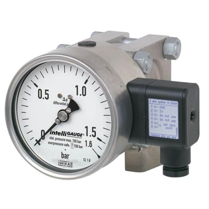
Differential pressure gauge with output signal
Description
Wherever the differential pressure must be indicated on site and, at the same time, a signal transmission to the central control or control room is desired, the model DPGT43HP intelliGAUGE ® (patent, property right: e.g. DE 202007019025) can be used.
The model DPGT43HP is based upon a model 732.14 high-quality, stainless steel pressure gauge with a nominal size of 100 or 160. The pressure measuring instrument is manufactured in accordance with EN 837-3.
The use of high-quality stainless steel materials and the robust design are geared to applications in the chemical and process engineering industries. Thus the instrument is suitable for liquid and gaseous media, also in aggressive environments.
A high overload safety is achieved by the all-metal construction and the close-fitting design of the measuring element.
Special features
- High operating pressure (static pressure) and high overload safety, selectable up to 40, 100, 250, 400 or 650 bar
- Measuring cell liquid damping against rapid pressure changes
- No configuration necessary due to “plug-and-play”
- QR code on dial links to instrument-specific information
- Individual, non-linear characteristic curves (e.g. x 2 or √x for flow measurement)
| Model | DPGT43HP.100 |
| Product family | DPGT43HP |
| Subcategory | Differential pressure gauge with output signal |
| Pressure ranges | 0…60 mbar · 0…160 mbar · 0…0.25 bar · 0…40 bar · 0…0.4 bar · 0…250 mbar |
| Accuracy class | 1.6 |
| Accuracy standard | EN 837-3 |
| Process connection | G ½ femaleG ½ B male½ NPT maleDifferential process connection per EN 61518 |
| Process temperature | −20…+100 °C |
| Output signal | 4 ... 20 mA · 0 ... 20 mA · 0 ... 10 V |
| Power supply | DC 12 V < U ≤ 30 V |
| Electrical connection | Cable socket PA 6, black, cable gland M20 x 1.5, 6 screw terminals + PE |
| Case material | Stainless steel |
| Wetted parts material | Stainless steel 316L, NiCr alloy (Inconel) |
| Sealing material | FPM/FKM |
| Ambient temperature | −20…+70 °C |
| IP rating | IP54 |
| Weight | 3.6 kg |
| Certifications | CERoHSNACE MR0175/ISO 15156NACE MR0103/ISO 17945EACREACH |
| Explosion protection | [II 2G Ex ia IIC T6/T5/T4 Gb][II 2D Ex ia IIIB T85°C/T100°C/T135°C Db][Ex ia IIC T6/T5/T4 Gb][Ex ia IIIB T85°C/T100°C/T135°C Db]ATEXIECExII 2G Ex ia IIC T6/T5/T4 GbII 2D Ex ia IIIB T85℃/T100℃/T135℃ DbEx ia IIC T6/T5/T4 GbEx ia IIIB T85℃/T100℃/T135℃ Db |
| Dial size | 100 mm |
| Datasheet languages | EN, DE, ES, FR, IT, PT, NL, PL, RU, ZH, JA, KO, TR, AR, CS, HU, RO, SK, TH, UK, VI |
| Version | Highest overload safety either side, pressure ratings PN 40, 100, 250, 400 or 650. Pressure transmis - sion medium of the measuring cell causes damping of the indication. Full-scale loadable per EN 837-3. |
|---|---|
| Nominal size inmm | ■ 100 ■ 160 |
| Accuracy class | 1.6 Option: ■ 1.0 (application test required) ■ 2.5 (Monel or Hastelloy version) |
| Scale ranges | Instruments with PN 40 and 100: ■ 0 …60mbar to 0 …160 mbar (measuring cell □140) ■ 0 …0.25 bar to 0 …40bar (measuring cell □82) Instruments with PN 250: ■ 0 …60mbar to 0 …250 mbar (measuring cell □140) ■ 0 …0.4 bar to 0 …40bar (measuring cell □82) Instruments with PN 400 and 650: 0 …0.4 bar to 0 …40bar (measuring cell □86) Dimensions of measuring cells from page 6 Other units (e.g. psi, kPa) available as well as all other vacuum and compound measuring ranges |
| Scale | Single scale Option: ■ Dual scale ■ Scale layout with individual non-linear characteristic curves |
| Zero point setting | By means of adjustment appliance |
| Pressure limitation | |
| Steady | Full scale value |
| Fluctuating | 0.9 x full scale value Observe the recommendations for the use of mechanical pressure measuring systems in accordance with EN 837-2 |
| Overload safety and max. operating pressure (static pressure) | Instruments with PN 40, 100, 250 and 400: ■ Max. 40, 100, 250 or 400 bar [580, 1,450, 3,625 or 5,800 psi], on one, both and alternatingly on the ⊕and ⊖sides Instruments with PN 650: ■ Max. 400 bar [5,800 psi], on one side and alternatingly on the ⊕and ⊖sides ■ Max. 650 bar [9,425 psi], on both the ⊕and ⊖sides |
| Connection location | Lower mount (radial) Option: ■ Back mount ■ Connection at 12 o'clock |
| Process connection | ■ G½female ■ G½Bmale ■ ½NPTmale ■ Differential process connection per EN 61518 Other process connections via female or male threads on request |
| Permissible temperature 1) | |
| Medium | -20 ...+100 °C |
| Ambient | -20 ...+60 °C Option: -40 ...+60 °C (silicone oil filling) |
| Temperature effect | When the temperature of the measuring system deviates from the reference temperature (+20 °C): max. ±0.5 %/10 K of full scale value |
| Case filling | Without Option: With case filling |
| Venting of the media chambers | ■ Instruments with PN 40 and 100: for scale ranges ≤ 0.16 bar 1) (option for scale ranges ≥ 0.25 bar) 1) ■ Instruments with PN 250, 400 and 650: standard for scale ranges ≤ 0.25 bar 2) (option for scales ranges ≥ 0.4 bar) 2) |
|---|---|
| Pressure transmission medium of the measuring cell | Silicone oil Option: Measuring cell filling with special medium, e.g. for use in oxygen applications Others on request |
| Materials (wetted) | |
| Measuring flanges with process connection | Stainless steel 316L |
| Pressure elements 2) | ■ ≤ 0.25 bar: stainless steel 316L ■ ≥ 0.4 bar: NiCr alloy (Inconel) |
| Venting of the media chambers | Stainless steel 316L |
| Seals | FPM/FKM |
| Materials (non-wetted) | |
| Intermediate flange | ■ PN 40 / 100: stainless steel ■ PN 250 / 400 / 650: chromium steel |
| Flange connecting screws | ■ PN 40 / 100: stainless steel ■ PN 250 / 400 / 650: steel, corrosion-protected |
| Case, movement, bayonet bezel | Stainless steel |
| Dial | Aluminium, white, black lettering |
| Pointer | Aluminium, black |
| Window | ■ Laminated safety glass ■ Polycarbonate |
| Ingress protection per IEC/EN 60529 | IP54 Option: IP65 with liquid filling |
| Installation | According to affixed symbols:⊕high pressure, ⊖low pressure |
| Mounting | ■ Rigid measuring lines ■ Drilled mounting holes at the back of the measuring cell Option: ■ Panel mounting flange ■ Instrument mounting bracket for wall or pipe mounting |
| Output signal | Variant 1: 4 …20mA, 2-wire, passive, per NAMUR NE 43 Variant 2: 4 ... 20 mA, 2-wire, for hazardous areas Variant 3: 0 ... 20 mA, 3-wire Variant 4: 0 ... 10 V, 3-wire |
|---|---|
| Auxiliary power U B | DC 12V < U B ≤ 30V (variant 1 and 3) DC 14V < U B ≤ 30V (variant 2) DC 15V < U B ≤ 30V (variant 4) |
| Influence of auxiliary power | ≤ 0.1 %of full scale/10V |
| Permissible residual ripple of U B | ≤ 10 %ss |
| Permissible max. load R A | Variant 1, 2, 3:R A ≤ (U B - 12 V)/0.02 A with R A in Ωand U B in V, however max.600Ω Variant 4:R A = 100 kΩ |
| Influence of load (variant 1, 2, 3) | ≤ 0.1 %of full scale |
| Impedance at voltage output | 0.5Ω |
| Electrical zero point | Through a jumper across terminals 5 and 6 (see operating instructions) |
| Long-term stability of electronics | < 0.3 %of full scale per year |
| Electr. output signal | ≤ 1 %of measuring span |
| Linear error | ≤ 1 %of measuring span (terminal method) |
| Resolution | 0.13 %of full scale (10 bit resolution at 360°) |
| Refresh rate (measuring interval) | 600 ms |
| Electrical connection | Cable socket PA 6, black PerVDE 0110 insulation group C/250V Cable gland M20 x 1.5 Strain relief 6 screw terminals + PE for conductor cross-section 2.5 mm² |
| Assignment of connection termi - nals, 2-wire (variant 1 and 2) | Do not use this terminal U B +/I+ Terminals 3 and 4: for internal use only Terminals 5 and 6: reset zero point |
| For assignment of connection terminals for 3-wire (variant 3 and 4), see operating instructions | +0V/GND |
| Ui | Ii | Pi | Ci | Li |
|---|---|---|---|---|
| DC 30V | 100mA | 720mW | 11 nF | Negligible |
View all (15)
| T6 | T5 | T4 ...T1 |
|---|---|---|
| -20 ...+45 °C | -20 ...+60 °C | -20 ...+70 °C |
| T85°C | T100°C | T135°C |
|---|---|---|
| -20 ...+45 °C | -20 ...+60 °C | -20 ...+70 °C |
| Logo | Description | Region |
|---|---|---|
| EU declaration of conformity | European Union | |
| EMCDirective | ||
| Pressure Equipment Directive PS > 200 bar, module A, pressure accessory | ||
| RoHS directive |
| Logo | Description | Region |
|---|---|---|
| EU declaration of conformity | European Union | |
| IECEx Hazardous areas - Ex ia Gas [Ex ia IIC T6/T5/T4 Gb] Dust [Ex ia IIIB T85°C/T100°C/T135°C Db] | International | |
| EAC EMCDirective | Eurasian Economic Community | |
| Ex Ukraine Hazardous areas | Ukraine | |
| NEPSI Hazardous areas | China | |
| PAC Kazakhstan Metrology, measurement technology | Kazakhstan | |
| PAC Ukraine Metrology, measurement technology | Ukraine | |
| PAC Uzbekistan Metrology, measurement technology | Uzbekistan | |
| - | PAC China Metrology, measurement technology | China |
| - | CRN Safety (e.g. electr. safety, overpressure, ...) | Canada |
| Certificates | ■ 2.2 test report per EN 10204 (e.g. state-of-the-art manufacturing, indication accuracy) ■ 3.1 inspection certificate per EN 10204 (e.g. material proof for wetted metal parts, indication accuracy) |
|---|---|
| Recommended calibration interval | 1 year (dependent on conditions of use) |
| Patent number | Description |
|---|---|
| DE 202007019025, US 2010045366, CN 101438333 | Pointer measuring instrument with output signal 4 ...20mA |
| US Design D1051747S, CPC CN 01677074, DE Design 402022100171, EU Design 402022100171, IR Design DM/222416, EU 3D trademark 018659564 | WIKA blue identity design patent |
| NS | Scale range 1) | Dimensions inmm | Weight in kg 2) | ||||||
|---|---|---|---|---|---|---|---|---|---|
| b | D1 | h ±1 | p□ PN 40 ... 250 | p□ PN 400, 650 | PN 40, 100 | PN 250 | PN 400, 650 | ||
| 100 | ≤ 0.25 bar [3.63 psi] | 58.5 | 101 | 86 | 140 | - | 12.1 | 13.1 | - |
| ≥ 0.4 bar [5.8 psi] | 58.5 | 101 | 64 | 82 | 86 | 3.6 | 3.9 | 4.5 | |
| 160 | ≤ 0.25 bar [3.63 psi] | 65.5 | 161 | 86 | 140 | - | 12.5 | 13.5 | - |
| ≥ 0.4 bar [5.8 psi] | 65.5 | 161 | 64 | 82 | 86 | 4.0 | 4.3 | 4.9 |
| Model | Description | Order number |
|---|---|---|
| 910.33 | Adhesive label set for red and green circular arcs →See data sheet AC 08.03 | - |
| NS 100 [4"] | 14238945 | |
| NS 160 [6"] | 14228352 | |
| 910.17 | Seals →See data sheet AC 09.08 | On request |
| 910.13 | Overpressure protector →See data sheet AC 09.04 | On request |
| IV315 | 3-valve manifold Process connection / Instrument connection: 2 x G½, male thread / 2 x G½, male nut | 81640945 |
| 3-valve manifold Process connection / Instrument connection: 2 x ½NPT, male thread / 2 x G½, male nut | 36709683 | |
| IV515 2 x | 5-valve manifold Process connection / instrument connection / Vent connection: G½, male thread / 2 x G½, male nut / 2 x G¼, female thread | 83141757 |
| 5-valve manifold Process connection / instrument connection / Vent connection: 2 x ½NPT, male thread / 2 x G½, male nut / 2 x G¼, female thread | 84050640 | |
| Other valve manifolds for differential pressure measuring instruments →See data sheet AC 09.23 | On request | |
| - | Instrument mounting bracket for wall or pipe mounting Steel, silver painted | 2393340 |
| Instrument mounting bracket for wall or pipe mounting Stainless steel | 2094941 |
| NS | Scale range 1) | Dimensions in mm[in] | |
|---|---|---|---|
| C1 | C2 | ||
| 100 [4"] | ≤ 0.16 bar [2.3 psi] | 97 [3.82] | 115 [4.53] |
| ≥ 0.25 bar [3.6 psi] | 68 [2.68] | 86 [3.39] | |
| 160 [6"] | ≤ 0.16 bar [2.3 psi] | 97 [3.82] | 115 [4.53] |
| ≥ 0.25 bar [3.6 psi] | 68 [2.68] | 86 [3.39] |
| NS | Scale range 1) | Dimensions in mm[in] | |
|---|---|---|---|
| C1 | C2 | ||
| 100 [4"] | ≤ 0.25 bar [3.6 psi] | 97 [3.82] | 115 [4.53] |
| ≥ 0.4 bar [5.8 psi] | 68 [2.68] | 86 [3.39] | |
| 160 [6"] | ≤ 0.25 bar [3.6 psi] | 97 [3.82] | 115 [4.53] |
| ≥ 0.4 bar [5.8 psi] | 68 [2.68] | 86 [3.39] |
| NS | Dimensions in mm[in] | |
|---|---|---|
| C1 | C2 | |
| 100 [4"] | 70 [2.76] | 88 [3.46] |
| 160 [6"] | 70 [2.76] | 88 [3.46] |
Couldn't find the answer in the documentation? An engineer will reply within a business day.
Ask an engineer →