
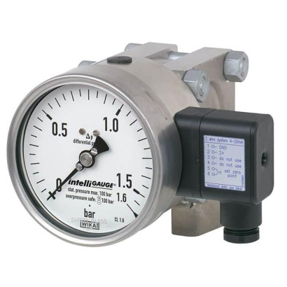
מד לחץ דיפרנציאלי עם אות יציאה
תיאור
בכל מקום שבו יש צורך להציג לחץ דיפרנציאלי באתר, ובו-בזמן נדרש שידור אות לחדר הבקרה המרכזי או למערכת הבקרה, ניתן להשתמש בדגם DPGT43HP intelliGAUGE ® (פטנט, זכות קניין: למשל DE 202007019025).
הדגם DPGT43HP מבוסס על מד לחץ איכותי מדגם 732.14 מפלדת אל-חלד, במידות נומינליות של 100 או 160. מכשיר מדידת הלחץ מיוצר בהתאם ל-EN 837-3.
השימוש בחומרי פלדת אל-חלד באיכות גבוהה ובמבנה קשיח מכוון ליישומים בתעשיות ההנדסה הכימית וההנדסה לתהליכים. לכן המכשיר מתאים למדיות נוזליות וגזיות, גם בסביבות אגרסיביות.
בטיחות גבוהה מפני עומס יתר מושגת באמצעות מבנה כולו-מתכתי ותכנון צמוד של אלמנט המדידה.
תכונות מיוחדות
- לחץ הפעלה (לחץ סטטי) ובטיחות יתר עומס גבוהים, לבחירה עד 40, 100, 250, 400 או 650 bar
- ריסון נוזלי של תא המדידה נגד שינויי לחץ מהירים
- אין צורך בהגדרה בזכות “plug-and-play”
- קוד QR על השעונית המקשר למידע ייחודי למכשיר
- עקומות אפיון בלתי-ליניאריות מותאמות אישית (למשל x 2 או √x למדידת זרימה)
שאלות ותשובות
מהו טווח המדידה של ה-DPGT43HP?
הטווחים הזמינים הם 0 … 60 mbar, 0 … 160 mbar, 0 … 250 mbar, 0 … 0.25 bar, 0 … 0.4 bar ו-0 … 40 bar.
מהי מחלקת הדיוק של המכשיר?
מחלקת דיוק 1.6 לפי EN 837-3.
אילו אותות מוצא המכשיר תומך?
4 ... 20 mA, 0 ... 20 mA ו-0 ... 10 V, עם אספקת חשמל DC 12 V < U ≤ 30 V.
אילו חיבורי תהליך זמינים?
G ½ female, G ½ B male, ½ NPT male, וכן חיבור תהליך דיפרנציאלי לפי EN 61518.
מהם חומרי החלקים במגע עם המדיום?
Stainless steel 316L או NiCr alloy (Inconel), עם אטימה מ-FPM/FKM — מתאים למדיות נוזליות וגזיות, גם בסביבות אגרסיביות.
מהם טווחי הטמפרטורה המותרים?
טמפרטורת סביבה -20 … +70 °C וטמפרטורת מדיום -20 … +100 °C.
האם המכשיר מאושר לאזורים עם סיכון פיצוץ?
כן — ATEX ו-IECEx: II 2G Ex ia IIC T6/T5/T4 Gb ו-II 2D Ex ia IIIB T85°C/T100°C/T135°C Db.
מה מייחד את ה-DPGT43HP ממדי לחץ דיפרנציאלי אחרים?
בטיחות גבוהה מפני עומס יתר עד 650 bar, לחץ עבודה סטטי גבוה, ריסון נוזלי של תא המדידה, פעולת "plug-and-play" ללא הגדרה, ועקומות אפיון לא-ליניאריות אישיות (למשל √x למדידת זרימה).
| דגם | DPGT43HP.100 |
| סדרה | DPGT43HP |
| תת-קטגוריה | Differential pressure gauge with output signal |
| טווח לחץ | 0…60 mbar · 0…160 mbar · 0…0.25 bar · 0…40 bar · 0…0.4 bar · 0…250 mbar |
| מחלקת דיוק | 1.6 |
| תקן דיוק | EN 837-3 |
| חיבור תהליך | G ½ femaleG ½ B male½ NPT maleDifferential process connection per EN 61518 |
| טמפ׳ תהליך | −20…+100 °C |
| אות יציאה | 4 ... 20 mA · 0 ... 20 mA · 0 ... 10 V |
| הזנה | DC 12 V < U ≤ 30 V |
| חיבור חשמלי | Cable socket PA 6, black, cable gland M20 x 1.5, 6 screw terminals + PE |
| חומר מארז | Stainless steel |
| חומר חלקים רטובים | Stainless steel 316L, NiCr alloy (Inconel) |
| חומר אטם | FPM/FKM |
| טמפ׳ סביבה | −20…+70 °C |
| דרגת הגנה IP | IP54 |
| משקל | 3.6 kg |
| תקנים | CERoHSNACE MR0175/ISO 15156NACE MR0103/ISO 17945EACREACH |
| הגנת התפוצצות | [II 2G Ex ia IIC T6/T5/T4 Gb][II 2D Ex ia IIIB T85°C/T100°C/T135°C Db][Ex ia IIC T6/T5/T4 Gb][Ex ia IIIB T85°C/T100°C/T135°C Db]ATEXIECExII 2G Ex ia IIC T6/T5/T4 GbII 2D Ex ia IIIB T85℃/T100℃/T135℃ DbEx ia IIC T6/T5/T4 GbEx ia IIIB T85℃/T100℃/T135℃ Db |
| קוטר חוגה | 100 mm |
| שפות גיליון נתונים | EN, DE, ES, FR, IT, PT, NL, PL, RU, ZH, JA, KO, TR, AR, CS, HU, RO, SK, TH, UK, VI |
| Version | Highest overload safety either side, pressure ratings PN 40, 100, 250, 400 or 650. Pressure transmis - sion medium of the measuring cell causes damping of the indication. Full-scale loadable per EN 837-3. |
|---|---|
| Nominal size inmm | ■ 100 ■ 160 |
| Accuracy class | 1.6 Option: ■ 1.0 (application test required) ■ 2.5 (Monel or Hastelloy version) |
| Scale ranges | Instruments with PN 40 and 100: ■ 0 …60mbar to 0 …160 mbar (measuring cell □140) ■ 0 …0.25 bar to 0 …40bar (measuring cell □82) Instruments with PN 250: ■ 0 …60mbar to 0 …250 mbar (measuring cell □140) ■ 0 …0.4 bar to 0 …40bar (measuring cell □82) Instruments with PN 400 and 650: 0 …0.4 bar to 0 …40bar (measuring cell □86) Dimensions of measuring cells from page 6 Other units (e.g. psi, kPa) available as well as all other vacuum and compound measuring ranges |
| Scale | Single scale Option: ■ Dual scale ■ Scale layout with individual non-linear characteristic curves |
| Zero point setting | By means of adjustment appliance |
| Pressure limitation | |
| Steady | Full scale value |
| Fluctuating | 0.9 x full scale value Observe the recommendations for the use of mechanical pressure measuring systems in accordance with EN 837-2 |
| Overload safety and max. operating pressure (static pressure) | Instruments with PN 40, 100, 250 and 400: ■ Max. 40, 100, 250 or 400 bar [580, 1,450, 3,625 or 5,800 psi], on one, both and alternatingly on the ⊕and ⊖sides Instruments with PN 650: ■ Max. 400 bar [5,800 psi], on one side and alternatingly on the ⊕and ⊖sides ■ Max. 650 bar [9,425 psi], on both the ⊕and ⊖sides |
| Connection location | Lower mount (radial) Option: ■ Back mount ■ Connection at 12 o'clock |
| Process connection | ■ G½female ■ G½Bmale ■ ½NPTmale ■ Differential process connection per EN 61518 Other process connections via female or male threads on request |
| Permissible temperature 1) | |
| Medium | -20 ...+100 °C |
| Ambient | -20 ...+60 °C Option: -40 ...+60 °C (silicone oil filling) |
| Temperature effect | When the temperature of the measuring system deviates from the reference temperature (+20 °C): max. ±0.5 %/10 K of full scale value |
| Case filling | Without Option: With case filling |
| Venting of the media chambers | ■ Instruments with PN 40 and 100: for scale ranges ≤ 0.16 bar 1) (option for scale ranges ≥ 0.25 bar) 1) ■ Instruments with PN 250, 400 and 650: standard for scale ranges ≤ 0.25 bar 2) (option for scales ranges ≥ 0.4 bar) 2) |
|---|---|
| Pressure transmission medium of the measuring cell | Silicone oil Option: Measuring cell filling with special medium, e.g. for use in oxygen applications Others on request |
| Materials (wetted) | |
| Measuring flanges with process connection | Stainless steel 316L |
| Pressure elements 2) | ■ ≤ 0.25 bar: stainless steel 316L ■ ≥ 0.4 bar: NiCr alloy (Inconel) |
| Venting of the media chambers | Stainless steel 316L |
| Seals | FPM/FKM |
| Materials (non-wetted) | |
| Intermediate flange | ■ PN 40 / 100: stainless steel ■ PN 250 / 400 / 650: chromium steel |
| Flange connecting screws | ■ PN 40 / 100: stainless steel ■ PN 250 / 400 / 650: steel, corrosion-protected |
| Case, movement, bayonet bezel | Stainless steel |
| Dial | Aluminium, white, black lettering |
| Pointer | Aluminium, black |
| Window | ■ Laminated safety glass ■ Polycarbonate |
| Ingress protection per IEC/EN 60529 | IP54 Option: IP65 with liquid filling |
| Installation | According to affixed symbols:⊕high pressure, ⊖low pressure |
| Mounting | ■ Rigid measuring lines ■ Drilled mounting holes at the back of the measuring cell Option: ■ Panel mounting flange ■ Instrument mounting bracket for wall or pipe mounting |
| Output signal | Variant 1: 4 …20mA, 2-wire, passive, per NAMUR NE 43 Variant 2: 4 ... 20 mA, 2-wire, for hazardous areas Variant 3: 0 ... 20 mA, 3-wire Variant 4: 0 ... 10 V, 3-wire |
|---|---|
| Auxiliary power U B | DC 12V < U B ≤ 30V (variant 1 and 3) DC 14V < U B ≤ 30V (variant 2) DC 15V < U B ≤ 30V (variant 4) |
| Influence of auxiliary power | ≤ 0.1 %of full scale/10V |
| Permissible residual ripple of U B | ≤ 10 %ss |
| Permissible max. load R A | Variant 1, 2, 3:R A ≤ (U B - 12 V)/0.02 A with R A in Ωand U B in V, however max.600Ω Variant 4:R A = 100 kΩ |
| Influence of load (variant 1, 2, 3) | ≤ 0.1 %of full scale |
| Impedance at voltage output | 0.5Ω |
| Electrical zero point | Through a jumper across terminals 5 and 6 (see operating instructions) |
| Long-term stability of electronics | < 0.3 %of full scale per year |
| Electr. output signal | ≤ 1 %of measuring span |
| Linear error | ≤ 1 %of measuring span (terminal method) |
| Resolution | 0.13 %of full scale (10 bit resolution at 360°) |
| Refresh rate (measuring interval) | 600 ms |
| Electrical connection | Cable socket PA 6, black PerVDE 0110 insulation group C/250V Cable gland M20 x 1.5 Strain relief 6 screw terminals + PE for conductor cross-section 2.5 mm² |
| Assignment of connection termi - nals, 2-wire (variant 1 and 2) | Do not use this terminal U B +/I+ Terminals 3 and 4: for internal use only Terminals 5 and 6: reset zero point |
| For assignment of connection terminals for 3-wire (variant 3 and 4), see operating instructions | +0V/GND |
| Ui | Ii | Pi | Ci | Li |
|---|---|---|---|---|
| DC 30V | 100mA | 720mW | 11 nF | Negligible |
הצגת הכול (15)
| T6 | T5 | T4 ...T1 |
|---|---|---|
| -20 ...+45 °C | -20 ...+60 °C | -20 ...+70 °C |
| T85°C | T100°C | T135°C |
|---|---|---|
| -20 ...+45 °C | -20 ...+60 °C | -20 ...+70 °C |
| Logo | Description | Region |
|---|---|---|
| EU declaration of conformity | European Union | |
| EMCDirective | ||
| Pressure Equipment Directive PS > 200 bar, module A, pressure accessory | ||
| RoHS directive |
| Logo | Description | Region |
|---|---|---|
| EU declaration of conformity | European Union | |
| IECEx Hazardous areas - Ex ia Gas [Ex ia IIC T6/T5/T4 Gb] Dust [Ex ia IIIB T85°C/T100°C/T135°C Db] | International | |
| EAC EMCDirective | Eurasian Economic Community | |
| Ex Ukraine Hazardous areas | Ukraine | |
| NEPSI Hazardous areas | China | |
| PAC Kazakhstan Metrology, measurement technology | Kazakhstan | |
| PAC Ukraine Metrology, measurement technology | Ukraine | |
| PAC Uzbekistan Metrology, measurement technology | Uzbekistan | |
| - | PAC China Metrology, measurement technology | China |
| - | CRN Safety (e.g. electr. safety, overpressure, ...) | Canada |
| Certificates | ■ 2.2 test report per EN 10204 (e.g. state-of-the-art manufacturing, indication accuracy) ■ 3.1 inspection certificate per EN 10204 (e.g. material proof for wetted metal parts, indication accuracy) |
|---|---|
| Recommended calibration interval | 1 year (dependent on conditions of use) |
| Patent number | Description |
|---|---|
| DE 202007019025, US 2010045366, CN 101438333 | Pointer measuring instrument with output signal 4 ...20mA |
| US Design D1051747S, CPC CN 01677074, DE Design 402022100171, EU Design 402022100171, IR Design DM/222416, EU 3D trademark 018659564 | WIKA blue identity design patent |
| NS | Scale range 1) | Dimensions inmm | Weight in kg 2) | ||||||
|---|---|---|---|---|---|---|---|---|---|
| b | D1 | h ±1 | p□ PN 40 ... 250 | p□ PN 400, 650 | PN 40, 100 | PN 250 | PN 400, 650 | ||
| 100 | ≤ 0.25 bar [3.63 psi] | 58.5 | 101 | 86 | 140 | - | 12.1 | 13.1 | - |
| ≥ 0.4 bar [5.8 psi] | 58.5 | 101 | 64 | 82 | 86 | 3.6 | 3.9 | 4.5 | |
| 160 | ≤ 0.25 bar [3.63 psi] | 65.5 | 161 | 86 | 140 | - | 12.5 | 13.5 | - |
| ≥ 0.4 bar [5.8 psi] | 65.5 | 161 | 64 | 82 | 86 | 4.0 | 4.3 | 4.9 |
| Model | Description | Order number |
|---|---|---|
| 910.33 | Adhesive label set for red and green circular arcs →See data sheet AC 08.03 | - |
| NS 100 [4"] | 14238945 | |
| NS 160 [6"] | 14228352 | |
| 910.17 | Seals →See data sheet AC 09.08 | On request |
| 910.13 | Overpressure protector →See data sheet AC 09.04 | On request |
| IV315 | 3-valve manifold Process connection / Instrument connection: 2 x G½, male thread / 2 x G½, male nut | 81640945 |
| 3-valve manifold Process connection / Instrument connection: 2 x ½NPT, male thread / 2 x G½, male nut | 36709683 | |
| IV515 2 x | 5-valve manifold Process connection / instrument connection / Vent connection: G½, male thread / 2 x G½, male nut / 2 x G¼, female thread | 83141757 |
| 5-valve manifold Process connection / instrument connection / Vent connection: 2 x ½NPT, male thread / 2 x G½, male nut / 2 x G¼, female thread | 84050640 | |
| Other valve manifolds for differential pressure measuring instruments →See data sheet AC 09.23 | On request | |
| - | Instrument mounting bracket for wall or pipe mounting Steel, silver painted | 2393340 |
| Instrument mounting bracket for wall or pipe mounting Stainless steel | 2094941 |
| NS | Scale range 1) | Dimensions in mm[in] | |
|---|---|---|---|
| C1 | C2 | ||
| 100 [4"] | ≤ 0.16 bar [2.3 psi] | 97 [3.82] | 115 [4.53] |
| ≥ 0.25 bar [3.6 psi] | 68 [2.68] | 86 [3.39] | |
| 160 [6"] | ≤ 0.16 bar [2.3 psi] | 97 [3.82] | 115 [4.53] |
| ≥ 0.25 bar [3.6 psi] | 68 [2.68] | 86 [3.39] |
| NS | Scale range 1) | Dimensions in mm[in] | |
|---|---|---|---|
| C1 | C2 | ||
| 100 [4"] | ≤ 0.25 bar [3.6 psi] | 97 [3.82] | 115 [4.53] |
| ≥ 0.4 bar [5.8 psi] | 68 [2.68] | 86 [3.39] | |
| 160 [6"] | ≤ 0.25 bar [3.6 psi] | 97 [3.82] | 115 [4.53] |
| ≥ 0.4 bar [5.8 psi] | 68 [2.68] | 86 [3.39] |
| NS | Dimensions in mm[in] | |
|---|---|---|
| C1 | C2 | |
| 100 [4"] | 70 [2.76] | 88 [3.46] |
| 160 [6"] | 70 [2.76] | 88 [3.46] |
לא מצאתם תשובה בתיעוד? מהנדס יענה במהלך יום עסקים.
שאלו מהנדס →