
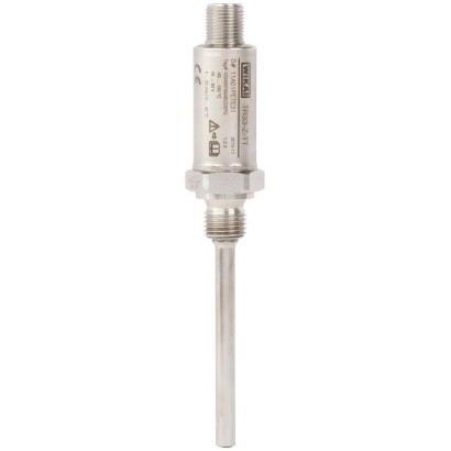
ترمومتر مقاومة مصغّر
الوصف
تُستخدم موازين الحرارة المقاومة من هذه السلاسل كأجهزة قياس حرارة عالمية لقياس وسائط سائلة وغازية في نطاق -50 ... +250 °C [-58 ... +482 °F].
يمكن استخدامها للضغوط حتى 140 bar [2,030 psi] مع أقطار أنابيب الحماية 3 mm [0.12 in] وحتى 270 bar [3,916 psi] مع أقطار أنابيب الحماية 6 mm [0.24 in]، وذلك اعتمادًا على إصدار الجهاز. جميع المكونات الكهربائية محمية ضد الرطوبة (IP67 أو IP69K) ومصممة لتحمّل الاهتزاز (20 g، اعتمادًا على إصدار الجهاز).
يتوفر مقياس الحرارة المقاوم بإخراج مباشر للمستشعر أو مع مرسل مدمج، ويمكن تهيئته بشكل فردي عبر برنامج إعداد WIKAsoft-TT الخاص بالكمبيوتر. يمكن ضبط نطاق القياس، والتخميد، وإشارة الخطأ وفقًا لـ NAMUR NE 043 ورقم الوسم (tag no.).
للموافقات الإضافية، راجع الصفحة 6
الشكل يسارًا: مقياس حرارة مقاوم، الطراز TR33 الشكل يمينًا: محول M12 x 1 إلى موصل زاوي وفق DIN EN 175301-803
يمكن اختيار طول الإدخال، ووصلة العملية، ونوع المستشعر وطريقة التوصيل لكل منها ضمن معلومات الطلب الخاصة بالتطبيق المعني. يتكوّن مقياس الحرارة المقاوم طراز TR33 من أنبوب حماية بوصلة عملية ثابتة ويتم تثبيته باللولب مباشرةً في العملية. يتم إجراء التوصيل الكهربائي عبر موصل دائري M12 x 1. ويتوفر بشكل اختياري محول للتوصيل الكهربائي مع موصل زاوي وفق DIN EN 175301-803 (براءة، حق ملكية صناعية: 001370985).
المزايا
- تصميم مدمج جداً، مقاومة عالية للاهتزاز وزمن استجابة سريع
- مع خرج حساس مباشر (Pt100، Pt1000 بتوصيل سلكي ثنائي أو ثلاثي أو رباعي) أو مرسل مدمج بإشارة خرج 4 ... 20 mA
- مُرسل مدمج قابل للمعايرة الفردية باستخدام برنامج WIKAsoft-TT المجاني لتهيئة الحاسوب
- عنصر المستشعر بفئة دقة A وفق IEC 60751
الأسئلة والأجوبة
ما هو نطاق قياس درجة الحرارة للطراز TR33؟
يمكن قياس وسائط سائلة وغازية في نطاق -50 … +250 °C، وذلك اعتمادًا على إصدار الجهاز.
ما هي دقة المستشعر؟
عنصر المستشعر متوفر بفئتي دقة A وB وفق IEC 60751، وفئة الدقة للمُرسِل هي ±0.25 K.
ما هي وصلات العملية المتوفرة؟
G¼B، G⅜B، G½B، ¼NPT، ½NPT، M12 x 1.5، M20 x 1.5، و7/16-20 UNF-2A.
هل يتحمل الجهاز الاهتزازات؟
نعم، يتميز TR33 بمقاومة عالية للاهتزاز (حتى 20 g اعتمادًا على الإصدار)، وهو مصمم للتطبيقات ذات الاهتزازات العالية مثل الهيدروليكا وتقنيات الدفع.
ما هي إشارات الخرج المتاحة؟
إخراج مباشر للمستشعر Pt100 أو Pt1000 بتوصيل 2 أو 3 أو 4 أسلاك، أو مُرسِل مدمج بإشارة خرج 4 … 20 mA مع دعم HART.
كيف تتم تهيئة المُرسِل المدمج؟
يمكن تهيئته بشكل فردي عبر برنامج WIKAsoft-TT المجاني للكمبيوتر، بما في ذلك ضبط نطاق القياس والتخميد وإشارة الخطأ وفق NAMUR NE 043 ورقم الوسم.
ما هو التوصيل الكهربائي؟
التوصيل الكهربائي يتم عبر موصل دائري M12 x 1 رباعي الأطراف، مع تغذية DC 10 … 30V، ويتوفر اختياريًا محوّل إلى موصل زاوي وفق DIN EN 175301-803.
ما الذي يميز TR33 عن غيره من ترمومترات المقاومة؟
تصميمه المصغّر جدًا بقطر أنبوب حماية 3 mm فقط، مع وصلة عملية ملولبة مثبتة مباشرةً، مما يجعله مناسبًا للأماكن الضيقة والتطبيقات التي تتطلب استجابة سريعة ومقاومة للاهتزاز.
| الطراز | TR33 |
| النوع الفرعي | Resistance thermometer |
| نطاق درجة الحرارة | −50…+250 °C · −30…+250 °C · −20…+125 °C |
| فئة الدقة | ±0.25 K |
| وصلة العملية | G¼BG⅜BG½B¼NPT½NPTM12 x 1.5M20 x 1.57/16-20 UNF-2A |
| درجة حرارة العملية | −50…+250 °C |
| إشارة الخرج | 4-20mA · HART |
| التغذية | DC 10 ... 30V |
| وصلة كهربائية | M12 x 1 circular connector (4-pin) |
| مادة المجس | Stainless steel 1.4571 |
| حرارة المحيط | −40…+85 °C |
| تصنيف IP | IP67 |
| الشهادات | CERoHSREACH |
| نوع المستشعر | Pt100, Pt1000 |
| فئة المستشعر | A, B |
| قطر المجس | 3 mm |
| جراب الحرارة | لا |
| لغات ورقة البيانات | EN, DE |
| Type of measuring element | ||
|---|---|---|
| Version 4 ... 20 mA(modelTR33-Z-TT) | Pt1000 (measuring current < 0.3 mA;self-heating can be ignored) | |
| Version Pt100 (model TR33-Z-Px) / Pt1000 (model TR33-Z-Sx) | ■ Pt100 (measuring current: 0.1 ... 1.0 mA) ■ Pt1000 (measuring current: 0.1 ... 0.3 mA) | |
| → For detailed specifications for Pt sensors, see Technical information IN 00.17 at www.wika.com. | ||
| Connection method | ||
| Version 4 ... 20 mA(modelTR33-Z-TT) | 2-wire | |
| Version Pt100 (model TR33-Z-Px) / Pt1000 (model TR33-Z-Sx) | 2-wire | The lead resistance is recorded as an error in the measurement |
| 3-wire | With a cable length of 30 mor longer, measuring deviations can occur | |
| 4-wire | The lead resistance can be ignored | |
| Tolerance value of the measuring element 1) per IEC 60751 | ||
| Version 4 ... 20 mA(modelTR33-Z-TT) | Class A | |
| Version Pt100 (model TR33-Z-Px) / Pt1000 (model TR33-Z-Sx) | ■ Class A ■ Class B at | 2-wire |
| Tolerance value of the measuring element 1) per IEC 60751 | Class A |
|---|---|
| Measuring deviation of the transmitter per IEC 62828 | ±0.25 K |
| Total measuring deviation per IEC 62828 | Measuring deviation of the measuring element + transmitter |
| Influence of the ambient temperature | 0.1 %of the set measuring span / 10 KT a |
| Influence of supply voltage | ±0.025 %/V(depending on the supply voltage U B ) |
| Influence of the load | ±0.05 %/ 100Ω |
| Linearisation | Linear to temperature per IEC 60751 |
| Output error | ±0.1% 2) |
| Reference conditions | |
| Ambient temperatureT a ref | 23 °C |
| Supply voltage U B ref | DC 12V |
| Temperature range | ||
|---|---|---|
| Version 4 ... 20 mA(modelTR33-Z-TT) | Without neck tube -30 ...+150 °C [-22 ...+302 °F] With neck tube -30 ...+250 °C [-22 ...+482 °F] 1) Version with FKM O-ring: -20 ...+125 °C [-4 ...+257 °F] | |
| Version Pt100 (model TR33-Z-Px) / Pt1000 (model TR33-Z-Sx) | Class A | Without neck tube -30 ...+150 °C [-22 ...+302 °F] With neck tube -30 ...+250 °C [-22 ...+482 °F] Version with FKM O-ring: -20 ...+125 °C [-4 ...+257 °F] |
| Class B | Without neck tube -50 ...+150 °C [-58 ...+302 °F] With neck tube -50 ...+250 °C [-58 ...+482 °F] | |
| Unit (4 ... 20 mA version) | Configurable °C, °F, K | |
| Temperature at the connector (Pt100, Pt1000 version) | Max. 85 °C [185 °F] | |
| Measuring span (4 ... 20 mA version) | Minimum 20 K, maximum 300 K |
| Process connection | |
|---|---|
| Type of process connection | ■ G¼B ■ G⅜B ■ G½B ■ ¼NPT ■ ½NPT ■ M12 x 1.5 ■ M20 x 1.5 ■ 7/16-20 UNF-2A |
| Protection tube | |
| Protection tube diameter | ■ 3 mm[0.12 in] ■ 6 mm[0.24 in] |
| Insertion length U 1 | ■ 50 mm[1.97 in] ■ 75 mm[2.95 in] 1) ■ 100 mm[3.94 in] 1) ■ 120 mm[4.72 in] 1) ■ 150 mm[5.91 in] 1) ■ 200 mm[7.87 in] 1) ■ 250 mm[9.84 in] 1) ■ 300 mm[11.81 in] 1) ■ 350 mm[13.78 in] 1) ■ 400 mm[15.75 in] 1) Other insertion lengths on |
| request | |
| Material (wetted) | Stainless steel 1.4571 |
عرض الكل (14)
| Output signal (4 ... 20 mA version) | |
|---|---|
| Analogue output | 4 ... 20 mA, 2-wire |
| Load R A | R A ≤ (U B - 10 V) / 23 mAwith R A in Ωand U B inV The permissible load depends on the loop supply voltage. For communication with the instrument with programming unit PU-548, a max. load of 350 Ωis admissible. |
| Load diagram | Load R A inΩ Voltage U B inV 0 10 24 30 36 1083 833 583 |
| Factory configuration | |
| Measuring range | Measuring range 0 ... 150 °C [32 ... 302 °F] Other measuring ranges are adjustable |
| Current signals for error signalling | Configurable in accordance with NAMUR NE 043 downscale ≤ 3.6mA upscale ≥ 21.0mA |
| Current value for sensor short-circuit | Not configurable in accordance with NAMUR NE 043 downscale ≤ 3.6mA |
| Communication | |
| Info data | Tag no., description and user message can be stored in transmitter |
| Configuration and calibration data | Permanently stored |
| Configuration software | WIKAsoft-TT → Configuration software (multilingual) as a download from www.wika.com |
| Voltage supply | |
| Supply voltage U B | DC 10 ...30V |
| Supply voltage input | Protected against reverse polarity |
| Permissible residual ripple of supply voltage | 10 %generated by U B < 3 %ripple of the output current |
| Time response | |
| Switch-on delay, electrical | Max. 4 s (time before the first measured value) |
| Warm-up time | After approx. 4 minutes, the instrument will function to the specifications (accuracy) given in the data sheet. |
| Connection type | M12 x 1 circular connector (4-pin) |
|---|---|
| Material | Stainless steel 1.4571 |
| Pin | Signal | Description |
|---|---|---|
| 1 | L+ | 10 ...30V |
| 2 | VQ | not connected |
| 3 | L- | 0V |
| 4 | C | not connected |
| Operating conditions | |
|---|---|
| Ambient temperature range | |
| Version 4 ... 20 mA(modelTR33-Z-TT) | -40 ...+85 °C [-40 ...+185 °F] Version with FKM O-ring: -20 °C [-4 °F] |
| Version Pt100 (model TR33-Z-Px) / Pt1000 (model TR33-Z-Sx) | -50 ...+85 °C [-58 ...+185 °F] Version with FKM O-ring: -20 °C [-4 °F] |
| Storage temperature range | -40 ...+85 °C [-40 ...+185 °F] Version with FKM O-ring: -20 °C [-4 °F] |
| Climate class per IEC 60654-1 | |
| Version 4 ... 20 mA(modelTR33-Z-TT) | Cx (-40 ...+85 °C [-40 ...+185 °F], 5 ... 95 %r.h.) Version with FKM O-ring: -20 °C [-4 °F] |
| Version Pt100 (model TR33-Z-Px) / Pt1000 (model TR33-Z-Sx) | Cx (-50 ...+85 °C [-58 ...+185 °F], 5 ... 95 %r.h.) Version with FKM O-ring: -20 °C [-4 °F] |
| Maximum permissible humidity, condensation | 100 %r.h., condensation allowed |
| Maximum operating pressure 1) 2) | |
| For protection tube diameter 3 mm[0.12 in] | 140 bar [2,030 psi] |
| For protection tube diameter 6 mm[0.24 in] | 270 bar [3,916 psi] |
| Salt fog | IEC 60068-2-11 |
| Vibration resistance per IEC 60751 | 10 ... 2,000 Hz, 20 g 1) |
| Shock resistance per IEC 60068-2-27 | 50 g, 6 ms, 3 axes, 3 directions, three times per direction |
| Maximum permissible autoclaving conditions | Max. 134 °C, 3 bar abs., 100 %r.h., duration 20 min., max. 50 cycles |
| Autoclavable with mounted protective cap at coupler connector | |
| Conditions for outdoor use (only applies to UL approval) | ■ The instrument is suitable for applications with pollution degree 3. ■ The power supply must be suitable for operation above 2,000m should the temperature transmitter be used at this altitude. ■ The instrument shall be installed in locations sheltered from the weather. ■ The instrument shall be installed sun/UV irradiation protected. |
| Ingress protection (IP code) | |
|---|---|
| Case with connected connector 3) | ■ IP67 per IEC/EN 60529 ■ IP69 per IEC/EN 60529 ■ IP69K per ISO 20653 |
| Coupler connector, not connected | IP67 per IEC/EN 60529 |
| Weight | approx. 0.2 ... 0.7 kg [0.44 ... 1.54 lbs] - depending on version |
| Logo | Description | Country |
|---|---|---|
| EU declaration of conformity | European Union | |
| CSA Safety (e.g. electr. safety, overpressure, ...) | USA and Canada | |
| UL Safety (e.g. electr. safety, overpressure, ...) | USA and Canada |
| Logo | Description | Country |
|---|---|---|
| EAC EMCdirective 1) | Eurasian Economic Community | |
| GOST Metrology, measurement technology | Russia | |
| KazInMetr Metrology, measurement technology | Kazakhstan | |
| - | MTSCHS Permission for commissioning | Kazakhstan |
| BelGIM Metrology, measurement technology | Belarus | |
| UkrSEPRO Metrology, measurement technology | Ukraine | |
| Uzstandard Metrology, measurement technology | Uzbekistan |
| Certification type | Measurement accuracy | Material certificate |
|---|---|---|
| 2.2 test report | x | x |
| 3.1 inspection certificate | x | x |
| DKD/DAkkS calibration certificate | x | - |
| Model | Description | Order no. | |
|---|---|---|---|
| Programming unit Model PU-548 | ■ Easy to use ■ LED status display ■ Compact design ■ No further voltage supply needed, neither for the programming unit nor for the transmitter | 14231581 | |
| Adapter cable M12 to PU-548 | Adapter cable for the connection of a modelTR33 resistance thermometer to the model PU-548 programming unit | 14003193 | |
| M12 x 1 transmitter adapter to DIN EN 175301-803 angular connector (yellow female connector element) | Adapter for the connection of a resistance thermometer with a DIN EN 175301-803 angular connector form A with a 4 ... 20 mAoutput signal → see data sheet AC 80.17 Case: PA Ambient temperature: -40 ...+115 °C [-40 ...+239 °F] Union nut: Zinc die-cast Contacts: Copper-zinc alloy, tinned Dielectric strength: 500V Ingress protection: IP65 4 ...20mA M12 x 1 connector Angular connector | 14069503 | |
| M12 x 1 Pt adapter to DIN EN 175301-803 angular connector (black female connector element) | Adapter for the connection of the resistance thermometer with a DIN EN 175301-803 form A angular connector with direct resistance output signal → see data sheet AC 80.17 Case: PA Ambient temperature: -40 ...+115 °C [-40 ...+239 °F] Union nut: Zinc die-cast Contacts: Copper-zinc alloy, tinned Dielectric strength: 500V Ingress protection: IP65 mA 4 ...20mA M12 x 1 connector Angular connector | 14061115 | |
| Angular connector | Per DIN EN 175301-803 form A | 11427567 | |
| Sealing for angular connector | For use with angular connector DIN EN 175301-803-A EPDM, brown | 11437902 |
| Model | Description | Order no. | ||
|---|---|---|---|---|
| - | M12 connection cable | Cable socket straight, 4-pin, ingress protection IP67 Temperature range -20 ...+80 °C [-4 ...+176 °F] | Cable length2m [6.56 ft] | 14086880 |
| Cable length5m [16.40 ft] | 14086883 | |||
| Cable socket straight, 4-pin, ingress protection IP69K, hygienic design Union nut from stainless steel Temperature range -40 ...+80 °C [-40 ...+176 °F] | Cable length3m [9.84 ft] | 14137167 | ||
| Cable length5m [16.40 ft] | 14137168 | |||
| Angled socket, 4-pin, ingress protection IP67 Temperature range -20 ...+80 °C [-4 ...+176 °F] | Cable length2m [6.56 ft] | 14086889 | ||
| Cable length5m [16.40 ft] | 14086891 | |||
| Angled socket, 4-pin, ingress protection IP69K, hygienic design Union nut from stainless steel Temperature range -40 ...+80 °C [-40 ...+176 °F] | Cable length3m [9.84 ft] | 14137169 | ||
| Cable length5m [16.40 ft] | 14137170 | |||
| - | M12 connector | Female angled, 4-pin, ingress protection IP67 Screw connection for conductor cross-section 0.25 …0.75 mm² [24 …18 AWG] Cable gland Pg7, outside diameter of cable 4 …6mm[0.16 ... 0.24 in] | 14136815 |
لم تجد الإجابة في الوثائق؟ سيرد المهندس خلال يوم عمل.
اسأل المهندس →80 مادة قياسية من عائلة TR33
إذا كنت تعرف الرمز — اختر مباشرة. إذا لا — استخدم المُهيِّئ في الوضع «01».