
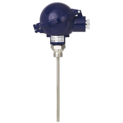
ترموكبل
الوصف
الترموقترنات (Thermocouples) بدون غلاف حراري (thermowell) مناسبة بشكل خاص للتطبيقات التي يتم فيها تركيب طرف المستشعر المعدني مباشرةً داخل ثقوب مثقوبة (مثلًا في أجزاء الماكينات) أو مباشرةً داخل العملية لأي تطبيق لا يتضمن وسائط كيميائية عدوانية أو تآكل/احتكاك.
للتثبيت داخل غلاف حراري (thermowell)، ينبغي توفير وصلة ضغط مزوّدة بنابض (spring-loaded compression fitting)، لأن هذا فقط هو الذي يمكنه دفع طرف القياس إلى قاع الغلاف الحراري. وإلا فقد يتم تطبيق قوة — قد تكون حرجة — على طرف القياس. يتم عادةً إجراء التركيب مباشرةً داخل العملية. ويمكن أيضًا استخدام عناصر تثبيت مثل الوصلات الملولبة، أو صواميل الاتحاد (union nuts)، إلخ.
للموافقات الإضافية، راجع الصفحة 2
الشكل يسارًا: الطراز TC10-H مع رأس توصيل BSZ الشكل يمينًا: الطراز TC10-H مع رأس توصيل JS
الجزء المرن من المجس عبارة عن كابل مُعزَّز بالمعادن (mineral-insulated cable) (كابل مُغلف). ويتكوّن من غلاف خارجي من الفولاذ المقاوم للصدأ يحتوي على التوصيلات الداخلية المعزولة، ومُضمَّن داخل مركّب سيراميكي عالي الكثافة، وهو مناسب أيضًا للاستخدام عند درجات حرارة أعلى.
وبشكل اختياري يمكننا تركيب مرسلات تماثلية أو رقمية من نطاق WIKA داخل رأس التوصيل الخاص بـ TC10-H.
المزايا
- مدى المستشعر من -40 ... +1,200 °C [-40 ... + 2,192 °F]
- للإدخال والتثبيت اللولبي مع وصلة عملية اختيارية
- رأس توصيل شكل B أو JS
- تتوفر نسخ مقاومة للانفجار لعدة أنواع من الموافقات (انظر صفحة 2 من ورقة البيانات)
الأسئلة والأجوبة
ما هو نطاق القياس لهذا الترموكبل؟
يقيس المستشعر في نطاق من -40 … +1,200 °C [-40 … +2,192 °F]، ونطاق درجة الحرارة المحيطة هو -40 … +80 °C.
ما أنواع المزدوجات الحرارية وفئات الدقة المتوفرة؟
يتوفر بأنواع K/J/E/N/T وبفئتي Class 1 وClass 2.
هل يحتوي هذا الطراز على غلاف حراري؟
لا، إنه ترموكبل بدون غلاف حراري (thermowell) مصمم للتركيب المباشر في العملية. عند التثبيت داخل غلاف حراري، يجب استخدام وصلة ضغط مزوّدة بنابض لدفع طرف القياس إلى قاع الغلاف.
ما هي وصلات العملية المتوفرة؟
بدون وصلة عملية (بما فيها النسخة المصغرة)، لولب ثابت بارز، وصلة ضغط، وصلة ضغط مزوّدة بنابض، وصامولة سداسية ملولبة مزدوجة.
هل تتوفر نسخ محمية ضد الانفجار؟
نعم، تتوفر إصدارات محمية ضد الانفجار لأنواع موافقات عديدة مثل ATEX وIECEx (مثل Ex ia IIC T1 ~ T6 Ga/Gb/Gc وEx eb IIC T1 ~ T6 Gb) — انظر صفحة 2 من ورقة البيانات.
هل يدعم خرج HART؟
نعم، إشارة الخرج هي 4-20mA مع دعم HART عبر مرسل اختياري يُركَّب داخل رأس التوصيل، ويمكن تحقيق SIL 2 (وفق IEC 61508 / IEC 61511) باستخدام مرسل الطراز T32.
من أي مواد يُصنع مجس المستشعر؟
الجزء المرن كابل معزّز بالمعادن بغلاف خارجي من الفولاذ المقاوم للصدأ (Stainless steel) أو Alloy 600، بقطر 3.0 mm، ومضمَّن بمركّب سيراميكي عالي الكثافة مناسب لدرجات الحرارة المرتفعة.
ما الذي يميز TC10-H عن طرازات أخرى؟
إنه مخصص للتركيب المباشر دون غلاف حراري، مع رأس توصيل الشكل B أو JS، وخيارات واسعة لوصلات العملية والموافقات ضد الانفجار.
| الطراز | TC10-H |
| السلسلة | TC10 |
| النوع الفرعي | Sheathed thermocouple |
| نطاق درجة الحرارة | −40…+1200 °C |
| مستوى السلامة الوظيفية (SIL) | SIL 2 (IEC 61508 / IEC 61511) with transmitter model T32 |
| وصلة العملية | Without process connectionWithout process connection (miniature version)Protruded fixed threadCompression fittingSpring-loaded compression fittingDouble threaded hex bushing |
| درجة حرارة العملية | −40…+1200 °C |
| إشارة الخرج | 4-20mA · HART |
| التغذية | Required for transmitter with display (e.g. DIH10) |
| وصلة كهربائية | Connection head form B or JS |
| مادة المجس | Alloy 600, Stainless steel |
| حرارة المحيط | −40…+80 °C |
| تصنيف IP | IP65 |
| الشهادات | RoHSATEXIECExEACINMETROCCCKCs-KOSHAPESOGOSTKazInMetrMTSCHSBelGIMUkrSEPROUzstandardCEEx UkraineREACH |
| حماية الانفجار | 0Ex ia IIC T3/T4/T5/T6Ex ia IIC T1 ~ T6 GaEx ia IIC T1 ~ T6 GbEx ic IIC T1 ~ T6 GcEx iaD 20 T65/T95/T125°CEx iaD 21 T65/T95/T125°CEx eb IIC T1 ~ T6 GbEx ec IIC T1 ~ T6 GcEx nA IIC T1 ~ T6 GcII 1G Ex ia IIC T1 ... T6 GaII 2G Ex ia IIC T1 ... T6 GbII 1D Ex ia IIIC T125 ... T65 °C DaII 2D Ex ia IIIC T125 ... T65 °C DbII 2G Ex eb IIC T1…T6 GbII 3G Ex ec IIC T1…T6 GcII 2D Ex tb IIIC TX °C DbII 3D Ex tc IIIC TX °C DcII 3G Ex nA IIC T1 ... T6 Gc XII 3D Ex tc IIIC T440 ... T80 °C Dc XEx ia IIC T1 ... T6 GaEx ia IIC T1 ... T6 GbEx ia IIIC T125 ... T65 °C DaEx ia IIIC T125 ... T65 °C Db1Ex ib IIC T3/T4/T5/T6DIP A20 Ta 65 °C/Ta 95 °C/Ta 125 °CDIP A21 Ta 65 °C/Ta 95 °C/Ta 125 °C2Ex nA IIC T6 ... T1 Gc XEx ia IIIC T65°C DaEx ia IIIC T65°C DbEx ia IIC T3 ... T6 GaEx ia IIC T3 ... T6 GbEx ia IIC T4 ... T6Ex ib IIC T4 ... T6ExiaIICT125...T65℃DaExiaIICT125...T65℃DbExebIICT1...T6GbExecIICT1...T6GcExnAIICT1...T6GcXExiaIICT65℃DaExiaIICT65℃DbExiaD20T65/T95/T125℃ExiaD21T65/T95/T125℃ |
| نوع المستشعر | Type K/J/E/N/T |
| فئة المستشعر | Class 1, Class 2 |
| قطر المجس | 3 mm |
| جراب الحرارة | لا |
| لغات ورقة البيانات | EN, DE |
| Logo | Description | Country | |
|---|---|---|---|
| EU declaration of conformity ■ EMCdirective 1) | European Union | ||
| ■ ATEX directive (option) Hazardous areas - Ex i Zone 0 gas Zone 1 gas Zone 20 dust Zone 21 dust - Ex e 2) Zone 1 gas Zone 2 gas Zone 21 dust Zone 22 dust - Ex n 2) Zone 2 gas Zone 22 dust IECEx (option) - in conjunction with ATEX Hazardous areas | II 1G Ex ia IIC T1 ...T6 Ga II 2G Ex ia IIC T1 ...T6 Gb II 1D Ex ia IIIC T125 ...T65 °C Da II 2D Ex ia IIIC T125 ...T65 °C Db II 2G Ex eb IICT1…T6 Gb 3) 4) II 3G Ex ec IICT1…T6 Gc II 2D Ex tb IIICTX °C Db 3) 4) II 3D Ex tc IIICTX °C Dc II 3G Ex nA IIC T1 ...T6 Gc X II 3D Ex tc IIIC T440 ...T80 °C Dc X | International | |
| EAC (option) Hazardous areas Ex i Zone 0 gas 0Ex ia IIC T3/T4/T5/T6 | Eurasian Economic Community | ||
| Zone 21 dust - Ex n 2) Zone 2 Gas Ex Ukraine (option) Hazardous areas - Ex i Zone 0 gas Zone 1 gas | DIP A21Ta 65 °C/Ta 95 °C/Ta 125 °C 2Ex nA IIC T6 ...T1 Gc X II 1G Ex ia IIC T1...T6 Ga | Ukraine | |
| Zone 20 dust Zone 21 dust | |||
| (option) areas - Ex Zone 0 gas Zone 20 dust | Ex ia IIC T3 ...T6 Ga Ex ia IIIC T125 ...T65 °C Da | Brazil | |
| INMETRO Hazardous i |
| Logo | Description | Country | |
|---|---|---|---|
| CCC (option) 4) Hazardous areas | China | ||
| - Ex i Zone 0 gas Zone 1 gas Zone 2 gas Zone 20 dust Zone 21 dust - Ex e 2) Zone 1 gas Zone 2 gas - Ex n 2) Zone 2 gas | Ex ia IIC T1 ~ T6 Ga Ex ia IIC T1 ~ T6 Gb Ex ic IIC T1 ~ T6 Gc Ex iaD 20 T65/T95/T125°C Ex iaD 21 T65/T95/T125°C Ex eb IIC T1 ~ T6 Gb 3) 4) Ex ec IIC T1 ~ T6 Gc Ex nA IIC T1 ~ T6 Gc | ||
| - | KCs - KOSHA (option) Hazardous areas - Ex i Zone 0 gas Ex ia IIC T4 ...T6 Zone 1 gas Ex ib IIC T4 ...T6 (option) areas Ex i Zone 0 gas Ex ia IIC T1 ...T6 Ga | India | |
| PESO Hazardous - Zone 1 gas Ex ia IIC T1 ...T6 Gb | Russia | ||
| GOST (option) Metrology, measurement technology | Kazakhstan | ||
| KazInMetr (option) Metrology, measurement technology | |||
| - | MTSCHS (option) Permission for commissioning | Kazakhstan Belarus | |
| BelGIM (option) Metrology, measurement technology | |||
| UkrSEPRO (option) Metrology, measurement technology | Ukraine |
| Type | Validity limits of class accuracy | ||
|---|---|---|---|
| IEC 60584-1 | ASTM E230 | ||
| Class 2 | Class 1 | Standard Special | |
| K | -40 ... +1,200 °C | -40 ... +1,000 °C | 0 ... 1,260 °C |
| J | -40 ...+750 °C | -40 ...+750 °C | 0 ... 760 °C |
| E | -40 ...+900 °C | -40 ...+800 °C | 0 ... 870 °C |
| N | -40 ... +1,200 °C | -40 ... +1,000 °C | 0 ... 1,260 °C |
| T | -40 ...+350 °C | 0 ... 370 °C |
| Model | Material | Cable entry thread size | Ingress protection (max.) 1) IEC/EN 60529 | Cap | Surface | Connection to neck tube |
|---|---|---|---|---|---|---|
| JS | Aluminium | M16 x 1.5 3) | IP65 | Cover with 2 screws | Blue, lacquered 5) | M24 x 1.5,½NPT |
| BS | Aluminium | M20 x 1.5 or½NPT 3) | IP65 4) | Flat cap with 2 screws | Blue, lacquered 5) | M24 x 1.5,½NPT |
| BSZ | Aluminium | M20 x 1.5 or½NPT 3) | IP65 4) | Spherical hinged cover with cylinder head screw | Blue, lacquered 5) | M24 x 1.5,½NPT |
| BSZ-H | Aluminium | M20 x 1.5 or½NPT 3) | IP65 4) | Raised hinged cover with cylinder head screw | Blue, lacquered 5) | M24 x 1.5,½NPT |
| BSZ-H (2x cable outlet) | Aluminium | 2 x M20 x 1.5 or 2x½NPT 3) | IP65 4) | Raised hinged cover with cylinder head screw | Blue, lacquered 5) | M24 x 1.5 |
| BSZ-H / DIH10 2) | Aluminium | M20 x 1.5 or½NPT 3) | IP65 | Raised hinged cover with cylinder head screw | Blue, lacquered 5) | M24 x 1.5,½NPT |
| BSS | Aluminium | M20 x 1.5 or½NPT 3) | IP65 | Spherical hinged cover with clamping lever | Blue, lacquered 5) | M24 x 1.5,½NPT |
| BSS-H | Aluminium | M20 x 1.5 or½NPT 3) | IP65 | Raised hinged cover with clamping lever | Blue, lacquered 5) | M24 x 1.5,½NPT |
| BVS | Stainless steel | M20 x 1.5 3) | IP65 | Precision-cast screw- on lid | Blank, electropolished | M24 x 1.5 |
| BSZ-K | Plastic | M20 x 1.5 or½NPT 3) | IP65 | Spherical hinged cover with cylinder head screw | Black | M24 x 1.5 |
| BSZ-HK | Plastic | M20 x 1.5 or½NPT 3) | IP65 | Raised hinged cover with cylinder head screw | Black | M24 x 1.5 |
عرض الكل (17)
| Model | Explosion protection | |||||
|---|---|---|---|---|---|---|
| Without | Ex i (gas) Zone 0, 1, 2 | Ex i (dust) Zone 20, 21, 22 | Ex e (gas) Zone 1, 2 | Ex t (dust) Zone 21, 22 | Ex nA (gas) Zone 2 | |
| JS | x | x | x | - | - | - |
| BS | x | x | x | - | - | - |
| BSZ | x | x | x | x 6) | x 6) | x 7) |
| BSZ-H | x | x | x | x 6) | x 6) | x 7) |
| BSZ-H (2x cable outlet) | x | x | x | x 6) | x 6) | x 7) |
| BSZ-H / DIH10 2) | x | x | - | - | - | - |
| BSS | x | x | - | - | - | - |
| BSS-H | x | x | - | - | - | - |
| BVS | x | x | - | - | - | - |
| BSZ-K | x | x | - | - | - | - |
| BSZ-HK | x | x | - | - | - | - |
| Cable entry | Cable entry thread size | Min./max. ambient temperature |
|---|---|---|
| Standard cable entry 1) | M20 x 1.5 or½NPT | -40 ...+80 °C |
| Plastic cable gland (cable Ø 6 ... 10 mm) 1) | M20 x 1.5 or½NPT | -40 ...+80 °C |
| Plastic cable gland (cable Ø 6 ... 10 mm), Ex e 1) | M20 x 1.5 or½NPT | -20 ...+80 °C (standard) -40 ...+70 °C (option) |
| Nickel-plated brass cable gland (cable Ø 6 ... 12 mm) | M20 x 1.5 or½NPT | -60 2) / -40 ...+80 °C |
| Cable entry | Colour | Ingress protection (max.) 3) | Explosion protection | |||||
|---|---|---|---|---|---|---|---|---|
| IEC/EN 60529 | without | Ex i (gas) Zone 0, 1, 2 | Ex i (dust) Zone 20, 21, 22 | Ex e (gas) Zone 1, 2 | Ex t (dust) Zone 21, 22 | Ex nA (gas) Zone 2 | ||
| Standard cable entry 1) | Blank | IP65 | x | x | - | - | - | - |
| Plastic cable gland 1) | Black or grey | IP66 4) | x | x | - | - | - | - |
| Plastic cable gland, Ex e 1) | Light blue | IP66 4) | x | x | x | - | - | - |
| Plastic cable gland, Ex e 1) | Black | IP66 4) | x | x | x | x | x | x |
| Nickel-plated brass cable gland | Blank | IP66 4) | x | x | x | - | - | - |
| Nickel-plated brass cable gland, Ex e | Blank | IP66 4) | x | x | x | x | x | x |
| First index number | Degree of protection / short description | Test parameter |
|---|---|---|
| 5 | Dust-protected | per IEC/EN 60529 |
| 6 | Dust-tight | per IEC/EN 60529 |
| Second index number | Degree of protection / short description | Test parameter |
|---|---|---|
| 4 | Protected against splash water | per IEC/EN 60529 |
| 5 | Protected against water jets | per IEC/EN 60529 |
| 6 | Protected against strong water jets | per IEC/EN 60529 |
| 7 1) | Protected against the effects of temporary immersion in water | per IEC/EN 60529 |
| 8 1) | Protected against the effects of continuous immersion in water | by agreement |
| Transmitter (selectable versions) | Model T16 | Model T32 | Model T91.20 |
|---|---|---|---|
| Data sheet | TE 16.01 | TE 32.04 | TE 91.01 |
| Output | |||
| 4 ...20mA | x | x | x |
| HART ® protocol | - | x | - |
| Input | |||
| Thermocouples IEC 60584-1 | K, J, E, N,T | K, J, E, N,T | K, J,T |
| Explosion protection | Optional | Optional | - |
| Connection head | T16 | T32 | T91.20 |
|---|---|---|---|
| JS | - | - | ○ |
| BS | ○ | - | - |
| BSZ, BSZ-K | ○ | ○ | - |
| BSZ-H, BSZ-HK | ● | ● | - |
| BSZ-H (2x cable outlet) | ● | ● | - |
| BSZ-H / DIH10 | ○ | ○ | - |
| BSS | ○ | ○ | - |
| BSS-H | ● | ● | - |
| BVS | ○ | ○ | - |
| Certification type | Measurement accuracy | Material certificate |
|---|---|---|
| 2.2 test report | x | x |
| 3.1 inspection certificate | x | x |
| DKD/DAkkS calibration certificate | x | - |
| Thermometer description | RTD | Data sheet | TC | Data sheet |
|---|---|---|---|---|
| For additional thermowell | TR10-B | TE 60.02 | TC10-B | TE 65.02 |
| Process version | TR12-B | TE 60.17 | TC12-B | TE 65.17 |
| Cable thermometers | TR40 | TE 60.40 | TC40 | TE 65.40 |
| Threaded thermometer | TR10-C | TE 60.03 | TC10-C | TE 65.03 |
| Flanged resistance thermometer | TR10-F | TE 60.06 | TC10-F | TE 65.06 |
| Operation without thermowell | TR10-H | TE 60.08 | TC10-H | TE 65.08 |
| Connection method | ||
|---|---|---|
| Single element | ■ Pt1000, 1 x 4-wire ■ Thermocouple type E | |
| Validity limits of the class accuracy per EN 60751 | ||
| Pt1000 (cryogenic design) | ±3 K 1) | -253 ... -200 °C [-423 ... -328 °F] |
| Class B | -200 ...+50 °C [-432 ...+122 °F] 2) | |
| Validity limits of the class accuracy in accordance with IEC 60584-1 | ||
| Type E (cryogenic design) | ±3 K 1) | -253 ... -200 °C [-423 ... -328 °F] |
| Class 3 | -200 ... -40 °C [-328 ... -40 °F] | |
| Class 1 | -40 ...+250 °C [-40 ...+482 °F] |
| Diameter ∅din mm[in] | Code number per DIN 43735 | Tolerance in mm | Sheath material | |
|---|---|---|---|---|
| Standard design | Recessed soldering lugs | |||
| 3 [0.12] | - | 3 0 -0.5 | Stainless steel 1.4571 | Stainless steel 1.4571 |
| 6 [0.24] | 60 | 6 0 -0.1 | ■ Stainless steel 1.4571 ■ Stainless steel 316L | Stainless steel 1.4571 |
| 6 [0.24 in] with sleeve | - | 6 0 -0.1 | Stainless steel 1.4571 | Stainless steel 1.4571 |
| 8 [0.31] | - | 8 0 -0.1 | Stainless steel 1.4571 | Stainless steel 1.4571 |
| Measuring insert diameter ∅din mm[in] | Code number per DIN 43735 | Tolerance inmm | Sheath material |
|---|---|---|---|
| 1.5 [0.06] | - | 1.5 ±1% | Stainless steel: 1.4571 |
| 3 [0.12] | 30 | 3 0 -0.5 | Ni alloy: Alloy 600 |
| 6 [0.24] | 60 | 6 0 -0.1 | |
| 6 [0.24] with sleeve | - | 8 0 -0.1 | Ni alloy: Alloy 600 |
| 8 [0.31] | 80 | 8 0 -0.1 | Ni alloy: Alloy 600 |
| Model | Data sheet | Representation |
|---|---|---|
| TW10 | TW95.10 | |
| TW15 | TW95.15 | |
| TW20 | TW95.20 | |
| TW25 | TW95.25 | |
| TW30 | TW95.30 | |
| TW45 | TW95.45 | |
| TW50 | TW95.50 | |
| TW55 | TW95.55 |
لم تجد الإجابة في الوثائق؟ سيرد المهندس خلال يوم عمل.
اسأل المهندس →