
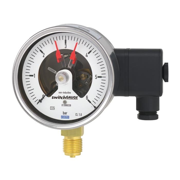
مقياس ضغط أنبوب بورَدون مع نقاط تلامس/مفاتيح
الوصف
حيثما يلزم بيان ضغط العملية محليًا وفي الوقت نفسه يلزم تبديل الدوائر، فإن مقياس التبديل switchGAUGE لطراز PGS21.1x0 يُستخدم لهذا الغرض.
تقوم جهات التلامس الخاصة بالمفتاح (جهات تلامس إنذار كهربائية) بفتح أو إغلاق الدوائر اعتمادًا على وضع مؤشر أداة القياس الدالة على القياس. يمكن ضبط جهات التلامس الخاصة بالمفتاح على كامل مدى نطاق السلم (انظر DIN 16085)، ويتم تركيبها بشكل أساسي أسفل وجه الساعة، على الرغم من أنها قد تكون أيضًا جزئيًا فوق وجه الساعة. يتحرك مؤشر الجهاز (مؤشر القيمة الفعلية) بحرية عبر كامل مدى السلم، دون أن يتأثر بإعدادات الضبط.
يمكن ضبط المؤشر المُعدَّ مسبقًا باستخدام مفتاح ضبط قابل للإزالة عبر النافذة.
للموافقات الإضافية، راجع الصفحة 7
طراز PGS21.100 مع جهات تلامس المفتاح لطراز 821.21
يمكن أيضًا ضبط جهات تلامس المفتاح المكوّنة من عدة جهات لتعمل عند نقطة ضبط واحدة. يتم تفعيل جهة التلامس عندما ينتقل مؤشر القيمة الفعلية إلى ما يتجاوز أو إلى ما دون نقطة الضبط المرغوبة.
يُصنَّع مقياس الضغط وفقًا لـ DIN 16085 ويستوفي جميع متطلبات المعايير ذات الصلة (EN 837-1) واللوائح الخاصة بالعرض الميداني للضغط العامل لأوعية الضغط.
كجهات تلامس للمفتاح، تتوفر جهات تلامس زنبركية مغناطيسية بنظام القَفْز (snap-action)، ومفاتيح القصب (reed switches)، وجهات تلامس إلكترونية. ولتفعيل وحدات التحكم المنطقي القابلة للبرمجة (PLC)، يمكن استخدام الجهات التلامسية الإلكترونية ومفاتيح القصب.
المزايا
- موثوقية عالية وعمر تشغيلي طويل
- حتى 3 تلامسات تبديل لكل جهاز
- أجهزة بنقاط اتصال إلكترونية لتطبيقات PLC
- مقاييس الضغط ذات الملامسات مطابقة لـ DIN 16085
الأسئلة والأجوبة
ما هو نطاق قياس الضغط لهذا المقياس؟
يتوفر الطراز بنطاقات تبدأ من 0 … 0.6 bar وحتى 0 … 600 bar (أو ما يعادلها بالـ psi).
ما هي دقة القياس؟
الصنف 1.0 وفق المعيار EN 837-1.
ما هي وصلات العملية المتاحة؟
M20 x 1.5، G ½ B، و½ NPT.
ما الوسائط التي يناسبها هذا المقياس؟
الوسائط الغازية والسائلة غير عالية اللزوجة وغير المتبلورة، والتي لا تهاجم أجزاء سبيكة النحاس؛ الأجزاء الملامسة للوسط متوفرة بسبيكة نحاس أو فولاذ مقاوم للصدأ 316L.
ما هي حدود درجات الحرارة المسموحة؟
درجة حرارة البيئة المحيطة: -20 … +60 °C، ودرجة حرارة الوسط: -20 … +80 °C.
ما هي درجة الحماية من الدخول؟
IP54.
كم عدد جهات التلامس وما وظائفها؟
حتى 3 جهات تلامس لكل جهاز، بوظائف: فتح عادي، إغلاق عادي، وتحويل (change-over).
كيف يُوصَّل الجهاز كهربائيًا؟
عبر مقبس كابل من PA 6 أسود وفق VDE 0110 (مجموعة عزل C/250 V) مع كابل gland بحجم M20 x 1.5، وبجهد تغذية DC 10 ... 30 V.
| الطراز | PGS21.100 |
| السلسلة | PGS21 |
| النوع الفرعي | Switch gauge with electrical contacts |
| نطاق الضغط | 0…0.6 bar · 0…600 bar · 0…8.7 psi · 0…8702.26 psi |
| فئة الدقة | 1.0 |
| معيار الدقة | EN 837-1 |
| وصلة العملية | M20 x 1.5G ½ B½ NPTG1/2B1/2NPT |
| درجة حرارة العملية | −20…+80 °C |
| إشارة الخرج | PNP transistor · 4-20mA |
| التغذية | DC 10 ... 30 V |
| وصلة كهربائية | Cable socket PA 6, black Per VDE 0110 insulation group C/250 V, Cable gland M20 x 1.5 |
| وظيفة التبديل | Normally open, normally closed, change-over |
| نقاط التبديل | 3 |
| مادة العلبة | Stainless steel |
| مادة الأجزاء الملامسة | Copper alloy, Stainless steel 316L |
| حرارة المحيط | −20…+60 °C |
| تصنيف IP | IP54 |
| الشهادات | CE |
| قطر القرص | 100 mm |
| لغات ورقة البيانات | EN, DE |
| Standard version | |
|---|---|
| Nominal size inmm | ■ 100 ■ 160 |
| Accuracy class | 1.0 |
| Scale ranges | 0 ... 0.6 bar [0 ... 8.7 psi] to 0 ... 600 bar [0 ... 8,702.26 psi] other units (e.g. psi, kPa) available or all other equivalent vacuum or combined pressure and vacuum ranges |
| Scale | ■ Single scale ■ Dual scale |
| Pressure limitation | |
| Steady | Full scale value |
| Fluctuating | 0.9 x full scale value |
| Short time | 1.3 x full scale value |
| Connection location | ■ Lower mount (radial) ■ Lower back mount |
| Process connection (copper alloy) | ■ G½B ■ ½NPT ■ M20 x 1.5 others on request |
| Permissible temperature | |
| Medium | +80 °C [+176 °F] Higher medium temperature on request |
| Ambient | -20 ...+60 °C [-4 ...+140 °F] |
| Temperature effect | When the temperature of the measuring system deviates from the reference temperature (+20 °C): max. ±0.4 %/10 K of full scale value |
| Case | Stainless steel |
| Case filling | Without |
| Wetted materials | |
| Process connection, pressure element | < 100 bar: Copper alloy, trumpet form ≥ 100 bar: Stainless steel 316L, helical type |
| Non-wetted materials | |
| Case, bayonet ring | Stainless steel |
| Movement | Copper alloy, wear parts argentan |
| Dial | Aluminium, white, black lettering |
| Instrument pointer | Aluminium, black |
| Set pointer | Aluminium, red |
| Window | ■ Polycarbonate ■ Laminated safety glass |
| Ingress protection per IEC/EN 60529 | IP54 |
| Electrical connection | Cable socket PA 6, black PerVDE 0110 insulation group C/250V Cable gland M20 x 1.5 Strain relief 6 screw terminals + PE for conductor cross-section 2.5 mm² For dimensions see page 9 others on request |
| Measuring span | Nominal size | Max. number of contacts | Switching current range I | Switch version 1) |
|---|---|---|---|---|
| ≤ 1.0 bar | 100, 160 | 1 | 0.02 ... 0.3 A | L |
| > 1.0 bar | 100, 160 | 1 | 0.02 ... 0.6 A | S |
| ≤ 1.6 bar | 100, 160 | 2 | 0.02 ... 0.3 A | L |
| > 1.6 bar | 100, 160 | 2 | 0.02 ... 0.6 A | S |
| ≤ 4.0 bar | 100 | 3 | 0.02 ... 0.3 A | L |
| > 4.0 bar | 100 | 3 | 0.02 ... 0.6 A | S |
| ≤ 2.5 bar | 160 | 3 | 0.02 ... 0.3 A | L |
| > 2.5 bar | 160 | 3 | 0.02 ... 0.6 A | S |
| Characteristics | Unfilled instruments | Filled instruments | ||
|---|---|---|---|---|
| Resistive load | Resistive load | |||
| Switch version 'S' | Switch version 'L' | Switch version 'S' | Switch version 'L' | |
| Rated operating voltage U eff | ≤ 250V | ≤ 250V | ||
| Rated operating current | ||||
| Switch-on current | ≤ 1.0 A | ≤ 0.5 A | ≤ 1.0 A | ≤ 0.5 A |
| Switch-off current | ≤ 1.0 A | ≤ 0.5 A | ≤ 1.0 A | ≤ 0.5 A |
| Continuous current | ≤ 0.6 A | ≤ 0.3 A | ≤ 0.6 A | ≤ 0.3 A |
| Switching power | ≤ 30W/ ≤ 50VA | ≤ 20W/ ≤ 20VA |
| Operating voltage | Unfilled instruments | Filled instruments | ||||
|---|---|---|---|---|---|---|
| Resistive load | Inductive load | Resistive load | Inductive load | |||
| Direct current | Alter- nating current | cos ϕ>0.7 | Direct current | Alter- nating current | cos ϕ>0.7 | |
| DC 220 V / AC 230 V | 100mA | 120mA | 65mA | 65mA | 90mA | 40mA |
| DC 110 V / AC 110 V | 200mA | 240mA | 130mA | 130mA | 180mA | 85mA |
| DC 48 V / AC 48 V | 300mA | 450mA | 200mA | 190mA | 330mA | 130mA |
| DC 24 V / AC 24 V | 400mA | 600mA | 250mA | 250mA | 450mA | 150mA |
عرض الكل (19)
| Measuring span | Nominal size | Max. number of contacts |
|---|---|---|
| 0.6 bar | 100, 160 | 1 |
| 1.0 bar | 100, 160 | 2 |
| ≥ 1.6 bar | 100, 160 | 2 |
| Contact version | Normally open, normally closed |
|---|---|
| Type of output | PNP transistor |
| Operating voltage | DC 10 ...30V |
| Residual ripple | max.10% |
| No-load current | ≤ 10mA |
| Switching current | ≤ 100mA |
| Residual current | ≤ 100 µA |
| Voltage drop (with I max. ) | ≤ 0.7V |
| Reverse polarity protection | Conditional U B (the switched output 3 or 4 must never be set directly to minus) |
| Anti-inductive protection | 1 kV, 0.1 ms, 1 kΩ |
| Oscillator frequency | approx. 1,000 kHz |
| EMC | per EN 60947-5-2 |
| Measuring span | Nominal size | Max. number of contacts |
|---|---|---|
| ≥ 1.0 bar | 100, 160 | 1 |
| ≥ 1.6 bar | 100, 160 | 2 |
| Characteristics | |
|---|---|
| Contact version | Change-over contact |
| Type of contact | Bistable |
| Max. switching voltage | AC/DC 250V |
| Min. switching voltage | Not required |
| Switching current | AC/DC 1 A |
| Min. switching current | Not required |
| Transport current | AC/DC 2 A |
| cosϕ | 1 |
| Switching power | 60W/VA |
| Contact resistance (static) | 100mΩ |
| Insulation resistance | 10 9 Ω |
| Breakdown voltage | DC 1,000V |
| Switching time incl. contact chatter | 4.5 ms |
| Contact material | Rhodium |
| Switch hysteresis | 3 ...5% |
| Logo | Description | Region |
|---|---|---|
| EU declaration of conformity | European Union |
| Certificates | ■ 2.2 test report per EN 10204 (e.g. state-of-the-art manufacturing, indication accuracy) ■ 3.1 inspection certificate per EN 10204 (e.g. material proof for wetted metal parts, indi - cation accuracy, calibration certificate) |
|---|---|
| Recommended calibration interval | 1 year (dependent on conditions of use) |
| Type of contact | Dimensions inmm | Process connection | Dimensions inmm | ||||||
|---|---|---|---|---|---|---|---|---|---|
| X | Y | h ±1 | S2 | S3 | S4 | S5 | S6 | ||
| Single or double contact | 88 | 55 | G½B | 87 | 6 | 20 | 3 | 17 | 17.5 |
| Double (change-over) contact | 113 | 80 | G ¼ B | 80 | 5 | 13 | 2 | 11 | 9.5 |
| Triple contact | 96 | 63 | G⅜B | 83 | 5.5 | 16 | 3 | 14 | 13 |
| Quadruple contact | 113 | 80 | ½NPT | 86 | - | 19 | - | - | - |
| Process connection | Dimensions inmm | |||||
|---|---|---|---|---|---|---|
| b | S2 | S3 | S4 | S5 | S6 | |
| G½B | 33.5 | 6 | 20 | 3 | 17 | 17.5 |
| G ¼ B | 26.5 | 5 | 13 | 2 | 11 | 9.5 |
| G⅜B | 29.5 | 5.5 | 16 | 3 | 14 | 13 |
| ½NPT | 32.5 | - | 19 | - | - | - |
| Type of contact | Dimensions inmm | |
|---|---|---|
| X | Y | |
| Single or double contact | 88 | 55 |
| Triple contact | 96 | 63 |
| Quadruple contact | 113 | 80 |
| Process connection | Dimensions inmm | |||||
|---|---|---|---|---|---|---|
| h ±1 | S2 | S3 | S4 | S5 | S6 | |
| G½B | 118 | 6 | 20 | 3 | 17 | 17.5 |
| G ¼ B | 111 | 5 | 13 | 2 | 11 | 9.5 |
| G⅜B | 114 | 5.5 | 16 | 3 | 14 | 13 |
| ½NPT | 117 | - | 19 | - | - | - |
| Type of contact | Dimensions inmm X |
|---|---|
| Single or double contact | 105 |
| Triple contact | 105 |
| Quadruple contact | 119 |
| Process connection | Dimensions inmm | |||||
|---|---|---|---|---|---|---|
| b | S2 | S3 | S4 | S5 | S6 | |
| G½B | 33.5 | 6 | 20 | 3 | 17 | 17.5 |
| G ¼ B | 26.5 | 5 | 13 | 2 | 11 | 9.5 |
| G⅜B | 29.5 | 5.5 | 16 | 3 | 14 | 13 |
| ½NPT | 32.5 | - | 19 | - | - | - |
| Process connection | Dimensions inmm | |||||
|---|---|---|---|---|---|---|
| h ±1 | S2 | S3 | S4 | S5 | S6 | |
| G½B | 87 | 6 | 20 | 3 | 17 | 17.5 |
| G ¼ B | 80 | 5 | 13 | 2 | 11 | 9.5 |
| G⅜B | 83 | 5.5 | 16 | 3 | 14 | 13 |
| ½NPT | 86 | - | 19 | - | - | - |
| Process connection | Dimensions inmm | |||||
|---|---|---|---|---|---|---|
| h ±1 | S2 | S3 | S4 | S5 | S6 | |
| G½B | 103 | 6 | 20 | 3 | 17 | 17.5 |
| G ¼ B | 96 | 5 | 13 | 2 | 11 | 9.5 |
| G⅜B | 99 | 5.5 | 16 | 3 | 14 | 13 |
| ½NPT | 102 | - | 19 | - | - | - |
| Process connection | Dimensions inmm | |||||
|---|---|---|---|---|---|---|
| h ±1 | S2 | S3 | S4 | S5 | S6 | |
| G½B | 118 | 6 | 20 | 3 | 17 | 17.5 |
| G ¼ B | 111 | 5 | 13 | 2 | 11 | 9.5 |
| G⅜B | 114 | 5.5 | 16 | 3 | 14 | 13 |
| ½NPT | 117 | - | 19 | - | - | - |
لم تجد الإجابة في الوثائق؟ سيرد المهندس خلال يوم عمل.
اسأل المهندس →1 مادة قياسية من عائلة PGS21
إذا كنت تعرف الرمز — اختر مباشرة. إذا لا — استخدم المُهيِّئ في الوضع «01».