
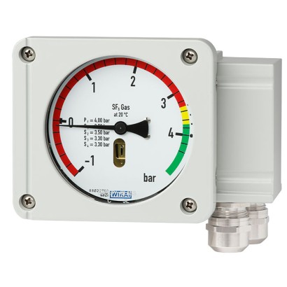
جهاز مراقبة كثافة الغاز الهجين مع حجرة مرجعية
الوصف
كثافة الغاز هي معلمة تشغيل حاسمة بالنسبة لمعدات توزيع الجهد العالي. إذا لم تتوفر كثافة الغاز المطلوبة، فلا يمكن ضمان التشغيل الآمن للمحطة.
توفر أجهزة قياس كثافة الغاز من WIKA تحذيرات موثوقة ضد مستويات الغاز المنخفضة بشكل خطير، حتى في ظل ظروف بيئية قاسية للغاية. إذا انخفضت كثافة الغاز نتيجة لحدوث تسرب، فإن جهات التلامس الخاصة بالمفاتيح ستقوم بالتحويل. وبالإضافة إلى مراقب كثافة الغاز التقليدي، تم إدماج تقنية استشعار عالية الدقة ووحدات إلكترونيات التقييم في الطراز GDM-RC-100-T.
ومن خلال مؤشر الموقع، يمكن قراءة الضغط المستند إلى 20 °C [68 °F] مباشرةً على الجهاز. وبفضل جهات التلامس المدمجة للمفاتيح، يمكن تنفيذ مهام التحويل البسيطة بسرعة وبدون تعقيد. تتيح واجهة Modbus ® المدمجة أو الموصلة، أو تقنية القياس 4 ... 20 mA، إمكانية المراقبة عن بُعد للمحطة.
المزايا
- مناسب تماماً لمشاريع الشبكات الذكية أو التحديث
- Modbus ® يوفر قيم القياس للضغط ودرجة الحرارة وكثافة الغاز كإشارة رقمية
- تُخرج نسخة 4 ... 20 mA الضغط المطلق عند 20 °C [68 °F] أو كثافة الغاز بوحدة g/l كإشارة تناظرية
- مناسب لغاز SF<sub>6</sub> والغازات العازلة البديلة
- عرض محلي كامل لنطاق الكثافة والتفريغ على قرص قياس بقطر 100 مم [3.94 in]
الأسئلة والأجوبة
ما هو نطاق قياس ضغط هذا الجهاز؟
يتوفر الجهاز بنطاقي قياس: 0 … 10 bar و0 … 12.5 bar.
بأي دقة يقيس الجهاز كثافة الغاز؟
لا تتضمن البيانات المتاحة فئة دقة محددة لهذا الطراز.
ما نوع وصلة العملية؟
الوصلة من نوع G1/2 B، والأجزاء الملامسة للوسط مصنوعة من الفولاذ المقاوم للصدأ.
ما الوسط الذي يقيسه الجهاز؟
الجهاز مناسب لغاز SF6 وكذلك للغازات العازلة البديلة.
ما نطاق درجة الحرارة المحيطة للتشغيل؟
يعمل الجهاز ضمن نطاق -40 … +80 °C.
هل الجهاز مقاوم للأتربة والماء؟
نعم، درجة الحماية هي IP67.
هل يحمل الجهاز شهادة لمناطق خطرة؟
لا، البيانات لا تشير إلى أي اعتماد للحماية من الانفجار؛ الشهادة الوحيدة المذكورة هي RoHS.
ما الذي يميز GDM-RC-100-T عن أجهزة مراقبة كثافة الغاز التقليدية؟
يجمع بين المؤشر المحلي الكامل على قرص بقطر 100 mm [3.94 in] وجهاز تحويل مدمج، مع واجهة Modbus ® أو خرج 4 ... 20 mA، ما يجعله مثالياً لمشاريع الشبكة الذكية والتحديث.
| الطراز | GDM-RC-100-T |
| السلسلة | GDM |
| النوع الفرعي | Hybrid gas density monitor with reference chamber |
| نطاق الضغط | 0…10 bar · 0…12.5 bar |
| درجة حرارة الكثافة المرجعية | 20 °C |
| وصلة العملية | G1/2 B |
| إشارة الخرج | Modbus RTU · 4 ... 20 mA |
| نقاط التبديل | 4 |
| مادة الأجزاء الملامسة | Stainless steel |
| حرارة المحيط | −40…+80 °C |
| تصنيف IP | IP67 |
| الشهادات | RoHS |
| تعويض درجة الحرارة | نعم |
| Measurement principle | Reference gas measurement |
|---|---|
| Nominal size of the optical indication | 100 mm[3.94 in] |
| Self-indication in case of malfunction | Integrated into the instrument, the switch contact is actuated in case of leakage in the reference chamber |
| Type of measuring element | Bellows measuring system with reference chamber, piezo pressure sensor with temperature compensation |
|---|
| Switching accuracy Calibration pressure established by means of reference isochore, generated by Prof. Bier | ||
|---|---|---|
| -1 ...+5 bar at 20 °C [-14.50 ... +72.51 psi at 68 °F] | ±70 mbar [±1.01 psi] at calibration pressure at 20 °C [68 °F], gaseous phase ±100 mbar [±1.45 psi] at calibration pressure at -30 ...+50 °C [-22 ...+122 °F], gaseous phase | |
| -1 ...+9 bar at 20 °C [-14.50 ... +130.53 psi at 68 °F] | ±100 mbar [±1.45 psi] at calibration pressure at 20 °C [68 °F], gaseous phase ±150 mbar [±2.17 psi] at calibration pressure at -30 ...+50 °C [-22 ...+122 °F], gaseous phase | |
| -1 ... +11.5 bar at 20 °C [-14.50 ... +166.79 psi at 68 °F] | ±150 mbar [±2.17 psi] at calibration pressure at 20 °C [68 °F], gaseous phase ±200 mbar [±2.90 psi] at calibration pressure at -30 ...+50 °C [-22 ...+122 °F], gaseous phase | |
| Calibration pressure | First switch point below filling pressure | |
| Indication accuracy | ||
| -1 ...+5 bar at 20 °C [-14.50 ... +72.51 psi at 68 °F] | ±70 mbar [±1.01 psi] at calibration pressure at 20 °C [68 °F], gaseous phase ±100 mbar [±1.45 psi] at calibration pressure at -30 ...+50 °C [-22 ...+122 °F], gaseous phase | |
| -1 ...+9 bar at 20 °C [-14.50 ... +130.53 psi at 68 °F] | ±100 mbar [±1.45 psi] at calibration pressure at 20 °C [68 °F], gaseous phase ±150 mbar [±2.17 psi] at calibration pressure at -30 ...+50 °C [-22 ...+122 °F], gaseous phase | |
| -1 ... +11.5 bar at 20 °C [-14.50 ... +166.79 psi at 68 °F] | ±150 mbar [±2.17 psi] at calibration pressure at 20 °C [68 °F], gaseous phase ±200 mbar [±2.90 psi] at calibration pressure at -30 ...+50 °C [-22 ...+122 °F], gaseous phase | |
| Switch hysteresis | Measuring range | Hysteresis level |
| -1 ...+5 bar at 20 °C [-14.50 ... +72.51 psi at 68 °F] | Typically < 90 mbar[< 1.30 psi] 1) | |
| -1 ... +7.5 bar at 20 °C [-14.50 ... +108.77 psi at 68 °F] | Typically < 150 mbar[< 2.17 psi] 1) | |
| -1 ... +11.5 bar at 20 °C [-14.50 ... +166.79 psi at 68 °F] | Typically < 220 mbar[< 3.19 psi] 1) | |
| Lower switch hysteresis on request |
| Measuring range | ■ 0 ... 10 bar abs. at 20 °C [0 ... 145.03 psi abs. at 68 °F] SF₆ gas ■ 0 ... 12.5 bar abs. at 20 °C [0 ... 181.29 psi abs. at 68 °F] SF₆ gas | |
|---|---|---|
| Maximum overpressure | 1.43 times the measuring range | |
| Minimum bursting strength | 30 bar [435.11 psi] | |
| Dial | ||
| Scale range | End of measuring range | 1.3 bar or 1.8 bar [18.85 psi or 26.10 psi] above the first switch point and below the filling pressure |
| Scale graduation | ■ Single scale (divided into sections of different colours) ■ Double scale (divided into sections of different colours) ■ Triple scale (divided into sections of different colours) | |
| Material | Aluminium |
عرض الكل (20)
| Standard | EN 837 |
|---|---|
| Thread size | G1/2 B |
| Connection | Axial or radial |
| Spanner flats | 22 mm[0.86 in] |
| Material | Stainless steel |
| Switch model | Potential-free change-over contact |
|---|---|
| Number of switches | ■ 1 x switch contact ■ 2 x switch contact ■ 3 x switch contact ■ 4 x switch contact Up to four switch contacts possible as change-over contacts |
| Switching function | Change-over contact |
| Switching direction | ■ Falling density ■ Rising density |
| Switch point setting | In accordance with customer specification, max. difference of lowest to highest contact: 4 bar [58.01 psi] |
| Maximum switching cycles | 10,000 mechanical and electrical |
| Insulation resistance of contact | > 100MΩ |
| Min. switching current | 10mA |
| Min. switching voltage | 12V |
| Circuits | Galvanically isolated |
| Monitoring functions | |
| Self-monitoring | Integrated into the instrument, the switch contact is actuated in case of leakage in the reference chamber |
| Auxiliary power [V] | Resistive load [A] | Inductive load [A] |
|---|---|---|
| ≤ DC 30 | 5 1) | 3 1) |
| ≤ DC 50 | 1 | 1 |
| ≤ DC 75 | 0.75 | 0.75 |
| ≤ DC 125 | 0.5 | 0.03 |
| ≤ DC 250 | 0.25 | 0.03 |
| ≤ AC 125 | 5 1) | 2 1) |
| ≤ AC 250 | 5 1) | 2 1) |
| Connection type | 12-pin TTI plug-in terminal |
|---|---|
| Wire cross-section | ■ Min.0.25mm 2 ■ Max.2.5mm 2 |
| Grounding | In cable socket |
| Material (wetted) | |
|---|---|
| Reference chamber (pressure element) | Stainless steel, filled with reference gas |
| Process connection | Stainless steel |
| Material (in contact with the environment) | |
| Case and cover | Aluminium die-casting, powder-coated |
| Cable gland of the switch contacts | → For cable glands, see 'Versions of cable glands for model GDM-RC-100-T with integrated gas density sensor' |
| Movement | Brass |
| Pointer | Aluminium, black |
| Window | Laminated safety glass |
| Dial | Aluminium |
| Place of use | Indoor/Outdoor |
|---|---|
| Altitude | Up to 2,000 m[6,562 ft] above sea level |
| Medium temperature range | -40 ...+80 °C [-40 ...+176 °F], gaseous phase |
| Operating temperature | -40 ...+80 °C [-40 ...+176 °F], gaseous phase |
| Ambient temperature range | -40 ...+80 °C [-40 ...+176 °F], gaseous phase |
| Storage temperature | -40 ...+70 °C [-58 ...+158 °F] |
| Humidity | ≤ 95 %relative humidity |
| Condensation | Non-condensing Compensating diaphragm against condensation |
| Helium leak test | ≤ 1 x 10 -8 mbar x l/s |
| Vibration resistance | 4g at 50 mbar [0.72 psi] distance from the switch point, no contact bounce (20 ...80 Hz) |
| Shock resistance | ■ 50g / 11 ms, no contact bounce with 200 mbar [2.90 psi] distance from the switch point ■ 150g without damage |
| Ingress protection of the complete instrument | ■ IP65, IP67 for versions with integrated gas density sensor ■ IP67 for versions with attached gas density sensor |
| Permissible pollution degree | 2 (per EN 61010-1) |
| Weight in kg | On request (depending on configuration) |
| Product label | Lasered onto the reference chamber, highest weather resistance |
|---|
| Electric strength | ■ 2 kV pin on grounding (case) ■ 2 kV pin on pin (switch contact to switch contact) ■ 1 kV pin on pin within the switch contact - 1 minute |
|---|
| Compensated pressure range in bar abs. at 20 °C [psi abs. at 68 °F] (g/l SF₆) | Pressure in bar abs. [psi abs.] | Temperature | Output parameters | Output signal |
|---|---|---|---|---|
| 0 …2(12.28) [0 ... 29.00] | 0 …2.4 [0 ... 34.80] | -40 …+80 °C [-40 ...+176 °F] | ■ Density ■ Pressure at 20 °C [68 °F] ■ Pressure ■ Temperature | Modbus ® RTU |
| 0 …3(18.65) [0 ... 43.51] | 0 …3.7 [0 ... 53.66] | |||
| 0 ... 6 (38.87) [0 ... 87.02] | 0 ... 7.5 [0 ... 108.77] | |||
| 0 …8(53.4) [0 ... 116.03] | 0 …10.1 [0 ... 146.48] | |||
| 0 …10(68.96) [0 ... 145.03] | 0 …12.9 [0 ... 187.09] | |||
| 0 …12(85.79) [0 ... 174.04] | 0 …15.7 [0 ... 227.70] | |||
| 0 …16(124.64) [0 ... 232.06] | 0 …21.3 [0 ... 308.93] |
| Accuracy 1) | ||
|---|---|---|
| Compensated pressure ranges in bar abs. at 20 °C [psi abs. at 68 °F] (g/l SF₆) 0 …2(12.28) [0 ... 29.00] 0 …3(18.65) [0 ... 43.51] 0 ... 6 (38.87) [0 ... 87.02] | For -40 ... -20 °C [-40 ... -4 °F] For -20 ...+80 °C [-4 ...+176 °F] | ■ ±2% ■ ±1.5% ■ ±1.25% ■ ±0.75% |
| Compensated pressure ranges in bar abs. at 20 °C [psi abs. at 68 °F] (g/l SF₆) 0 …8(53.4) [0 ... 116.03] 0 …10(68.96) [0 ... 145.03] 0 …12(85.79) [0 ... 174.04] 0 …16(124.64) [0 ... 232.06] | For -40 ...+80 °C [-40 ...+176 °F] | ■ ±1.25% ■ ±0.6% |
|---|---|---|
| Pressure accuracy | ■ ±1 %at 20 °C [68 °F] ■ ±0.2 %at 20 °C [68 °F] | |
| Temperature accuracy | ±1.5 K | |
| Reference conditions | Per IEC 61298-1 |
| Compensated pressure range in bar abs. at 20 °C [psi abs. at 68 °F] (g/l SF₆) | Accuracy 1) | Output parameters | Output signal |
|---|---|---|---|
| 0 …2(12.28) [0 ... 29.00] | ■ ±2% ■ ±1.5% | Absolute pressure at 20 °C [68 °F] | 4 ...20mA |
| 0 …3(18.65) [0 ... 43.51] | |||
| 0 ... 6 (38.87) [0 ... 87.02] | |||
| 0 …8(53.4) [0 ... 116.03] | |||
| 0 …10(68.96) [0 ... 145.03] | |||
| 0 …12(85.79) [0 ... 174.04] | |||
| 0 …16(124.64) [0 ... 232.06] |
| Density range in g/l SF 6 (compensated pressure range in bar abs. at 20 °C [psi abs. at 68 °F]) | Accuracy 1) | Output parameters | Output signal |
|---|---|---|---|
| 0 …10(1.64) [0 ... 145.03] | ■ ±2% ■ ±1.5% | SF₆ gas density in g/l | 4 ...20mA |
| 0 …16(2.59) [0 ... 232.06] | |||
| 0 ... 25 (3.97) [0 ... 362.59] | |||
| 0 …40(6.16) [0 ... 580.15] | |||
| 0 …60(8.87) [0 ... 870.22] | |||
| 0 …80(11.33) [0 ... 1,160.3] |
| Compensated pressure range in bar abs. at 20 °C [psi abs. at 68 °F] (g/l SF₆) | Overload safety in bar abs. [psi abs.] | Burst pressure in bar abs. [psi abs.] |
|---|---|---|
| 0 ... 2 (12.28) [0 ... 29.00] | 6.2 [89.92] | 10 [145.03] |
| 0 ... 3 (18.65) [0 ... 43.51] | 14.5 [210.30] | 24 [348.09] |
| 0 ... 6 (38.87) [0 ... 87.02] | 14.5 [210.30] | 24 [348.09] |
| 0 ... 8 (53.4) [0 ... 116.03] | 31 [449.61] | 52 [754.19] |
| 0 ... 10 (68.96) [0 ... 145.03] | 31 [449.61] | 52 [754.19] |
| 0 ... 12 (85.79) [0 ... 174.04] | 31 [449.61] | 52 [754.19] |
| 0 ... 16 (124.64) [0 ... 232.06] | 62 [899.23] | 103 [1,493.89] |
| Case material | 316L |
|---|---|
| Case options | ■ Cable outlet ■ Metal cable outlet, shield optionally connected (heavy-duty version) |
| Name in accordance with IUPAC 2) nomenclature | Abbreviation | Description (CAS no.) |
|---|---|---|
| Sulphur hexafluoride | SF 6 | 2551-62-4 |
| Nitrogen | N 2 | 7727-37-9 |
| Tetrafluoromethane | CF 4 | 75-73-0 |
| Oxygen 3) | O 2 | 7782-44-7 |
| Carbon dioxide | CO 2 | 124-38-9 |
| 2,3,3,3-Tetrafluoro-2-(trifluoromethyl)propanenitrile 4) | C4-FN (fluoronitrile) | 42532-60-5 |
| Helium | He | 7440-59-7 |
| Argon | Ar | 7440-37-1 |
لم تجد الإجابة في الوثائق؟ سيرد المهندس خلال يوم عمل.
اسأل المهندس →