
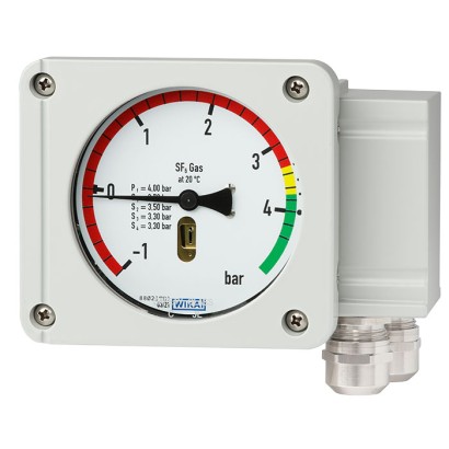
Гібридний монітор густини газу з камерою порівняння
Опис
Густина газу є критично важливим параметром робочого режиму для високовольтного комутаційного обладнання. Якщо необхідна густина газу відсутня, неможливо гарантувати безпечну роботу установки.
Вимірювальні прилади WIKA для густини газу забезпечують надійні попередження про небезпечно низькі рівні газу навіть за екстремальних умов навколишнього середовища. Якщо густина газу знижується внаслідок витоку, перемикаються контакти вимикача. Окрім традиційного монітора густини газу, у моделі GDM-RC-100-T вбудовано високоточну технологію сенсорного вимірювання та електроніку обробки.
Завдяки індикації на місці тиск, розрахований для 20 °C [68 °F], можна зчитати безпосередньо на приладі. Із вбудованими контактами перемикання прості задачі комутації можна реалізувати швидко та без ускладнень. Вбудований або приєднаний інтерфейс Modbus ® чи вимірювальна технологія 4 ... 20 mA дають змогу здійснювати дистанційний моніторинг установки.
Особливості
- Ідеально підходить для проєктів smart grid або модернізації
- Modbus ® передає виміряні значення тиску, температури та густини газу як цифровий сигнал
- Версія з виходом 4 ... 20 mA видає як аналоговий сигнал абсолютний тиск при 20 °C [68 °F] або щільність газу в г/л
- Придатний для SF<sub>6</sub> та альтернативних ізоляційних газів
- Повна індикація на місці діапазону щільності та вакууму на шкалі 100 мм [3.94 in]
Питання та відповіді
Які вихідні сигнали підтримує GDM-RC-100-T?
Інтерфейс Modbus RTU, що передає цифрові значення тиску, температури та густини газу, або аналоговий сигнал 4 ... 20 mA (абсолютний тиск при 20 °C або густина в г/л).
Для яких газів придатний цей монітор?
Для SF6 та альтернативних ізоляційних газів.
Який діапазон температур навколишнього середовища допускається?
Від -40 °C до +80 °C.
Яке процесне з'єднання має прилад?
G1/2 B.
Який ступінь захисту корпусу?
IP67.
Скільки комутаційних контактів доступно для сигналізації?
Чотири — для реалізації простих задач комутації, наприклад тривоги при зниженні густини газу через витік.
Як зчитуються показання на місці експлуатації?
Тиск, розрахований для 20 °C [68 °F], можна зчитати безпосередньо на циферблаті діаметром 100 мм [3,94 in], який охоплює діапазон густини та вакууму.
Чим GDM-RC-100-T відрізняється від звичайного монітора густини газу?
Окрім традиційної індикації, у нього вбудовано високоточну технологію сенсорного вимірювання та електроніку обробки, а також камера порівняння, що дає змогу дистанційний моніторинг через Modbus® чи 4 ... 20 mA.
| Модель | GDM-RC-100-T |
| Сімейство | GDM |
| Підтип | Hybrid gas density monitor with reference chamber |
| Діапазон тиску | 0…10 bar · 0…12.5 bar |
| Опорна температура густини | 20 °C |
| Технологічне приєднання | G1/2 B |
| Вихідний сигнал | Modbus RTU · 4 ... 20 mA |
| Перемикальні контакти | 4 |
| Матеріал змочуваних частин | Stainless steel |
| Темп. навколишнього середовища | −40…+80 °C |
| Ступінь захисту IP | IP67 |
| Сертифікати | RoHS |
| Температурна компенсація | Так |
| Measurement principle | Reference gas measurement |
|---|---|
| Nominal size of the optical indication | 100 mm[3.94 in] |
| Self-indication in case of malfunction | Integrated into the instrument, the switch contact is actuated in case of leakage in the reference chamber |
| Type of measuring element | Bellows measuring system with reference chamber, piezo pressure sensor with temperature compensation |
|---|
| Switching accuracy Calibration pressure established by means of reference isochore, generated by Prof. Bier | ||
|---|---|---|
| -1 ...+5 bar at 20 °C [-14.50 ... +72.51 psi at 68 °F] | ±70 mbar [±1.01 psi] at calibration pressure at 20 °C [68 °F], gaseous phase ±100 mbar [±1.45 psi] at calibration pressure at -30 ...+50 °C [-22 ...+122 °F], gaseous phase | |
| -1 ...+9 bar at 20 °C [-14.50 ... +130.53 psi at 68 °F] | ±100 mbar [±1.45 psi] at calibration pressure at 20 °C [68 °F], gaseous phase ±150 mbar [±2.17 psi] at calibration pressure at -30 ...+50 °C [-22 ...+122 °F], gaseous phase | |
| -1 ... +11.5 bar at 20 °C [-14.50 ... +166.79 psi at 68 °F] | ±150 mbar [±2.17 psi] at calibration pressure at 20 °C [68 °F], gaseous phase ±200 mbar [±2.90 psi] at calibration pressure at -30 ...+50 °C [-22 ...+122 °F], gaseous phase | |
| Calibration pressure | First switch point below filling pressure | |
| Indication accuracy | ||
| -1 ...+5 bar at 20 °C [-14.50 ... +72.51 psi at 68 °F] | ±70 mbar [±1.01 psi] at calibration pressure at 20 °C [68 °F], gaseous phase ±100 mbar [±1.45 psi] at calibration pressure at -30 ...+50 °C [-22 ...+122 °F], gaseous phase | |
| -1 ...+9 bar at 20 °C [-14.50 ... +130.53 psi at 68 °F] | ±100 mbar [±1.45 psi] at calibration pressure at 20 °C [68 °F], gaseous phase ±150 mbar [±2.17 psi] at calibration pressure at -30 ...+50 °C [-22 ...+122 °F], gaseous phase | |
| -1 ... +11.5 bar at 20 °C [-14.50 ... +166.79 psi at 68 °F] | ±150 mbar [±2.17 psi] at calibration pressure at 20 °C [68 °F], gaseous phase ±200 mbar [±2.90 psi] at calibration pressure at -30 ...+50 °C [-22 ...+122 °F], gaseous phase | |
| Switch hysteresis | Measuring range | Hysteresis level |
| -1 ...+5 bar at 20 °C [-14.50 ... +72.51 psi at 68 °F] | Typically < 90 mbar[< 1.30 psi] 1) | |
| -1 ... +7.5 bar at 20 °C [-14.50 ... +108.77 psi at 68 °F] | Typically < 150 mbar[< 2.17 psi] 1) | |
| -1 ... +11.5 bar at 20 °C [-14.50 ... +166.79 psi at 68 °F] | Typically < 220 mbar[< 3.19 psi] 1) | |
| Lower switch hysteresis on request |
| Measuring range | ■ 0 ... 10 bar abs. at 20 °C [0 ... 145.03 psi abs. at 68 °F] SF₆ gas ■ 0 ... 12.5 bar abs. at 20 °C [0 ... 181.29 psi abs. at 68 °F] SF₆ gas | |
|---|---|---|
| Maximum overpressure | 1.43 times the measuring range | |
| Minimum bursting strength | 30 bar [435.11 psi] | |
| Dial | ||
| Scale range | End of measuring range | 1.3 bar or 1.8 bar [18.85 psi or 26.10 psi] above the first switch point and below the filling pressure |
| Scale graduation | ■ Single scale (divided into sections of different colours) ■ Double scale (divided into sections of different colours) ■ Triple scale (divided into sections of different colours) | |
| Material | Aluminium |
Переглянути всі (20)
| Standard | EN 837 |
|---|---|
| Thread size | G1/2 B |
| Connection | Axial or radial |
| Spanner flats | 22 mm[0.86 in] |
| Material | Stainless steel |
| Switch model | Potential-free change-over contact |
|---|---|
| Number of switches | ■ 1 x switch contact ■ 2 x switch contact ■ 3 x switch contact ■ 4 x switch contact Up to four switch contacts possible as change-over contacts |
| Switching function | Change-over contact |
| Switching direction | ■ Falling density ■ Rising density |
| Switch point setting | In accordance with customer specification, max. difference of lowest to highest contact: 4 bar [58.01 psi] |
| Maximum switching cycles | 10,000 mechanical and electrical |
| Insulation resistance of contact | > 100MΩ |
| Min. switching current | 10mA |
| Min. switching voltage | 12V |
| Circuits | Galvanically isolated |
| Monitoring functions | |
| Self-monitoring | Integrated into the instrument, the switch contact is actuated in case of leakage in the reference chamber |
| Auxiliary power [V] | Resistive load [A] | Inductive load [A] |
|---|---|---|
| ≤ DC 30 | 5 1) | 3 1) |
| ≤ DC 50 | 1 | 1 |
| ≤ DC 75 | 0.75 | 0.75 |
| ≤ DC 125 | 0.5 | 0.03 |
| ≤ DC 250 | 0.25 | 0.03 |
| ≤ AC 125 | 5 1) | 2 1) |
| ≤ AC 250 | 5 1) | 2 1) |
| Connection type | 12-pin TTI plug-in terminal |
|---|---|
| Wire cross-section | ■ Min.0.25mm 2 ■ Max.2.5mm 2 |
| Grounding | In cable socket |
| Material (wetted) | |
|---|---|
| Reference chamber (pressure element) | Stainless steel, filled with reference gas |
| Process connection | Stainless steel |
| Material (in contact with the environment) | |
| Case and cover | Aluminium die-casting, powder-coated |
| Cable gland of the switch contacts | → For cable glands, see 'Versions of cable glands for model GDM-RC-100-T with integrated gas density sensor' |
| Movement | Brass |
| Pointer | Aluminium, black |
| Window | Laminated safety glass |
| Dial | Aluminium |
| Place of use | Indoor/Outdoor |
|---|---|
| Altitude | Up to 2,000 m[6,562 ft] above sea level |
| Medium temperature range | -40 ...+80 °C [-40 ...+176 °F], gaseous phase |
| Operating temperature | -40 ...+80 °C [-40 ...+176 °F], gaseous phase |
| Ambient temperature range | -40 ...+80 °C [-40 ...+176 °F], gaseous phase |
| Storage temperature | -40 ...+70 °C [-58 ...+158 °F] |
| Humidity | ≤ 95 %relative humidity |
| Condensation | Non-condensing Compensating diaphragm against condensation |
| Helium leak test | ≤ 1 x 10 -8 mbar x l/s |
| Vibration resistance | 4g at 50 mbar [0.72 psi] distance from the switch point, no contact bounce (20 ...80 Hz) |
| Shock resistance | ■ 50g / 11 ms, no contact bounce with 200 mbar [2.90 psi] distance from the switch point ■ 150g without damage |
| Ingress protection of the complete instrument | ■ IP65, IP67 for versions with integrated gas density sensor ■ IP67 for versions with attached gas density sensor |
| Permissible pollution degree | 2 (per EN 61010-1) |
| Weight in kg | On request (depending on configuration) |
| Product label | Lasered onto the reference chamber, highest weather resistance |
|---|
| Electric strength | ■ 2 kV pin on grounding (case) ■ 2 kV pin on pin (switch contact to switch contact) ■ 1 kV pin on pin within the switch contact - 1 minute |
|---|
| Compensated pressure range in bar abs. at 20 °C [psi abs. at 68 °F] (g/l SF₆) | Pressure in bar abs. [psi abs.] | Temperature | Output parameters | Output signal |
|---|---|---|---|---|
| 0 …2(12.28) [0 ... 29.00] | 0 …2.4 [0 ... 34.80] | -40 …+80 °C [-40 ...+176 °F] | ■ Density ■ Pressure at 20 °C [68 °F] ■ Pressure ■ Temperature | Modbus ® RTU |
| 0 …3(18.65) [0 ... 43.51] | 0 …3.7 [0 ... 53.66] | |||
| 0 ... 6 (38.87) [0 ... 87.02] | 0 ... 7.5 [0 ... 108.77] | |||
| 0 …8(53.4) [0 ... 116.03] | 0 …10.1 [0 ... 146.48] | |||
| 0 …10(68.96) [0 ... 145.03] | 0 …12.9 [0 ... 187.09] | |||
| 0 …12(85.79) [0 ... 174.04] | 0 …15.7 [0 ... 227.70] | |||
| 0 …16(124.64) [0 ... 232.06] | 0 …21.3 [0 ... 308.93] |
| Accuracy 1) | ||
|---|---|---|
| Compensated pressure ranges in bar abs. at 20 °C [psi abs. at 68 °F] (g/l SF₆) 0 …2(12.28) [0 ... 29.00] 0 …3(18.65) [0 ... 43.51] 0 ... 6 (38.87) [0 ... 87.02] | For -40 ... -20 °C [-40 ... -4 °F] For -20 ...+80 °C [-4 ...+176 °F] | ■ ±2% ■ ±1.5% ■ ±1.25% ■ ±0.75% |
| Compensated pressure ranges in bar abs. at 20 °C [psi abs. at 68 °F] (g/l SF₆) 0 …8(53.4) [0 ... 116.03] 0 …10(68.96) [0 ... 145.03] 0 …12(85.79) [0 ... 174.04] 0 …16(124.64) [0 ... 232.06] | For -40 ...+80 °C [-40 ...+176 °F] | ■ ±1.25% ■ ±0.6% |
|---|---|---|
| Pressure accuracy | ■ ±1 %at 20 °C [68 °F] ■ ±0.2 %at 20 °C [68 °F] | |
| Temperature accuracy | ±1.5 K | |
| Reference conditions | Per IEC 61298-1 |
| Compensated pressure range in bar abs. at 20 °C [psi abs. at 68 °F] (g/l SF₆) | Accuracy 1) | Output parameters | Output signal |
|---|---|---|---|
| 0 …2(12.28) [0 ... 29.00] | ■ ±2% ■ ±1.5% | Absolute pressure at 20 °C [68 °F] | 4 ...20mA |
| 0 …3(18.65) [0 ... 43.51] | |||
| 0 ... 6 (38.87) [0 ... 87.02] | |||
| 0 …8(53.4) [0 ... 116.03] | |||
| 0 …10(68.96) [0 ... 145.03] | |||
| 0 …12(85.79) [0 ... 174.04] | |||
| 0 …16(124.64) [0 ... 232.06] |
| Density range in g/l SF 6 (compensated pressure range in bar abs. at 20 °C [psi abs. at 68 °F]) | Accuracy 1) | Output parameters | Output signal |
|---|---|---|---|
| 0 …10(1.64) [0 ... 145.03] | ■ ±2% ■ ±1.5% | SF₆ gas density in g/l | 4 ...20mA |
| 0 …16(2.59) [0 ... 232.06] | |||
| 0 ... 25 (3.97) [0 ... 362.59] | |||
| 0 …40(6.16) [0 ... 580.15] | |||
| 0 …60(8.87) [0 ... 870.22] | |||
| 0 …80(11.33) [0 ... 1,160.3] |
| Compensated pressure range in bar abs. at 20 °C [psi abs. at 68 °F] (g/l SF₆) | Overload safety in bar abs. [psi abs.] | Burst pressure in bar abs. [psi abs.] |
|---|---|---|
| 0 ... 2 (12.28) [0 ... 29.00] | 6.2 [89.92] | 10 [145.03] |
| 0 ... 3 (18.65) [0 ... 43.51] | 14.5 [210.30] | 24 [348.09] |
| 0 ... 6 (38.87) [0 ... 87.02] | 14.5 [210.30] | 24 [348.09] |
| 0 ... 8 (53.4) [0 ... 116.03] | 31 [449.61] | 52 [754.19] |
| 0 ... 10 (68.96) [0 ... 145.03] | 31 [449.61] | 52 [754.19] |
| 0 ... 12 (85.79) [0 ... 174.04] | 31 [449.61] | 52 [754.19] |
| 0 ... 16 (124.64) [0 ... 232.06] | 62 [899.23] | 103 [1,493.89] |
| Case material | 316L |
|---|---|
| Case options | ■ Cable outlet ■ Metal cable outlet, shield optionally connected (heavy-duty version) |
| Name in accordance with IUPAC 2) nomenclature | Abbreviation | Description (CAS no.) |
|---|---|---|
| Sulphur hexafluoride | SF 6 | 2551-62-4 |
| Nitrogen | N 2 | 7727-37-9 |
| Tetrafluoromethane | CF 4 | 75-73-0 |
| Oxygen 3) | O 2 | 7782-44-7 |
| Carbon dioxide | CO 2 | 124-38-9 |
| 2,3,3,3-Tetrafluoro-2-(trifluoromethyl)propanenitrile 4) | C4-FN (fluoronitrile) | 42532-60-5 |
| Helium | He | 7440-59-7 |
| Argon | Ar | 7440-37-1 |
Не знайшли відповіді у документації? Інженер відповість впродовж робочого дня.
Запитати інженера →