
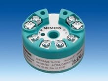
The smart solution - The transmitter with the same capabilities as a SITRANS TH200 and a standardized HART interface.
This universal transmitter integrates your temperature measurement in the TIA concept (Totally Integrated Automation). This makes central engineering possible, bringing you time and cost benefits.
SIMATIC PDM or another HART programming tool can be used for the configuration.
Особенности
- Two-wire transmitter
- Assembly in connection head type B (DIN 43729) or larger, or on a standard DIN rail
- Communication-capable (HART protocol rev. 5.9 for SITRANS TH300, proprietary protocol for SITRANS TH200); this enables programming of sensor connection, measuring range, etc.
- Electrically isolated
- Intrinsically-safe version for use in potentially explosive areas
- Two additional test pins for connection of a multimeter support the measurement of the current signal without interrupting the current loop
- Operational status indication (LED green or red)
- Special characteristic
- Diagnostic functions with SITRANS TH300 (slave pointer, operating hours counter, simulation)
Область применения
The SITRANS TH200 and SITRANS TH300 transmitters can be used in all industries. Due to their compact size they can be installed in the connection head type B (DIN 43729) or larger. The following sensors/signal sources can be connected over their universal input module:
- Resistance thermometer
- Thermocouple elements
- Resistance-based sensors/potentiometers
- DC voltage sources
The output signal is a direct current from 4 to 20 mA in accordance with the sensor characteristic.
Transmitters of the "Intrinsically-safe" type of protection can be installed within potentially explosive atmospheres (zone 0). The declarations of conformity comply with the IEC standard.
Функции
Mode of operation
The signal output by a resistance-based sensor (two-wire, three-wire or four-wire system) or thermocouple is converted into a digital signal by an analog-to-digital converter. This is then evaluated in a microcontroller (μC1), corrected in accordance with the sensor characteristic and transmitted to the microcontroller (μC2) over the electrical isolation. There, the analog output value is calculated, the function status is determined over LED, and the communication data are preprocessed Over a digital/analog converter, the measured value is then converted to an output current of 4 to 20 mA. The power supply is located in the output signal circuit.
The SITRANS TH200 and SITRANS TH300 are parameterized and operated using a PC, which is connected to the two-wire system over a suitable interface module (SIPROM T modem or HART modem). A hand-held communicator can also be used to parameterize the SITRANS TH300. The signals required for communication according to the HART protocol rev. 5.9 are superimposed on the current signal in accordance with the FSK method (Frequency Shift Keying). The data specific to the transmitter and the data for parameterization are stored in two non-volatile memories (EEPROM).
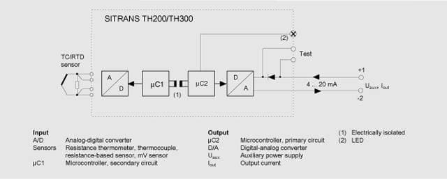 Function diagram for SITRANS TH200 and SITRANS TH300
Технические данные
| Input | |
|---|---|
| Resistance thermometer | |
| Measured variable | Temperature |
| Sensor type | |
| - to IEC 60751 | Pt25 to Pt1000 |
| - to JIS C 1604; a=0.00392 K-1 | Pt25 to Pt1000 |
| - to IEC 60751 | Ni25 to Ni1000 |
| - Special type | over special characteristic (max. 30 points) |
| Sensor factor | 0.25 ... 10 (adaptation of the basic type, e.g. Pt100 to version Pt25 ... Pt1000) |
| Units | °C or °F |
| Connection | |
| - Standard connection | 1 resistance thermometer (RTD) in 2-wire, 3-wire or 4-wire system |
| - Generation of average value | 2 identical resistance thermometers in 2-wire system for generation of average temperature |
| - Generation of difference | 2 identical resistance thermometers (RTD) in 2-wire system (RTD 1 – RTD 2 or RTD 2 – RTD 1) |
| Interface | |
| - Two-wire system | Parameterizable line resistance ≤ 100 Ω (loop resistance) |
| - Three-wire system | No balancing required |
| - Four-wire system | No balancing required |
| Sensor current | ≤ 0.45 mA |
| Response time | ≤ 250 ms for 1 sensor with open-circuit monitoring |
| Open-circuit monitoring | can be switched off |
| Short-circuit monitoring | can be switched off (value is adjustable) |
| Range | Parameterizable (see table "Digital measuring errors") |
| Min. measured span | 10 °C (18 °F) |
| Characteristic | Temperature-linear or special characteristic |
| Resistance-based sensors | |
| Measured variable | Actual resistance |
| Sensor type | Resistance-based, potentiometers |
| Units | Ω |
| Connection | |
| - Normal connection | 1 resistance-based sensor (R) in 2-wire, 3-wire or 4-wire system |
| - Generation of average value | 2 resistance-based sensors in 2-wire system for generation of average value |
| - Generation of difference | 2 resistance thermometers in 2-wire system (R1 – R2 or R2 – R1) |
| Interface | |
| - Two-wire system | Parameterizable line resistance ≤ 100 Ω (loop resistance) |
| - Three-wire system | No balancing required |
| - Four-wire system | No balancing required |
| Sensor current | ≤ 0.45 mA |
| Response time | ≤ 250 ms for 1 sensor with open-circuit monitoring |
| Open-circuit monitoring | can be switched off |
| Short-circuit monitoring | can be switched off (value is adjustable) |
| Range | Parameterizable, max. 0 ... 2200 Ω (see Table "Digital measuring errors") |
| Min. measured span | 5 Ω ... 25 Ω (see Table "Digital measuring errors") |
| Characteristic | Resistance-linear or special characteristic |
| Thermocouple elements | |
| Measured variable | Temperature |
| Sensor type (thermocouples) | |
| - Type B | Pt30Rh-Pt6Rh to DIN IEC 584 |
| - Type C | W5%-Re to ASTM 988 |
| - Type D | W3%-Re to ASTM 988 |
| - Type E | NiCr-CuNi to DIN IEC 584 |
| - Type J | Fe-CuNi to DIN IEC 584 |
| - Type K | NiCr-Ni to DIN IEC 584 |
| - Type L | Fe-CuNi to DIN 43710 |
| - Type N | NiCrSi-NiSi to DIN IEC 584 |
| - Type R | Pt13Rh-Pt to DIN IEC 584 |
| - Type S | Pt10Rh-Pt to DIN IEC 584 |
| - Type T | Cu-CuNi to DIN IEC 584 |
| - Type U | Cu-CuNi to DIN 43710 |
| Units | °C or °F |
| Connection | |
| - Standard connection | 1 thermocouple (TC) |
| - Generation of average value | 2 thermocouples (TC) |
| - Generation of difference | 2 thermocouples (TC) TC1 – TC2 or TC2 – TC1 |
| Response time | ≤ 250 ms for 1 sensor with open-circuit monitoring |
| Open-circuit monitoring | can be switched off |
| Cold junction compensation | |
| - Internal | With integrated Pt100 resistance thermometer |
| - External | With external Pt100 IEC 60571 (2-wire or 3-wire connection) |
| - External fixed | Cold junction temperature can be set as fixed value |
| Range | Parameterizable (see table "Digital measuring errors") |
| Min. measured span | Min. 50 ... 199 °C (90 ... 180 °F) (see table "Digital measuring errors") |
| Characteristic | Temperature-linear or special characteristic |
| mV Sensor | |
| Measured variable | DC voltage |
| Sensor type | DC voltage source (DC voltage source possible over an externally connected resistor) |
| Units | mV |
| Response time | ≤ 250 ms for 1 sensor with open-circuit monitoring |
| Open-circuit monitoring | can be switched off |
| Short-circuit monitoring | can be switched off (value is adjustable) |
| Range | -10 ... 70 mV-100 1100 mV |
| Min. measured span | 2 mV or 20 mV |
| Overload capacity of the input | -1.5 ... +3.5 V DC |
| Input resistance | ≥ 1 MΩ |
| Characteristic | Voltage-linear or special characteristic |
| Output | |
| Output signal | 4 ... 20 mA, 2-wire With SITRANS TH300, additional communication acc. to HART Rev. 5.9 |
| Power supply | 11 ... 35 V DC (to 30 V with EEx) |
| Max. load | (Uaux – 11 V)/0.023 A |
| Overrange | 3.6 ... 23 mA, continuously adjustable (default range: 3.84 mA ... 20.50 mA) |
| Error signal (e.g. in the event of sensor breakage) | 3.6 ... 23 mA, continuously adjustable (default value: 22.8 mA) |
| Sample cycle | 0.25 s nominal |
| Damping | Software filter 1st order 0 ... 30 s (parameterizable) |
| Protection | Against reversed polarity |
| Electrically isolated | Input against output (1 kVeff) |
| Measuring accuracy | |
| Digital measuring errors | See Table "Digital measuring errors" |
| Reference conditions | |
| - Power supply | 24 V ± 1% |
| - Load | 500 Ω |
| - Storage temperature | 23 °C |
| - Warming-up time | > 5 min |
| Error in the analog ouput (digital/analog converter) | < 0.1 % of span |
| Error due to internal cold junction | < 0.5 °C (0.9 °F) |
| Temperature effect | < 0.1% der max. span/10°C (18 °F) |
| Power supply effect | < 0.005% of span/V |
| Effect of load impedance | < 0.012% of span/100 Ω |
| Long-term drift | |
| - in the first month | < 0.02% of max. span |
| - after one year | < 0.03% of max. span |
| - after 5 years | < 0.04% of max. span |
| Rated conditions | |
| Ambient temperature | |
| Storage temperature | -40 ... +85 °C (-40 ... 185 °F) |
| Functional temperature | -40 ... +85 °C (-40 ... 185 °F) |
| Relative humidity | < 98%, with condensation |
| Electromagnetic compatibility | acc. to DIN EN 61326 and NE21 |
| Construction | |
| Material | Molded plastic |
| Approx. weight | 50 g (0.11 lb) |
| Dimensions | See "Dimension drawings" |
| Cross-section of cables | Max. 2.5 mm² (AWG 13) |
| Degree of protection to EN 60529 | |
| - Enclosure | IP40 |
| - Terminals | IP00 |
| Certificate and approvals | |
| Explosion protection ATEX | |
| - "Intrinsically-safe" type of protection | II 1G EEx ia IIC T6/T4II 2(1)G EEx ia/ib IIC T6/T4 |
| - "Operating equipment that is non-ignitable and has limited energy" type of protection | II 3G EEx nAL IIC T6/T4 |
| - EC type test certificate | PTB 05 ATEX 2040X |
| Explosion protection to FM for USA and Canada (cFMUS) | |
| - FM approval | PID 3024169 |
| - Degree of protection | IS Cl I, II, III, Div 1, GP ABCDEFG T4/T5/T6IS Cl I, ZN 0, 1 AEx ia IIC T4/T5/T6NI Cl I, II, III, Div 2, GP ABCDFG T4/T5/T6Cl I, ZN2, GP IIC T4/T5/T6 |
| Software requirements for SIPROM T | |
| PC operating system: | Windows ME, 2000 and XP; also Windows 95, 98 and 98 SE, but only in connection with RS 232 modem. |
Factory setting:
- Pt100 (IEC 751) with three-wire circuit
- Measuring range: 0 ... 100 °C (32 ... 212 °F)
- Fault current: 22.8 mA
- Sensor offset: 0 °C (0 °F)
- Damping 0.0 s
Digital measuring errors
Resistance thermometer
| input | Range | Min. measured span | Digital accuracy | ||
|---|---|---|---|---|---|
| °C (°F) | °C | (°F) | °C | (°F) | |
| To IEC 60751 | |||||
| Pt25 | -200 ... +850 (-328 ... +1562) | 10 | (18) | 0.2 | (0.36) |
| Pt50 | -200 ... +850 (-328 ... +1562) | 10 | (18) | 0.15 | (0.27) |
| Pt100 ... Pt200 | -200 ... +850 (-328 ... +1562) | 10 | (18) | 0.1 | (0.18) |
| Pt500 | -200 ... +850 (-328 ... +1562) | 10 | (18) | 0.15 | (0.27) |
| Pt1000 | -200 ... +350 (-328 ... +662) | 10 | (18) | 0.15 | (0.27) |
| to JIS C1604-81 | |||||
| Pt25 | -200 ... +649 (-328 ... +1200) | 10 | (18) | 0.2 | (0.36) |
| Pt50 | -200 ... +649 (-328 ... +1200) | 10 | (18) | 0.15 | (0.27) |
| Pt100 ... Pt200 | -200 ... +649 (-328 ... +1200) | 10 | (18) | 0.1 | (0.18) |
| Pt500 | -200 ... +649 (-328 ... +1200) | 10 | (18) | 0.15 | (0.27) |
| Pt1000 | -200 ... +350 (-328 ... +662) | 10 | (18) | 0.15 | (0.27) |
| Ni 25 to Ni1000 | -60 ... +250 (-76 ... +482) | 10 | (18) | 0.1 | (0.18) |
Resistance-based sensors
| Input | Range | Min. measured span | Digital accuracy |
|---|---|---|---|
| Ω | Ω | Ω | |
| Resistance | 0 ... 390 | 5 | 0.05 |
| Resistance | 0 ... 2200 | 25 | 0.25 |
Thermocouple elements
| input | Range | Min. measured span | Digital accuracy | |||
|---|---|---|---|---|---|---|
| °C | (°F) | °C | (°F) | °C | (°F) | |
| Type B | 0 ... +1820 | (32 ... 3308) | 100 | (180) | 2 | (5.4) |
| Type C (W5) | 0 ... 2300 | (32 ... 4172) | 100 | (180) | 2 | (3.6) |
| Type D (W3) | 0 ... 2300 | (32 ... 4172) | 100 | (180) | 2 | (3.6) |
| Type E | -200 ... +1000 | (-328 ... +1832) | 50 | (90) | 1 | (1.8) |
| Type J | -210 ... +1200 | (-346 ... +2192) | 50 | (90) | 1 | (1.8) |
| Type K | -230 ... +1370 | (-382 ... +2498) | 50 | (90) | 1 | (1.8) |
| Type L | -200 ... +900 | (-328 ... +1652) | 50 | (90) | 1 | (1.8) |
| Type N | -200 ... +1300 | (-328 ... +2372) | 50 | (90) | 1 | (1.8) |
| Type R | -50 ... +1760 | (-58 ... +3200) | 100 | (180) | 2 | (3.6) |
| Type S | -50 ... +1760 | (-58 ... +3200) | 100 | (180) | 2 | (3.6) |
| Type T | -200 ... +400 | (-328 ... +752) | 40 | (72) | 1 | (1.8) |
| Type U | -200 ... +600 | (-328 ... +1112) | 50 | (90) | 2 | (3.6) |
mV Sensor
| input | Range | Min. measured span | Digital accuracy |
|---|---|---|---|
| mV | mV | μV | |
| mV Sensor | -10 ... +70 | 2 | 40 |
| mV Sensor | -100 ... +1100 | 20 | 400 |
The digital accuracy is the accuracy after the analog/digital conversion including linearization and calculation of the measured value.
An additional error is generated in the output current 4 to 20 mA as a result of the digital/analog conversion of 0.1% of the set span (digital-analog error).
The total error under reference conditions at the analog output is the sum from the digital error and the digital-analog error (poss. with the addition of cold junction errors in the case of thermocouple measurements).
Чертеж
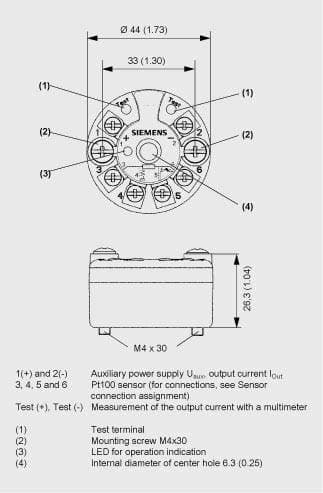 SITRANS TH200/TH300, dimensions and pin assignment, dimensions in mm (inch)
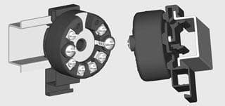 SITRANS TH200/TH300, mounting of transmitter on DIN rail
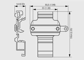 DIN rail adaptor, dimensions in mm (inch)
Схема подключения
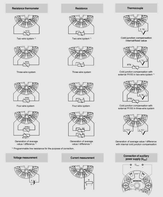 SITRANS TH200/TH300, sensor connection assignment
Заказные данные [PDF]
.
Для просмотра информации в формате PDF необходимо установить Adobe Acrobat Reader.

Заказные данные
| Заказной № | Описание | Вес (кг) | Доставка | Мин. зак. (шт) |
|---|---|---|---|---|
| 7NG3211-1AN00 | ИЗМЕРИТЕЛЬНЫЙ ПРЕОБРАЗОВАТЕЛЬ ТЕМПЕРАТУРЫ SITRANS TH200, ДЛЯ МОНТАЖА В ГОЛОВКУ СЕНСОРА, 2-Х ПРОВОДНЫЙ, 4-20 MA, ПРОГРАММИРУЕМЫЙ, С ГАЛЬВАНИЧЕСКОЙ РАЗВЯЗКОЙ, ВЗРЫВОЗАЩИТА (ATEX): ИСКРОБЕЗОПАСНОЕ ИСПОЛНЕНИЕ И ДЛЯ ЗОНЫ 2, БЕЗ РУКОВОДСТВА | 0.08 | 3 - 5 недель (A) | 1 |
| 7NG3211-1BN00 | ИЗМЕРИТЕЛЬНЫЙ ПРЕОБРАЗОВАТЕЛЬ ТЕМПЕРАТУРЫ SITRANS TH200, ДЛЯ МОНТАЖА В ГОЛОВКУ СЕНСОРА, 2-Х ПРОВОДНЫЙ, 4-20 MA, ПРОГРАММИРУЕМЫЙ, С ГАЛЬВАНИЧЕСКОЙ РАЗВЯЗКОЙ, ВЗРЫВОЗАЩИТА (CFMUS): ИСКРОБЕЗОПАСНОЕ ИСПОЛНЕНИЕ И ДЛЯ ЗОНЫ 2, БЕЗ РУКОВОДСТВА | 0.08 | 3 - 5 недель (A) | 1 |
| 7NG3211-1NN00 | ИЗМЕРИТЕЛЬНЫЙ ПРЕОБРАЗОВАТЕЛЬ ТЕМПЕРАТУРЫ SITRANS TH200, ДЛЯ МОНТАЖА В ГОЛОВКУ СЕНСОРА, 2-Х ПРОВОДНЫЙ, 4-20 MA, ПРОГРАММИРУЕМЫЙ, С ГАЛЬВАНИЧЕСКОЙ РАЗВЯЗКОЙ, БЕЗ ВЗРЫВОЗАЩИТЫ, БЕЗ РУКОВОДСТВА | 0.08 | 3 - 5 недель (A) | 1 |
Аксессуары
| Заказной № | Описание | Вес (кг) | Доставка | Мин. зак. (шт) |
|---|---|---|---|---|
| 7NG3092-8KA | ADAPTER FOR RAIL MOUNTING OF HEAD MOUNTED TRANSMITTERS (5 PCS.) | 0.06 | 3 - 5 недель (A) | 1 |
| 7NG3092-8KM | МОДЕМ С ИНТЕРФЕЙСОМ RS232 ДЛЯ ПАРАМЕТРИРОВАНИЯ ИЗМЕРИТЕЛЬНЫХ ПРЕОБРАЗОВАТЕЛЕЙ ТЕМПЕРАТУРЫ SITRANS TH100/200, С ПРОГРАММНЫМ ОБЕСПЕЧЕНИЕМ SIPROM T | 0.43 | 3 - 5 недель (A) | 1 |
| 7NG3092-8KU | МОДЕМ С USB- ИНТЕРФЕЙСОМ ДЛЯ ПАРАМЕТРИРОВАНИЯ ИЗМЕРИТЕЛЬНЫХ ПРЕОБРАЗОВАТЕЛЕЙ ТЕМПЕРАТУРЫ SITRANS TH100/200, С ПРОГРАММНЫМ ОБЕСПЕЧЕНИЕМ SIPROM T | 0.3 | 3 - 5 недель (A) | 1 |
| A5E00364512 | CD-ROM FOR TEMPERATURE MEASURE- MENT DEVICES WITH DOKUMENTATION AND SOFTWARE SIPROM T | 0 | 3 - 5 недель (A) | 1 |