
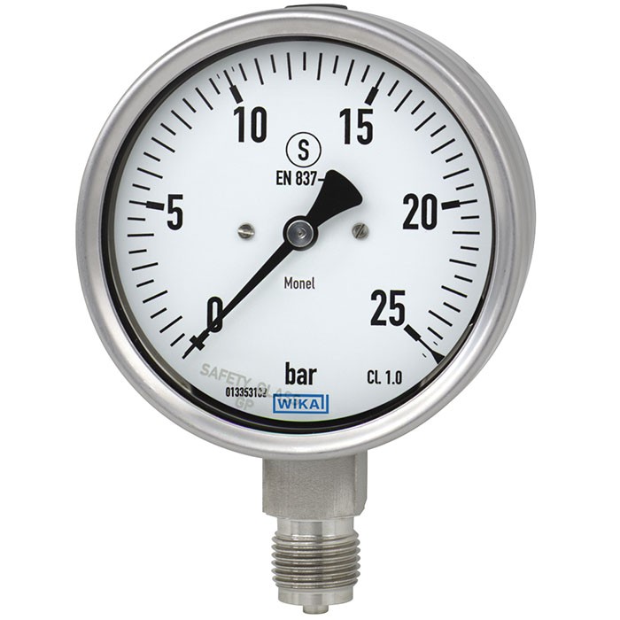
Манометр із трубкою Бурдона
Опис
Моделі 262 і 263 — це високоякісні манометри з трубкою Бурдона з контактуючими з вимірюваним середовищем деталями з надзвичайно корозійностійкого сплаву Monel.
Застосування високоякісних матеріалів і міцна конструкція орієнтовані на застосування в хімічній та процесній інженерії для середовищ із особливо агресивними кислотами або лугами. Прилад придатний для рідинних і газових середовищ, також у агресивних умовах.
Діапазони шкали від 0 … 0,6 до 0 … 1,000 bar [0 ... 10 до 0 ... 15,000 psi] забезпечують необхідні межі вимірювання для широкого спектра застосувань.
Для отримання додаткових допусків див. сторінку 6
Манометр із трубкою Бурдона, модель 262.30, NS 100 [4 " ]
Запобіжне виконання складається з небиткого (незісколювального) вікна, суцільної перегородки між вимірювальною системою та шкалою, а також із запобіжного відкидного елемента (blow-out back). У разі відмови користувача захищено з фронтального боку, оскільки середовище або компоненти можуть викидатися лише через задню частину корпусу.
Для важких умов експлуатації (наприклад, вібрацій) всі прилади також доступні з опційним заповненням рідиною.
QR-код на шкалі дає змогу легко й у довгостроковій перспективі отримувати з інтернету інформацію, специфічну для приладу, зокрема серійний номер, номер замовлення, сертифікати та інші дані про продукт.
Особливості
- З наповненням корпусу (модель 263) для застосувань з високими динамічними навантаженнями тиску та вібраціями
- Моделі 262.30 та 263.30: безпечне виконання із суцільною захисною стінкою (Solidfront) відповідно до вимог EN 837-1 та ASME B40.100
- Придатність для особливо агресивних середовищ завдяки дуже високій корозійній стійкості
- Версія EMICOgauge для запобігання фугативним викидам
- QR-код на шкалі веде до інформації про конкретний прилад
Питання та відповіді
Які діапазони вимірювання доступні?
Діапазони шкали — від -1 … 0 bar до 0 … 1.000 bar, включно з комбінованими варіантами, наприклад -1 … 24 bar.
Наскільки точний цей манометр?
Клас точності 1.6 відповідно до стандарту EN 837-1.
Чим відрізняються моделі 262 і 263?
Модель 263 має заповнення корпусу рідиною для застосувань із високими динамічними навантаженнями тиску та вібраціями; модель 262 — сухе виконання.
Що означає безпечне виконання моделей 262.30 і 263.30?
Це виконання Solidfront із суцільною перегородкою між вимірювальною системою та шкалою, небитким вікном і запобіжним відкидним елементом на задній частині корпусу; конструкція відповідає вимогам EN 837-1 та ASME B40.100.
Для яких середовищ підходить прилад?
Для газоподібних і рідких агресивних середовищ, що не є високов'язкими чи кристалізуючими; деталі, що контактують із середовищем, виготовлені з Monel 400 (2.4360), ущільнення — FKM або PEEK.
Чи придатний прилад для сірководневих (sour gas) застосувань?
Так, прилад придатний для sour gas застосувань відповідно до NACE MR0175/ISO 15156.
Які температури експлуатації допускаються?
Температура середовища: -40 … +200 °C; температура навколишнього середовища: -40 … +60 °C.
Які варіанти присоединения до процесу доступні?
G 1/8 B, G 1/4 B, G 1/2 B, R 1/4, R 1/2, M12 x 1.5, M20 x 1.5, а також 1/8 NPT, 1/4 NPT і 1/2 NPT.
| Модель | 262.50, 263.50, 262.30, 263.30 |
| Сімейство | 262 |
| Підтип | Mechanical pressure gauge |
| Діапазон тиску | 0…0.6 bar · 0…1 bar · 0…1.6 bar · 0…2.5 bar · 0…4 bar · 0…6 bar · 0…10 bar · 0…16 bar · 0…25 bar · 0…1000 bar · -1…0 bar · -1…0.6 bar · -1…1.5 bar · -1…3 bar · -1…9 bar · -1…15 bar · -1…24 bar · 0…40 bar · 0…60 bar · 0…100 bar · 0…160 bar · 0…250 bar · 0…400 bar · 0…600 bar · -0.6…0 bar · -1…5 bar |
| Клас точності | 1.6 |
| Стандарт точності | EN 837-1 |
| Технологічне приєднання | M12 x 1.5M20 x 1.5R ¼R ½G ⅛ BG ¼ BG ½ B¼ NPT⅛ NPT½ NPTG 1/8 BG 1/4 BG 1/2 BR 1/4R 1/21/4 NPT1/8 NPT1/2 NPT |
| Темп. процесу | −40…+200 °C |
| Матеріал корпусу | Stainless steel 1.4301 (304), Stainless steel 1.4571 (316Ti), 1.4301 (304), 1.4571 (316Ti) |
| Матеріал змочуваних частин | Monel 400 (2.4360) |
| Матеріал ущільнення | FKM, PEEK |
| Темп. навколишнього середовища | −40…+60 °C |
| Ступінь захисту IP | IP65 |
| Вага | 0.16 kg |
| Сертифікати | CEUKCAEACCRNDNVPAC ChinaPAC UkrainePAC UzbekistanMChSNACE MR0175/ISO 15156 |
| Вибухозахист | II 2G Ex h IIC T6 ... T1 Gb XII 2D Ex h IIIC T85°C ... T450°C Db XII 2G Ex h IIC T6...T1 Gb XDII 2D Ex h IIC T85℃...T450℃ DbX |
| Діаметр шкали | 100 mm |
| Мови datasheet | EN, DE |
| Basic information | |
|---|---|
| Standard | ■ EN 837-1 ■ ASME B40.100 |
| For information on the 'Selection, installation, handling and operation of pressure gauges', see technical information IN 00.05. | |
| Further version | ■ For oxygen, oil- and grease-free ■ Per NACE 1) MR0175 / ISO 15156, use in H₂S-containing environments in oil and gas production ■ With pre-volume deflagration flame arrester 2) for mounting to zone 0 (EPL Ga); model 910.21; see data sheet AC 91.02 ■ EMICOgauge, to avoid fugitive emissions; instrument hook-up with instrumenta- tion valves →See page 10 |
| Nominal size (NS) | ■ Ø63 mm[2 ½"] ■ Ø100 mm[4"] ■ Ø160 mm[6"] |
| Connection location | ■ Lower mount (radial) ■ Lower back mount 3) |
| Window | Laminated safety glass (NS 63 [2 ½"]: polycarbonate) |
| Case | |
| Model 262.50, 263.50 | Safety level 'S1' per EN 837-1: with blow-out device |
| Model 262.30, 263.30 | Safety level 'S3' per EN 837-1: with solid baffle wall and blow-out back |
| Internal pressure compensation | For scale ranges ≤ 0 ...16 bar [≤ 0 ...300 psi] the case can be vented and resealed |
| Material | ■ Stainless steel 1.4301 (304) ■ Stainless steel 1.4571 (316Ti) |
| Ring | Bayonet bezel, stainless steel |
| Mounting | ■ Without ■ Panel mounting flange, stainless steel ■ Panel mounting flange, polished stainless steel ■ Model 262.50, 263.50: surface mounting flange, stainless steel ■ Model 262.30, 263.30: surface mounting lugs on the back, stainless steel |
| Case filling (model 263.50, 263.30) | ■ Without ■ Glycerine ■ Glycerine-water mixture for NS 100 [4"] and 160 [6"] with scale range ≤ 0 ... 2.5 bar [≤ 0 ... 40 psi] or for NS 63 [2 ½"] with scale range ≤ 0 ... 4 bar [≤ 0 ... 60 psi] ■ Silicone oil |
| Movement | ■ Stainless steel ■ everlast ® version |
| Type of measuring element | Bourdon tube, C-type or helical type |
|---|---|
| Material | Monel 400 (2.4360) |
| Leak tightness | ■ Helium tested, leakage rate: < 5∙10 -3 mbar l/s ■ Helium tested, leakage rate: < 1∙10 -6 mbar l/s |
| Accuracy class | ||
|---|---|---|
| NS 63 [2 ½"] | EN 837-1 | Class 1.6 |
| ASME B40.100 | ±2 %of measuring span (grade A) | |
| NS 100 [4"], 160 [6"] | EN 837-1 | Class 1.0 |
| ASME B40.100 | ±1 %of measuring span (grade 1A) | |
| Temperature error | On deviation from the reference conditions at the measuring system: ≤ ±0.4 %per 10 °C [≤ ±0.4 %per 18 °F] of full scale value | |
| Reference conditions | ||
| Ambient temperature | +20 °C [68 °F] |
| bar | |
|---|---|
| 0 ... 0.6 1) | 0 ... 40 |
| 0 ... 1 | 0 ... 60 |
| 0 ... 1.6 | 0 ... 100 |
| 0 ... 2.5 | 0 ... 160 |
| 0 ... 4 | 0 ... 250 |
| 0 ... 6 | 0 ... 400 |
| 0 ... 10 | 0 ... 600 |
| 0 ... 16 | 0 ... 1,000 |
| 0 ... 25 | - |
Переглянути всі (20)
| 0 ... 60 1) | 0 ... 4,000 |
|---|---|
| 0 ... 100 | 0 ... 6,000 |
| 0 ... 160 | 0 ... 10,000 |
| 0 ... 250 | 0 ... 16,000 |
| 0 ... 400 | 0 ... 25,000 |
| 0 ... 600 | 0 ... 40,000 |
| 0 ... 1,000 | 0 ... 60,000 |
| 0 ... 1,600 | 0 ... 100,000 |
| 0 ... 2,500 | - |
| psi | |
|---|---|
| 0 ... 10 1) | 0 ... 1,000 |
| 0 ... 15 | 0 ... 1,500 |
| 0 ... 30 | 0 ... 2,000 |
| 0 ... 60 | 0 ... 3,000 |
| 0 ... 100 | 0 ... 4,000 |
| 0 ... 160 | 0 ... 5,000 |
| 0 ... 200 | 0 ... 6,000 |
| 0 ... 300 | 0 ... 7,500 |
| 0 ... 400 | 0 ... 10,000 |
| 0 ... 600 | 0 ... 15,000 |
| 0 ... 800 | - |
| 0 ... 0.6 1) | 0 ... 40 |
|---|---|
| 0 ... 1 | 0 ... 60 |
| 0 ... 1.6 | 0 ... 100 |
| 0 ... 2.5 | 0 ... 160 |
| 0 ... 4 | 0 ... 250 |
| 0 ... 6 | 0 ... 400 |
| 0 ... 10 | 0 ... 600 |
| 0 ... 16 | 0 ... 1,000 |
| 0 ... 25 | - |
| 0 ... 0.06 1) | 0 ... 4 |
|---|---|
| 0 ... 0.1 | 0 ... 6 |
| 0 ... 0.16 | 0 ... 10 |
| 0 ... 0.25 | 0 ... 16 |
| 0 ... 0.4 | 0 ... 25 |
| 0 ... 0.6 | 0 ... 40 |
| 0 ... 1 | 0 ... 60 |
| 0 ... 1.6 | 0 ... 100 |
| 0 ... 2.5 | - |
| bar | |
|---|---|
| -0.6 ... 0 1) | -1 ...+5 |
| -1 ... 0 | -1 ...+9 |
| -1 ... +0.6 | -1 ...+15 |
| -1 ... +1.5 | -1 ...+24 |
| -1 ...+3 | - |
| -60 ... 0 1) | -100 ...+500 |
|---|---|
| -100 ... 0 | -100 ...+900 |
| -100 ...+60 | -100 ... +1,500 |
| -100 ...+150 | -100 ... +2,400 |
| -100 ...+300 | - |
| Further details on: Scale ranges | |
|---|---|
| Unit | ■ bar ■ psi ■ kg/cm² ■ kPa ■ MPa |
| Increased overload safety | ■ Without ■ 2 times ■ 3 times ■ 4 times ■ 5 times |
| Vacuum resistance | ■ Without ■ Vacuum-resistant to -1 bar |
| Dial | |
| Scale colour | Black |
| Material | Aluminium |
| Customer-specific version | Other scales or customer-specific dials, e.g. with red mark, circular arcs or circular sectors, on request |
| Pointer | |
| Instrument pointer | Aluminium, black |
| Mark pointer / Drag pointer | ■ Without ■ Red mark pointer on dial, fixed ■ Red mark pointer on window, adjustable ■ Mark pointer on bayonet bezel, adjustable ■ Red drag pointer on window, adjustable |
| Pointer stop pin | ■ Without ■ At zero point (only for NS 63 [2 ½"]) ■ At 6 o'clock (only for NS 100 [4"], 160 [6"]) |
| -0.06 ... 0 1) | -0.1 ... +0.5 |
|---|---|
| -0.1 ... 0 | -0.1 ... +0.9 |
| -0.1 ... +0.06 | -0.1 ... +1.5 |
| -0.1 ... +0.15 | -0.1 ... +2.4 |
| -0.1 ... +0.3 | - |
| -30 inHg ... 0 | -30 inHg ...+100 |
|---|---|
| -30 inHg ...+15 | -30 inHg ...+160 |
| -30 inHg ...+30 | -30 inHg ...+200 |
| -30 inHg ...+60 | -30 inHg ...+300 |
| Process connection | |
|---|---|
| Standard | ■ EN 837-1 ■ ISO 7 ■ ANSI/B1.20.1 |
| Size | |
| EN 837-1 | ■ G⅛B,male thread ■ G¼B,male thread ■ G½B,male thread ■ M12 x 1.5, male thread ■ M20 x 1.5, male thread |
| ISO 7 | ■ R ¼, male thread ■ R ½, male thread |
| ANSI/B1.20.1 | ■ ¼NPT, male thread ■ ½NPT, male thread |
| Restrictor | ■ Without ■ ∅0.6 mm[0.024"], Monel |
| Material (wetted) | |
| Process connection | Monel 400 (2.4360) |
| Bourdon tube | Monel 400 (2.4360) |
| Medium temperature | ||
|---|---|---|
| Instruments without filling | -40 ...+200 °C [-40 ...+392 °F] | |
| Instruments with glycerine filling | -20 ...+100 °C [-4 ...+212 °F] | |
| Instruments with silicone oil filling | -40 ...+100 °C [-40 ...+212 °F] | |
| Ambient temperature | ||
| Instruments without filling or with silicone oil filling | -40 ...+60 °C [-40 ...+140 °F] | |
| Instruments with glycerine filling | -20 ...+60 °C [-4 ...+140 °F] | |
| Pressure limitation | ||
| NS 63 [2 ½"] | Steady | 3/4 x full scale value |
| Fluctuating | 2/3 x full scale value | |
| Short time | Full scale value | |
| NS 100 [4"], 160 [6"] | Steady | Full scale value |
| Fluctuating | 0.9 x full scale value | |
| Short time | 1.3 x full scale value | |
| Ingress protection per IEC/EN 60529 | ■ IP65 ■ IP66 |
| Logo | Description | Region |
|---|---|---|
| EU declaration of conformity Pressure Equipment Directive PS > 200 bar, module A, pressure accessory | European Union | |
| UKCA Pressure equipment (safety) regulations | United Kingdom | |
| - | CRN Safety (e.g. electr. safety, overpressure, ...) | Canada |
| Logo | Description | Region |
|---|---|---|
| EU declaration of conformity ATEX directive Hazardous areas - Ex h Gas II 2G Ex h IIC T6 ...T1 Gb X Dust II 2D Ex h IIIC T85°C ...T450°C Db X | European Union | |
| UKCA Equipment and protective systems intended for use in potentially explosive atmospheres regulations | United Kingdom | |
| EAC Hazardous areas | Eurasian Economic Community | |
| Ex Ukraine Hazardous areas | Ukraine | |
| PAC Kazakhstan Metrology, measurement technology | Kazakhstan | |
| - | MChS Permission for commissioning | Kazakhstan |
| - | PAC Ukraine Metrology, measurement technology | Ukraine |
| PAC Uzbekistan Metrology, measurement technology | Uzbekistan | |
| - | PAC China Metrology, measurement technology | China |
| DNV Ships, shipbuilding (e.g. offshore) | International |
| Logo | Description |
|---|---|
| - | Emission protection in accordance with TA-Luft (VDI 2440) 1) |
| - | Pressure Equipment Directive (PED) for maximum allowable pressure PS ≤ 200 bar |
| Certificates | ■ 2.2 test report per EN 10204 (e.g. state-of-the-art manufacturing, indication accuracy) ■ 3.1 inspection certificate per EN 10204 (e.g. material proof for wetted metal parts, indication accuracy) ■ PCA calibration certificate, traceable and accredited in accordance with ISO/IEC 17025 ■ Calibration certificate by a national accreditation body, traceable and accredited in accordance with ISO/IEC 17025 on request |
|---|---|
| Recommended calibration interval | 1 year (dependent on conditions of use) |
| NS | G | Dimensions in mm[in] | ||||||||
|---|---|---|---|---|---|---|---|---|---|---|
| h ±1 | a | b | D1 | D2 | i | j | k | SW | ||
| 63 [2 ½"] | G¼B | 54 [2.13] | 9.5 [0.37] | 33 [1.30] | 63 [2.48] | 62 [2.44] | 6 [0.24] | 10 [0.39] | 15 [0.59] | 14 [0.55] |
| G⅛B | 51 [2.01] | 9.5 [0.37] | 33 [1.30] | 63 [2.48] | 62 [2.44] | 6 [0.24] | 10 [0.39] | 15 [0.59] | 14 [0.55] | |
| M12 x 1.5 | 54 [2.13] | 9.5 [0.37] | 33 [1.30] | 63 [2.48] | 62 [2.44] | 6 [0.24] | 10 [0.39] | 15 [0.59] | 14 [0.55] | |
| 100 [4"] | G¼B | 80 [3.15] | 15.5 [0.61] | 49.5 [1.95] | 101 [3.98] | 99 [3.90] | 6.5 [0.26] | 14.5 [0.57] | 22.5 [0.89] | 22 [0.87] |
| G½B | 87 [3.43] | 15.5 [0.61] | 49.5 [1.95] | 101 [3.98] | 99 [3.90] | 6.5 [0.26] | 14.5 [0.57] | 22.5 [0.89] | 22 [0.87] | |
| M12 x 1.5 | 80 [3.15] | 15.5 [0.61] | 49.5 [1.95] | 101 [3.98] | 99 [3.90] | 6.5 [0.26] | 14.5 [0.57] | 22.5 [0.89] | 22 [0.87] | |
| M20 x 1.5 | 87 [3.43] | 15.5 [0.61] | 49.5 [1.95] | 101 [3.98] | 99 [3.90] | 6.5 [0.26] | 14.5 [0.57] | 22.5 [0.89] | 22 [0.87] | |
| 160 [6"] | G¼B | 111 [4.37] | 15.5 [0.61] | 51.5 [2.03] 1) | 161 [6.34] | 159 [6.26] | 6.5 [0.26] | 14.5 [0.57] | 22.5 [0.89] | 22 [0.87] |
| G½B | 118 [4.65] | 15.5 [0.61] | 51.5 [2.03] 1) | 161 [6.34] | 159 [6.26] | 6.5 [0.26] | 14.5 [0.57] | 22.5 [0.89] | 22 [0.87] | |
| M12 x 1.5 | 111 [4.37] | 15.5 [0.61] | 51.5 [2.03] 1) | 161 [6.34] | 159 [6.26] | 6.5 [0.26] | 14.5 [0.57] | 22.5 [0.89] | 22 [0.87] | |
| M20 x 1.5 | 118 [4.65] | 15.5 [0.61] | 51.5 [2.03] 1) | 161 [6.34] | 159 [6.26] | 6.5 [0.26] | 14.5 [0.57] | 22.5 [0.89] | 22 [0.87] |
Не знайшли відповіді у документації? Інженер відповість впродовж робочого дня.
Запитати інженера →1 стандартних артикулів сімейства 262
Якщо знаєте код — оберіть напряму. Якщо ні — користуйтесь конфігуратором у режимі «01».