
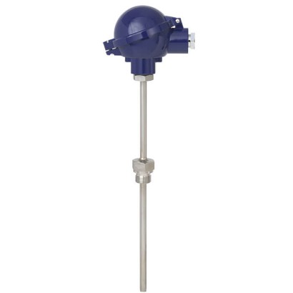
Резьбовой термометр сопротивления
Описание
Сопротивленческие термометры этой серии предназначены для непосредственного ввинчивания в процесс, главным образом в ёмкости и трубопроводы. Они подходят для жидких и газообразных сред при умеренных механических нагрузках и при нормальных химических условиях.
Термокарман из нержавеющей стали полностью приварен и ввинчен в соединительную головку. Сменный измерительный вставной элемент можно извлечь без демонтажа всего зонда из установки. Это позволяет выполнять осмотр, мониторинг измерительного оборудования или, при необходимости проведения работ по обслуживанию, замену при работающей установке. (Исключения составляют приборы с перфорированным термокарманом для измерения температуры в воздуховодах).
Для получения дополнительных допусков см. стр. 18
Особенности
- Диапазоны измерений чувствительного элемента от -196 ... +600 °C [-320 ... +1,112 °F]
- Со встроенной защитной гильзой
- Пружинный измерительный вкладыш (сменный)
- Взрывозащищённые исполнения доступны для многих типов допусков
Вопросы и ответы
Какой диапазон температур измеряет TR10-C?
Диапазон температуры среды составляет от -196 до +600 °C; доступны также другие варианты диапазонов, например -50 … +500 °C или 0 … +150 °C.
Какой точности можно ожидать от прибора?
Чувствительный элемент Pt100 класса A с допуском ±(0,30 + 0,0050 |t|) °C.
Какие варианты присоединения к процессу предусмотрены?
Резьбовое, приварное и через цанговый зажим; резьбы M20 x 1.5, ½ NPT и 3/4 NPT.
Для каких сред подходит этот термометр?
Прибор предназначен для жидких и газообразных сред при умеренных механических нагрузках и нормальных химических условиях.
Какая взрывозащита доступна?
Доступны версии Ex i (газ, зоны 0, 1, 2), Ex i (пыль, зоны 20, 21, 22), Ex e (зоны 1, 2), Ex t (зоны 21, 22) и Ex nA (зона 2), а также исполнения Ex ia/ib/ic IIC и IIIC для газов и пыли, включая EAC Ex ia/ib IIC.
Можно ли заменить измерительную вставку без остановки процесса?
Да, сменный измерительный вставной элемент с пружинной фиксацией извлекается без демонтажа всего зонда из установки. Исключение составляют приборы с перфорированным термокарманом для воздуховодов.
Чем TR10-C отличается от других моделей серии TR10?
TR10-C имеет полностью приваренный термокарман из нержавеющей стали, который ввинчен в соединительную головку, что отличает его от конструкций без защитной гильзы.
Какой выходной сигнал поддерживает прибор?
4-20 mA (питание по токовой петле) с опциональной интеграцией преобразователя и поддержкой протокола HART.
Соберите TR10-C под свою задачу
Артикул собирается автоматически. Если сомневаетесь — напишите инженеру; подскажем по параметрам линии.
- Стандарт взрывозащитыБез
- Маркировка взрывозащитыБез
- Маркировка взрывозащитыБез
- Чувствительный элемент1 x Pt100, 3-проводной
- Класс точности сенсораКласс B, МЭК 60751
- Рабочий диапазон для выбранного типа сенсора термометра сопротивления-50...+250°C
- Соединительная головка / корпусГоловка BSZ, алюминий, круглая форма, откидная крышка
- Кабельный вводСтандартный кабельный ввод для головок A-/B-/J-
- Резьба кабельного вводаM20 x 1.5
- ПреобразовательБез (с клеммным блоком)
- Информация о преобразователеБез
- Присоединение к удлинительной шейкеM24 x 1,5
- Защитная гильзаПрямая, резьбовая, форма 2G по DIN 43772
- Диаметр защитной гильзы—
- Присоединение к процессу—
- Материал защитной гильзыНержавеющая сталь 1.4571
- Глубина погружения [A]—
- Длина шейки [MH/N]130
- Требования к механической устойчивостиБез
- Доп. опции для защитной гильзыБез
- СертификатыБез
Завершите конфигурацию
Выберите все параметры, чтобы отправить запрос.
| Модель | TR10-C |
| Серия | TR10 |
| Подтип | Resistance thermometer |
| Диапазон температуры | −196…+600 °C · −50…+500 °C · −50…+250 °C · −30…+300 °C · −196…+450 °C · +0…+150 °C · −50…+200 °C · −100…+450 °C |
| Класс точности | ±(0.30 + 0.0050 |t|) °C |
| Уровень функциональной безопасности (SIL) | SIL 2 |
| Технологическое присоединение | ThreadedWeld-onCompression fittingM20 x 1.5½NPT1/2 NPT3/4 NPT |
| Темп. процесса | −196…+600 °C |
| Выходной сигнал | 4-20mA · HART |
| Питание | Loop powered (4-20 mA) |
| Электр. соединение | M20 x 1.5, ½ NPT |
| Материал зонда | 1.4571, 316L, Stainless steel |
| Материал защитной гильзы | Stainless steel, 1.4571, 316L |
| Темп. окружающей среды | −40…+80 °C |
| Степень защиты IP | IP65 |
| Сертификаты | CEEACRoHSREACHNACENAMURSILDAkkSINMETROCCCNEPSIKCPACMChS |
| Взрывозащита | Ex i (gas) Zone 0, 1, 2Ex i (dust) Zone 20, 21, 22Ex e (gas) Zone 1, 2Ex t (dust) Zone 21, 22Ex nA (gas) Zone 2Ex ia IIIC T6...T1 GaEx ib IIIC T6...T1 GbEx ic IIIC T6...T1 GcEx ia IIC T200°C DaEx ib IIC T125°C DbEx ec IIC T6...T1 GbEx tc IIC T135°C DcEAC Ex ia IIC T6...T1 GaEAC Ex ib IIC T6...T1 GbEx ia IIC T200...T65°C Da |
| Тип сенсора | Pt100 |
| Класс сенсора | A |
| Диаметр зонда | 3 mm |
| Защитная гильза | Да |
| Форма защитной гильзы | Form 2F |
| Языки datasheet | EN, DE |
| Model | Material | Thread size of cable inlet | Ingress protection (max.) 1) 2) IEC/EN 60529 | Cap | Surface | Connection to neck tube | |
|---|---|---|---|---|---|---|---|
| BSZ, BSZ-K | BSZ | Aluminium | ■ M20 x 1.5 ■ ½NPT | IP65 | Spherical hinged cover with cylinder head screw | Blue, painted (RAL 5022) | M24 x 1.5 |
| BSZ-H, BSZ-HK BSZ-K | BSS Plastic | BSS-H ■ M20 x 1.5 ■ ½NPT | BVS IP65 | BVS (NuG) Spherical hinged cover with cylinder head screw | 1/4000 Black | 5/6000 M24 x 1.5 | |
| BSZ-H, BSZ-HK | BSZ-H | Aluminium | ■ M20 x 1.5 ■ ½NPT | IP65 | Raised hinged cover with cylinder head screw | Blue, painted (RAL 5022) | M24 x 1.5 |
| BSS BSZ-H (2 x cable outlet) | BSS-H Aluminium | BVS ■ 2 x M20 x 1.5 ■ 2x½NPT | BVS (NuG) IP65 | 5/6000 1/4000 Raised hinged cover with cylinder head screw | 7/8000 Blue, painted (RAL 5022) | 7/8000 DIH50 M24 x 1.5 | |
| BSZ-H / DIH10 3) | Aluminium | ■ M20 x 1.5 ■ ½NPT | IP65 | Raised hinged cover with cylinder head screw | Blue, painted (RAL 5022) | M24 x 1.5 | |
| BSZ-H /TND 4) | Aluminium | ■ M20 x 1.5 ■ ½NPT | IP65 | Raised hinged cover with cylinder head screw | Blue, painted (RAL 5022) | M24 x 1.5 | |
| BSZ-HK | Plastic | ■ M20 x 1.5 ■ ½NPT | IP65 | Raised hinged cover with cylinder head screw | Black | M24 x 1.5 | |
| BS | Aluminium | ■ M20 x 1.5 ■ ½NPT | IP65 | Flat cover with 2 screws | Blue, painted (RAL 5022) | M24 x 1.5 | |
| BS | BSZ, BSZ-K BSS | BSZ-H, BSZ-HK Aluminium | BSS ■ M20 x 1.5 ■ ½NPT | BSS-H IP65 | BVS Spherical hinged cover with clamping lever | BVS (NuG) Blue, painted (RAL 5022) | 1/4000 M24 x 1.5 |
| BSS | BSS-H BSS-H | BVS Aluminium | BVS (NuG) ■ M20 x 1.5 ■ ½NPT | 1/4000 IP65 | 7/8000 5/6000 Raised hinged cover with clamping lever | 7/8000 DIH50 andere Blue, painted (RAL 5022) | Anschlussgehäuse M24 x 1.5 |
| BSS-H | BVS BVS | BVS (NuG) Stainless steel | 1/4000 M20 x 1.5 | 5/6000 IP65 | 7/8000 DIH50 7/8000 Precision-cast screw- on lid | andere Anschlussgehäuse Natural finish, electropol- ished | KN4-P M24 x 1.5 |
| Model | Explosion protection | |||||
|---|---|---|---|---|---|---|
| Without | Ex i (gas) Zone 0, 1, 2 | Ex i (dust) Zone 20, 21, 22 | Ex e (gas) Zone 1, 2 | Ex t (dust) Zone 21, 22 | Ex nA (gas) Zone 2 | |
| BSZ | x | x | x | x 1) | x 1) | x 2) |
| BSZ-K | x | x | - | - | - | - |
| BSZ-H | x | x | x | x 1) | x 1) | x 2) |
| BSZ-H (2 x cable outlet) | x | x | x | x 1) | x 1) | x 2) |
| BSZ-H / DIH10 3) | x | x | - | - | - | - |
| BSZ-H /TND 4) | x | x | - | - | - | - |
| BSZ-HK | x | x | - | - | - | - |
| BS | x | x | x | - | - | - |
| Model | Explosion protection | |||||
|---|---|---|---|---|---|---|
| Without | Ex i (gas) Zone 0, 1, 2 | Ex i (dust) Zone 20, 21, 22 | Ex e (gas) Zone 1, 2 | Ex t (dust) Zone 21, 22 | Ex nA (gas) Zone 2 | |
| BSS | x | x | - | - | - | - |
| BSS-H | x | x | - | - | - | - |
| BVS | x | x | - | - | - | - |
| Model | Material | Thread size of cable inlet | Ingress protection (max.) 1) 2) IEC/EN 60529 | Cap | Surface | Connection to neck tube | |
|---|---|---|---|---|---|---|---|
| KN4-A | Aluminium | ■ ½NPT ■ M20 x 1.5 | IP65 | Screw-on lid | Blue, painted (RAL 5022) | M24 x 1.5 |
Смотреть все (20)
| Model | Explosion protection | |||||
|---|---|---|---|---|---|---|
| Without | Ex i (gas) Zone 0, 1, 2 | Ex i (dust) Zone 20, 21, 22 | Ex e (gas) Zone 1, 2 | Ex t (dust) Zone 21, 22 | Ex nA (gas) Zone 2 | |
| KN4-A | x | x | - | - | - | - |
| Cable inlet | Colour Max. ingress 1) | protection DIN EN IEC 60529 | Thread size of cable inlet | Min./Max. ambient temperature |
|---|---|---|---|---|
| Standard cable inlet 2) | Natural finish | IP65 | M20 x 1.5 | -40 ...+80 °C [-40 ...+176 °F] |
| Plastic cable gland (cable Ø6...10 mm) 2) | ■ Black ■ Grey | IP66 | ■ M20 x 1.5 ■ ½NPT | -40 ...+80 °C [-40 ...+176 °F] |
| Plastic cable gland (cable Ø 6 ... 10 mm), Ex e 2) | ■ Light blue ■ Black | IP66 | ■ M20 x 1.5 ■ ½NPT | ■ -20 ...+80 °C [-4 ...+176 °F] ■ -40 ...+70 °C [-40 ...+158 °F] |
| Nickel-plated brass cable gland (cable Ø 6 ... 12 mm) | Natural finish | IP66 | ■ M20 x 1.5 ■ ½NPT | -60 3) / -40 ...+80 °C [-76 / -40 ...+176 °F] |
| Nickel-plated brass cable gland (cable Ø 6 ... 12 mm), Ex e | Natural finish | IP66 | ■ M20 x 1.5 ■ ½NPT | -60 3) / -40 ...+80 °C [-76 / -40 ...+176 °F] |
| Stainless steel cable gland (cable Ø 7 ... 12 mm) | Natural finish | IP66 | ■ M20 x 1.5 ■ ½NPT | -60 3) / -40 ...+80 °C [-76 / -40 ...+176 °F] |
| Stainless steel cable gland (cable Ø 7 ... 12 mm), Ex e | Natural finish | IP66 | ■ M20 x 1.5 ■ ½NPT | -60 3) / -40 ...+80 °C [-76 / -40 ...+176 °F] |
| Plain threaded | - | IP00 | ■ M20 x 1.5 ■ ½NPT | - |
| 2 x plain threaded 4 ) | - | IP00 | ■ 2 x M20 x 1.5 ■ 2x½NPT | - |
| Built-in connector (male) M12 (4-pin) Built-in connector (female) M12 1 (4-pin) | - | IP65 | M20 x 1.5 | -40 ...+80 °C [-40 ...+176 °F] |
| Sealing plugs for shipping | Transparent | - | ■ M20 x 1.5 ■ ½NPT | -40 ...+80 °C [-40 ...+176 °F] |
| Cable inlet | Explosion protection | |||||
|---|---|---|---|---|---|---|
| With- out | Ex i (gas) Zone 0, 1, 2 | Ex i (dust) Zone 20, 21, 22 | Ex e (gas) Zone 1, 2 | Ex t (dust) Zone 21, 22 | Ex nA (gas) Zone 2 | |
| Standard cable inlet 1) 3) | x | x | - | - | - | - |
| Plastic cable gland 1) | x | x | - | - | - | - |
| Plastic cable gland (light blue), Ex e 1) | x | x | x | - | - | - |
| Plastic cable gland (black), Ex e 1) | x | x | x | x | x | x |
| Brass cable gland, nickel-plated | x | x | x | - | - | - |
| Brass cable gland, nickel-plated, Ex e | x | x | x | x | x | x |
| Stainless steel cable gland | x | x | x | - | - | - |
| Stainless steel cable gland, Ex e | x | x | x | x | x | x |
| Plain threaded | x | x | x 5) | x 5) | x 5) | x 5) |
| 2 x plain threaded 2) | x | x | x 5) | x 5) | x 5) | x 5) |
| Junction box M12 x 1 (4-pin) 3) | x | x 4) | x 4) | - | - | - |
| Sealing plugs for shipping | Not applicable, transport protection 5) |
| Version | Vibration-resistant mineral-insulated metal-sheathed cable (MIMS cable) | |
|---|---|---|
| Optimal heat transfer | Requirement | ■ Correct measuring insert length ■ Correct measuring insert diameter |
| Bore diameter of the thermowell | Max. 1 mm[0.039 in] larger than the measuring insert diameter | |
| Gap width | With gap widths > 0.5 mm[> 0.020 in] between thermowell and measuring insert: → Negative impact on heat transfer → Unfavourable response behaviour of the thermometer | |
| Insertion length | When fitting the measuring insert into a thermowell, it is very important to determine the correct insertion length (= thermowell length for tip thicknesses of ≤ 5.5 mm[≤ 0.217 in]). In order to ensure that the measuring insert is firmly pressed down onto the bottom of the thermowell, the insert must be spring-loaded (spring travel: max. 10 mm[0.394 in]). | |
| Spring travel | Max. 10 mm[0.394 in] |
| Measuring insert diameter Ø d in mm[in] | Code number per DIN 43735 | Tolerance inmm | Sheath material | |
|---|---|---|---|---|
| 3 [0.118] | Standard | 30 | 3 +0.05 -0.05 | 1.4571 316L |
| 6 [0.236] | Standard | 60 | 6 0 -0.1 | |
| 8 [0.315] | Standard | 80 | 8 0 -0.1 | 1.4571 316L |
| 8 [0.315] (6 [0.236] with sleeve) | Standard | - | 8 0 -0.1 | 1.4571 |
| Transmitter models | Model T15 | Model T38 |
|---|---|---|
| Transmitter data sheet | TE 15.01 | TE 38.01 |
| Figure | ||
| Output signal | ||
| 4 ...20mA | x | x |
| HART ® protocol | - | x |
| WIKATrue Drift Detection | - | x |
| → See data sheet SP 05.26 | ||
| Connection method | ■ 1 x 2-wire ■ 1 x 3-wire ■ 1 x 4-wire | ■ 1 x 2-wire ■ 1 x 3-wire ■ 1 x 4-wire ■ 2 x 2-wire ■ 2 x 3-wire |
| Measuring current | < 0.2mA | < 0.33mA |
| Explosion protection | Ex version possible | |
| Mounting types | ||
| Mounting onto the measuring insert | With mounting on the measuring insert, the transmitter replaces the terminal block and is fixed directly to the terminal plate of the measuring insert. | |
| Mounted within the cover of the connection head | Mounting the transmitter in the cover of the connection head is preferable to mounting it on the measuring insert.With this mounting type, for one, a better thermal insulation is ensured, and in addition, exchange and mounting for servicing is simplified. |
| Possible transmitter mounting positions | Model T15 | Model T38 |
|---|---|---|
| BSZ | ○ | ○ |
| BSZ-K | ○ | ○ |
| BSZ-H | ● | ● |
| BSZ-H (2x cable outlet) | ● | ● |
| BSZ-H / DIH10 | ○ | ○ |
| BSZ-H /TND | ○ | ○ |
| BSZ-HK | ● | ● |
| BS | ○ | - |
| BSS | ○ | ○ |
| BSS-H | ● | ● |
| BVS | ○ | ○ |
| KN4-A | ○ | ○ |
| Thermowell in accordance with DIN 43772 | Thermowell diameter | Process connection | Suitable for measuring insert diameter | Connection to head | Material 1) |
|---|---|---|---|---|---|
| Straight, form 2G, mounting thread | 9x1mm [0.35 ... 0.04 in] | G¼B,mounting thread G½B,mounting thread G¾B,mounting thread G1B, mounting thread M18 x 1.5, mounting thread M20 x 1.5, mounting thread M27 x 2, mounting thread ½NPT, mounting thread ¾NPT, mounting thread | 6 mm[0.24 in] | M24 x 1.5 (swivel connection, male nut) | 1.4571 |
| 11x2mm [0.43 ... 0.08 in] 12 x 2,5mm [0.47 ... 0.09 in] | G½B,mounting thread G¾B,mounting thread G1B, mounting thread M18 x 1.5, mounting thread M20 x 1.5, mounting thread M27 x 2, mounting thread ½NPT, mounting thread ¾NPT, mounting thread | 6 mm[0.24 in] | |||
| 14 x 2,5mm [0.55 ... 0.09 in] | G½B,mounting thread G¾B,mounting thread G1B, mounting thread M18 x 1.5, mounting thread M20 x 1.5, mounting thread M27 x 2, mounting thread ½NPT, mounting thread ¾NPT, mounting thread | 8 mm[0.32 in] (6mm [0.24 in] with sleeve) | |||
| Tapered, form 3G, mounting thread | 12 x 2,5mm [0.47 ... 0.09 in], verjüngt auf9mm [0.35 in] | G½B,mounting thread G¾B,mounting thread G1B, mounting thread M18 x 1.5, mounting thread M20 x 1.5, mounting thread M27 x 2, mounting thread ½NPT, mounting thread ¾NPT, mounting thread | 6 mm[0.24 in] | M24 x 1.5 (swivel connection, male nut) | 1.4571 |
| Thermowell in accordance with DIN 43772 | Thermowell diameter | Process connection | Suitable for measuring insert diameter | Connection to head | Material 1) |
|---|---|---|---|---|---|
| Straight, plain, form 2, with/without compression fitting | 9x1mm [0.35 ... 0.04 in] 11x2mm [0.43 ... 0.08 in] 12 x 2.5mm [0.47 ... 0.09 in] | G½Bcompression fitting (metal ferrule) ½NPTcompression fitting (metal ferrule) Without threaded connection, plain | 6 mm[0.24 in] | M24 x 1.5 (swivel connection, male nut) | 1.4571 |
| Tapered, plain, form 3, with/without compression fitting | 12 x 2.5mm [0.47 ... 0.09 in], verjüngt auf9mm [0.35 in] | G½Bcompression fitting (metal ferrule) ½NPTcompression fitting (metal ferrule) Without threaded connection, plain | 6 mm[0.24 in] | M24 x 1.5 (swivel connection, male nut) | 1.4571 |
| Tapered thermowell, not standardised | Thermowell diameter | Process connection | Suitable for measuring insert diameter | Connection to head | Material 1) |
|---|---|---|---|---|---|
| Tapered, weld- on solid tip, mounting thread | 9 x 1 mm, [0.35 ... 0.04 in], tapered to6mm 6 mm[0.24 in] | G¼B,mounting thread G½B,mounting thread G¾B,mounting thread G1B, mounting thread M18 x 1.5, mounting thread M20 x 1.5, mounting thread M27 x 2, mounting thread ½NPT, mounting thread ¾NPT, mounting thread G½B,mounting thread | 3 mm[0.12 in] | M24 x 1.5 (swivel connection, male nut) | 1.4571 |
| 11x2mm [0.43 ... 0.08 in], tapered to6mm [0.24 in] 12 x 2.5mm [0.47 ... 0.09 in], tapered to6mm [0.24 in] | G¾B,mounting thread G1B, mounting thread M14 x 1.5, mounting thread M18 x 1.5, mounting thread M20 x 1.5, mounting thread ½NPT, mounting thread | ||||
| Tapered, weld-on solid tip, plain, with/without compression fitting | 9x1mm [0.35 ... 0.04 in], tapered to6mm [0.24 in] 11x2mm [0.43 ... 0.08 in], tapered to6mm | G½Bcompression fitting (metal ferrule) ½NPTcompression fitting | |||
| [0.24 in] | (metal ferrule) | ||||
| 12 x 2.5mm [0.47 ... 0.09 in], tapered to6mm [0.24 in] | Without threaded connection, plain |
| Straight thermowell, not standardised | Thermowell diameter | Process connection | Suitable for measuring insert diameter | Connection to head | Material |
|---|---|---|---|---|---|
| Straight, mounting thread | 6x1mm [0.24 ... 0.04 in] 8x1mm [0.32 ... 0.04 in] | G1/4 B, mounting thread G½B,mounting thread M18 x 1.5, mounting thread M20 x 1.5, mounting thread ½NPT, mounting thread | 3 mm[0.12 in] | M24 x 1.5 (swivel connection, male nut) | 1.4571 316L (8x1mm [0.32 ... 0.04 in]) |
| 8 x 0,9mm [0.32 ... 0.04 in] Fühlerspitze perforiert | G½B,mounting thread G½Bcompression fitting (metal ferrule) | 6 mm[0.24 in] | M24 x 1.5 (swivel connection, male nut) | 1.4571 | |
| 10x1mm [0.39 ... 0.04 in] 10 x 1.5mm [0.39 ... 0.06 in] | G½B,mounting thread G¾B,mounting thread G1B, mounting thread M18 x 1.5, mounting thread M20 x 1.5, mounting thread M27 x 2, mounting thread ½NPT, mounting thread ¾NPT, mounting thread | 6 mm[0.24 in] | M24 x 1.5 (swivel connection, male nut) | 316L | |
| 12x1mm [0.47 ... 0.04 in] 12 x 1.5mm [0.47 ... 0.06 in] | G½B,mounting thread G¾B,mounting thread G1B, mounting thread M18 x 1.5, mounting thread M20 x 1.5, mounting thread M27 x 2, mounting thread ½NPT, mounting thread ¾NPT, mounting thread | 8 mm[0.32 in] (6 mm[0.24 in] with sleeve) | M24 x 1.5 (swivel connection, male nut) | 316L | |
| Straight, hexagonal threaded connection, double threaded hex bushing | 9x1mm [0.35 ... 0.04 in] 12 x 2.5mm [0.47 ... 0.09 in] 10 x 1.5mm [0.39 ... 0.06 in] | G¼B,mounting thread G½B,mounting thread G¾B,mounting thread M18 x 1.5, mounting thread ½NPT, mounting thread | 6 mm[0.24 in] | M24 x 1.5 (not rotatable, fixed threaded connection) | 1.4571 316 L |
| 6x1mm [0.24 ... 0.04 in] | G¼B,mounting thread G½B,mounting thread G¾B,mounting thread M18 x 1.5, mounting thread ½NPT, mounting thread | 3 mm[0.12 in] | |||
| 8 x 0.9mm [0.32 ... 0.04 in] Perforated probe tip | G½B,mounting thread G½Bcompression fitting (metal ferrule) | 6 mm[0.24 in] | M24 x 1.5 (not rotatable, fixed threaded connection) | 1.4571 | |
| Straight, plain, with/without compression fitting | 6x1mm [0.24 ... 0.04 in] 8x1mm [0.32 ... 0.04 in] | G½Bcompression fitting (metal ferrule) ½NPTcompression fitting (metal ferrule) Without threaded connection, plain | 3 mm[0.12 in] | M24 x 1.5 (swivel connection, male nut) | 1.4571 316L (8x1mm [0.32 ... 0.04 in]) |
| 9x1mm [0.35 ... 0.04 in] 10x1mm [0.39 ... 0.04 in] 10 x 1,5mm [0.39 ... 0.06 in] 12x1mm [0.47 ... 0.04 in] 12 x 1.5mm [0.47 ... 0.06 in] | G½Bcompression fitting (metal ferrule) ½NPTcompression fitting (metal ferrule) Without threaded connection, plain | 6 mm[0.24 in] | 1.4571(9x1mm [0.35 ... 0.04 in]) 316L |
| Thermowell design | Standard insertion length | Min./Max. insertion length |
|---|---|---|
| Straight, mounting thread, form 2G DIN 43772 | 100, 160, 250, 400mm [3,94, 6,23, 9,84, 15,75 in] | 50 mm/ 4.000mm [1,97 in / 157,48 in] |
| Straight, hexagonal threaded connection (double threaded hex bushing) | 100, 160, 250, 400mm [3,94, 6,23, 9,84, 15,75 in] | 50 mm/ 4.000mm [1,97 in / 157,48 in] |
| Tapered, mounting thread, form 3G DIN 43772 | 160, 220, 280mm [6,23, 8,66, 11,02 in] | 110 mm/ 4.000mm [4,33 in / 157,48 in] |
| Straight, plain, with/without compression fitting, form 2 DIN 43772 | - | 50 mm/ 4.000mm [1,97 in / 157,48 in] |
| Tapered, plain, with/without compression fitting, form 3 DIN 43772 | - | 110 mm/ 4.000mm [4,33 in / 157,48 in] |
| Tapered, weld-on solid tip, mounting thread, not standardised design | 100, 160, 250, 400mm [3,94, 6,23, 9,84, 15,75 in] | 75 mm/ 4.000mm [2,95 in / 157,48 in] |
| Tapered, plain, weld-on solid tip, with/without compression fitting, not standardised design | - | 75 mm/ 4.000mm [2,95 in / 157,48 in] |
| Straight, mounting thread, thermowell perforated at the probe tip | 100, 160, 250, 400mm [3,94, 6,23, 9,84, 15,75 in] | 100 mm/ 400mm [3,94 in / 15,75 in] |
| Compression fitting, thermowell perforated at the probe tip | - | 100 mm/ 400mm [3,94 in / 15,75 in] |
| Thermowell design | Standard neck length | Min./Max. neck length |
|---|---|---|
| Straight, mounting thread, form 2G DIN 43772 | 130 mm[5,12 in] | 30 mm/ 1.000mm [1,18 in / 39,37 in] |
| Tapered, mounting thread, form 3G DIN 43772 | 132 mm[5,19 in] | 30 mm/ 1.000mm [1,18 in / 39,37 in] |
| Straight, plain, with compression fitting, form 2 DIN 43772 | 50 mm[1,97 in] | 50 mm[1,97 in] |
| Straight, plain, without compression fitting, form 2 DIN 43772 | - | - |
| Tapered, plain, with compression fitting, form 3 DIN 43772 | 50 mm[1,97 in] | 50 mm[1,97 in] |
| Tapered, plain, without compression fitting, form 3 DIN 43772 | - | - |
| Tapered, weld-on solid tip, mounting thread, not standardised design | 130 mm[5,12 in] | 30 mm/ 1.000mm [1,18 in / 39,37 in] |
| Tapered, weld-on solid tip, with compression fitting, not standardised design | 50 mm[1,97 in] | 50 mm[1,97 in] |
| Tapered, weld-on solid tip, without process connection, not standardised design | - | - |
| Straight, hexagonal threaded connection, double threaded hex bushing | 13 mm[0,51 in] | - |
| Examples of vibration resistance | Measuring insert∅3mm | |
|---|---|---|
| Measuring insert∅6mm [0.236 in] | [0.118 in] | |
| Thermometer version | ||
| Sensor | ■ 1 x Pt100 (thin film) ■ 2 x Pt100 (thin film) | ■ 1 x Pt100 (thin film) ■ 2 x Pt100 (thin film) |
| Connection method | ■ 3-wire ■ 4-wire | ■ 3-wire ■ 4-wire (only 1 x Pt100) |
| Diameter | 6 mm[0.236 in] | 3 mm[0.118 in] |
| Insertion length (A) + neck length (N) | 100 ... 1,100 mm[~ 4 …43in] | 100 ... 1,100 mm[~ 4 …43in] |
| Material | ■ Stainless steel 1.4571 ■ Stainless steel 316L | ■ Stainless steel 1.4571 ■ Stainless steel 316L |
| Vibration resistance | ||
| Standard probe tip, (max. 3 g amplitude / 6 g peak-to-peak) | x | x |
| Vibration-resistant probe tip (max. 10 g amplitude / 20 g peak-to-peak) | x | x |
| Highly vibration-resistant probe tip (max. 25 g amplitude / 50 g peak-to-peak) | x | x |
| Extremely vibration-resistant probe tip (max. 50 g amplitude / 100 g peak-to-peak) | x | - |
| First numeral | Degree of protection / Short description | Test parameters |
|---|---|---|
| Degrees of protection against solid foreign bodies (defined by the 1st numeral) | ||
| 5 | Dust-protected | Per DIN EN IEC 60529 |
| 6 | Dust-tight | Per DIN EN IEC 60529 |
| Degrees of protection against water (defined by the 2nd numeral) | ||
| 4 | Protected against splash water | Per DIN EN IEC 60529 |
| 5 | Protected against water jets | Per DIN EN IEC 60529 |
| 6 | Protected against strong water jets | Per DIN EN IEC 60529 |
| Measuring insert∅6mm [0.236 in] | Measuring insert∅3mm [0.118 in] | |
|---|---|---|
| Thermometer version | ||
| Sensor | ■ 1 x Pt100 (thin film) ■ 2 x Pt100 (thin film) | ■ 1 x Pt100 (thin film) ■ 2 x Pt100 (thin film) |
| Connection method | ■ 3-wire ■ 4-wire | ■ 3-wire ■ 4-wire (only 1 x Pt100) |
| Diameter | 6 mm[0.236 in] | 3 mm[0.118 in] |
| Insertion length (A) + neck length (N) | 100 ... 1,100 mm[~ 4 …43in] | 100 ... 1,100 mm[~ 4 …43in] |
| Material | ■ Stainless steel 1.4571 ■ Stainless steel 316L | ■ Stainless steel 1.4571 ■ Stainless steel 316L |
| Response time in seconds (+/- 10 %) | ||
| t 0.5 | 3.8 | 2.8 |
| t 0.63 | 4.8 | 3.5 |
| t 0.9 | 8.6 | 6.6 |
Не нашли ответа в документации? Инженер ответит в течение рабочего дня.
Спросить инженера →48 стандартных артикулов семейства TR10
Если знаете код — выберите напрямую. Если нет — пользуйтесь конфигуратором в режиме «01».