
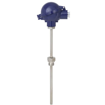
Різьбовий термометр опору
Опис
Термометри опору цієї серії призначені для безпосереднього вкручування в процес, головним чином у ємності та трубопроводи. Вони придатні для рідинних і газових середовищ за помірних механічних навантажень та за нормальних хімічних умов.
Термокарман із нержавіючої сталі повністю приварений і вкручений у клемну головку. Змінний вимірювальний елемент можна зняти без вилучення повного зонда з установки. Це дає змогу виконувати огляд, моніторинг вимірювального обладнання або, коли потрібне технічне обслуговування, здійснювати заміну під час роботи установки. (Виняток становлять прилади з перфорованим термокарманом для вимірювання температури в повітроводах).
Для подальших допусків див. сторінку 18
Особливості
- Діапазони вимірювань сенсора від -196 ... +600 °C [-320 ... +1,112 °F]
- З інтегрованою захисною гільзою
- Пружинно-навантажений вимірювальний вкладиш (змінний)
- Вибухозахищені виконання доступні для багатьох типів затверджень
Питання та відповіді
Який діапазон температур вимірювання у TR10-C?
Залежно від конфігурації — від -196 до +600 °C; доступні також інші діапазони, наприклад -50 … +500 °C або 0 … +150 °C.
Яка точність вимірювання?
Клас A чутливого елемента Pt100, точність ±(0,30 + 0,0050 |t|) °C.
Які варіанти приєднання до процесу?
Різьбове, приварне та через компресійний фітинг; різьби M20 x 1.5, ½ NPT, 1/2 NPT і 3/4 NPT.
Для яких середовищ придатний прилад?
Для рідких і газових середовищ за помірних механічних навантажень та нормальних хімічних умов.
Чи можна замінити вимірювальний елемент без демонтажу зонда?
Так, пружинно-притиснутий вимірювальний елемент змінний: його можна вилучити для огляду чи заміни під час роботи установки (крім приладів з перфорованою гільзою для повітроводів).
Який вибухозахист доступний?
Виконання Ex i (газ) Zone 0, 1, 2, Ex i (пил) Zone 20, 21, 22, Ex e (газ) Zone 1, 2, Ex t (пил) Zone 21, 22 та Ex nA (газ) Zone 2, включно з маркуваннями на кшталт Ex ia IIIC T6...T1 Ga.
Який ступінь захисту від пилу та вологи?
IP65.
Чим TR10-C відрізняється від сусідніх моделей серії TR10?
Це різьбове виконання з привареною захисною гільзою Form 2F і змінним вимірювальним елементом із пружинним притиском, з опцією вибухозахисту та вбудованого передавача (4-20 mA, HART).
Зберіть TR10-C під свою задачу
Артикул збирається автоматично. Якщо сумніваєтесь — напишіть інженеру; підкажемо за параметрами лінії.
- Електричне схваленняБез
- Тип вибухозахистуБез
- ЗонаБез
- Датчик1x Pt100, 3-провідний
- Клас точності датчикаКлас B, IEC 60751
- Діапазон температур для вибраного класу-50...+250°C
- Головка / корпусBSZ, Алюміній, куляста форма, відкидний верх
- Ввід кабелюСтандартний кабельний ввід для головок A-/B-/J
- Різьбовий розмір для введення кабелюM20 x 1.5
- Перетворювач (трансмітер)Без (клемна колодка)
- Деталі передавачаБез
- Підключення до патрубка на горловиніM24 x 1,5
- Захисна трубкаПрямий, різьба, виконання 2G DIN 43772
- Діаметр захисної трубки—
- Приєднання до процесу—
- Матеріал захисної гільзиНержавіюча сталь 1.4571
- Довжина занурення [A]—
- Довжина горловини [MH/N]130
- Механічні вимогиБез
- Спеціальні термокарманиБез
- СертифікатиБез
Завершіть конфігурацію
Оберіть всі параметри, щоб надіслати запит.
| Модель | TR10-C |
| Сімейство | TR10 |
| Підтип | Resistance thermometer |
| Діапазон температури | −196…+600 °C · −50…+500 °C · −50…+250 °C · −30…+300 °C · −196…+450 °C · +0…+150 °C · −50…+200 °C · −100…+450 °C |
| Клас точності | ±(0.30 + 0.0050 |t|) °C |
| Рівень функціональної безпеки (SIL) | SIL 2 |
| Технологічне приєднання | ThreadedWeld-onCompression fittingM20 x 1.5½NPT1/2 NPT3/4 NPT |
| Темп. процесу | −196…+600 °C |
| Вихідний сигнал | 4-20mA · HART |
| Живлення | Loop powered (4-20 mA) |
| Електр. приєднання | M20 x 1.5, ½ NPT |
| Матеріал зонда | 1.4571, 316L, Stainless steel |
| Матеріал захисної гільзи | Stainless steel, 1.4571, 316L |
| Темп. навколишнього середовища | −40…+80 °C |
| Ступінь захисту IP | IP65 |
| Сертифікати | CEEACRoHSREACHNACENAMURSILDAkkSINMETROCCCNEPSIKCPACMChS |
| Вибухозахист | Ex i (gas) Zone 0, 1, 2Ex i (dust) Zone 20, 21, 22Ex e (gas) Zone 1, 2Ex t (dust) Zone 21, 22Ex nA (gas) Zone 2Ex ia IIIC T6...T1 GaEx ib IIIC T6...T1 GbEx ic IIIC T6...T1 GcEx ia IIC T200°C DaEx ib IIC T125°C DbEx ec IIC T6...T1 GbEx tc IIC T135°C DcEAC Ex ia IIC T6...T1 GaEAC Ex ib IIC T6...T1 GbEx ia IIC T200...T65°C Da |
| Тип сенсора | Pt100 |
| Клас сенсора | A |
| Діаметр зонда | 3 mm |
| Захисна гільза | Так |
| Форма захисної гільзи | Form 2F |
| Мови datasheet | EN, DE |
| Model | Material | Thread size of cable inlet | Ingress protection (max.) 1) 2) IEC/EN 60529 | Cap | Surface | Connection to neck tube | |
|---|---|---|---|---|---|---|---|
| BSZ, BSZ-K | BSZ | Aluminium | ■ M20 x 1.5 ■ ½NPT | IP65 | Spherical hinged cover with cylinder head screw | Blue, painted (RAL 5022) | M24 x 1.5 |
| BSZ-H, BSZ-HK BSZ-K | BSS Plastic | BSS-H ■ M20 x 1.5 ■ ½NPT | BVS IP65 | BVS (NuG) Spherical hinged cover with cylinder head screw | 1/4000 Black | 5/6000 M24 x 1.5 | |
| BSZ-H, BSZ-HK | BSZ-H | Aluminium | ■ M20 x 1.5 ■ ½NPT | IP65 | Raised hinged cover with cylinder head screw | Blue, painted (RAL 5022) | M24 x 1.5 |
| BSS BSZ-H (2 x cable outlet) | BSS-H Aluminium | BVS ■ 2 x M20 x 1.5 ■ 2x½NPT | BVS (NuG) IP65 | 5/6000 1/4000 Raised hinged cover with cylinder head screw | 7/8000 Blue, painted (RAL 5022) | 7/8000 DIH50 M24 x 1.5 | |
| BSZ-H / DIH10 3) | Aluminium | ■ M20 x 1.5 ■ ½NPT | IP65 | Raised hinged cover with cylinder head screw | Blue, painted (RAL 5022) | M24 x 1.5 | |
| BSZ-H /TND 4) | Aluminium | ■ M20 x 1.5 ■ ½NPT | IP65 | Raised hinged cover with cylinder head screw | Blue, painted (RAL 5022) | M24 x 1.5 | |
| BSZ-HK | Plastic | ■ M20 x 1.5 ■ ½NPT | IP65 | Raised hinged cover with cylinder head screw | Black | M24 x 1.5 | |
| BS | Aluminium | ■ M20 x 1.5 ■ ½NPT | IP65 | Flat cover with 2 screws | Blue, painted (RAL 5022) | M24 x 1.5 | |
| BS | BSZ, BSZ-K BSS | BSZ-H, BSZ-HK Aluminium | BSS ■ M20 x 1.5 ■ ½NPT | BSS-H IP65 | BVS Spherical hinged cover with clamping lever | BVS (NuG) Blue, painted (RAL 5022) | 1/4000 M24 x 1.5 |
| BSS | BSS-H BSS-H | BVS Aluminium | BVS (NuG) ■ M20 x 1.5 ■ ½NPT | 1/4000 IP65 | 7/8000 5/6000 Raised hinged cover with clamping lever | 7/8000 DIH50 andere Blue, painted (RAL 5022) | Anschlussgehäuse M24 x 1.5 |
| BSS-H | BVS BVS | BVS (NuG) Stainless steel | 1/4000 M20 x 1.5 | 5/6000 IP65 | 7/8000 DIH50 7/8000 Precision-cast screw- on lid | andere Anschlussgehäuse Natural finish, electropol- ished | KN4-P M24 x 1.5 |
| Model | Explosion protection | |||||
|---|---|---|---|---|---|---|
| Without | Ex i (gas) Zone 0, 1, 2 | Ex i (dust) Zone 20, 21, 22 | Ex e (gas) Zone 1, 2 | Ex t (dust) Zone 21, 22 | Ex nA (gas) Zone 2 | |
| BSZ | x | x | x | x 1) | x 1) | x 2) |
| BSZ-K | x | x | - | - | - | - |
| BSZ-H | x | x | x | x 1) | x 1) | x 2) |
| BSZ-H (2 x cable outlet) | x | x | x | x 1) | x 1) | x 2) |
| BSZ-H / DIH10 3) | x | x | - | - | - | - |
| BSZ-H /TND 4) | x | x | - | - | - | - |
| BSZ-HK | x | x | - | - | - | - |
| BS | x | x | x | - | - | - |
| Model | Explosion protection | |||||
|---|---|---|---|---|---|---|
| Without | Ex i (gas) Zone 0, 1, 2 | Ex i (dust) Zone 20, 21, 22 | Ex e (gas) Zone 1, 2 | Ex t (dust) Zone 21, 22 | Ex nA (gas) Zone 2 | |
| BSS | x | x | - | - | - | - |
| BSS-H | x | x | - | - | - | - |
| BVS | x | x | - | - | - | - |
| Model | Material | Thread size of cable inlet | Ingress protection (max.) 1) 2) IEC/EN 60529 | Cap | Surface | Connection to neck tube | |
|---|---|---|---|---|---|---|---|
| KN4-A | Aluminium | ■ ½NPT ■ M20 x 1.5 | IP65 | Screw-on lid | Blue, painted (RAL 5022) | M24 x 1.5 |
Переглянути всі (20)
| Model | Explosion protection | |||||
|---|---|---|---|---|---|---|
| Without | Ex i (gas) Zone 0, 1, 2 | Ex i (dust) Zone 20, 21, 22 | Ex e (gas) Zone 1, 2 | Ex t (dust) Zone 21, 22 | Ex nA (gas) Zone 2 | |
| KN4-A | x | x | - | - | - | - |
| Cable inlet | Colour Max. ingress 1) | protection DIN EN IEC 60529 | Thread size of cable inlet | Min./Max. ambient temperature |
|---|---|---|---|---|
| Standard cable inlet 2) | Natural finish | IP65 | M20 x 1.5 | -40 ...+80 °C [-40 ...+176 °F] |
| Plastic cable gland (cable Ø6...10 mm) 2) | ■ Black ■ Grey | IP66 | ■ M20 x 1.5 ■ ½NPT | -40 ...+80 °C [-40 ...+176 °F] |
| Plastic cable gland (cable Ø 6 ... 10 mm), Ex e 2) | ■ Light blue ■ Black | IP66 | ■ M20 x 1.5 ■ ½NPT | ■ -20 ...+80 °C [-4 ...+176 °F] ■ -40 ...+70 °C [-40 ...+158 °F] |
| Nickel-plated brass cable gland (cable Ø 6 ... 12 mm) | Natural finish | IP66 | ■ M20 x 1.5 ■ ½NPT | -60 3) / -40 ...+80 °C [-76 / -40 ...+176 °F] |
| Nickel-plated brass cable gland (cable Ø 6 ... 12 mm), Ex e | Natural finish | IP66 | ■ M20 x 1.5 ■ ½NPT | -60 3) / -40 ...+80 °C [-76 / -40 ...+176 °F] |
| Stainless steel cable gland (cable Ø 7 ... 12 mm) | Natural finish | IP66 | ■ M20 x 1.5 ■ ½NPT | -60 3) / -40 ...+80 °C [-76 / -40 ...+176 °F] |
| Stainless steel cable gland (cable Ø 7 ... 12 mm), Ex e | Natural finish | IP66 | ■ M20 x 1.5 ■ ½NPT | -60 3) / -40 ...+80 °C [-76 / -40 ...+176 °F] |
| Plain threaded | - | IP00 | ■ M20 x 1.5 ■ ½NPT | - |
| 2 x plain threaded 4 ) | - | IP00 | ■ 2 x M20 x 1.5 ■ 2x½NPT | - |
| Built-in connector (male) M12 (4-pin) Built-in connector (female) M12 1 (4-pin) | - | IP65 | M20 x 1.5 | -40 ...+80 °C [-40 ...+176 °F] |
| Sealing plugs for shipping | Transparent | - | ■ M20 x 1.5 ■ ½NPT | -40 ...+80 °C [-40 ...+176 °F] |
| Cable inlet | Explosion protection | |||||
|---|---|---|---|---|---|---|
| With- out | Ex i (gas) Zone 0, 1, 2 | Ex i (dust) Zone 20, 21, 22 | Ex e (gas) Zone 1, 2 | Ex t (dust) Zone 21, 22 | Ex nA (gas) Zone 2 | |
| Standard cable inlet 1) 3) | x | x | - | - | - | - |
| Plastic cable gland 1) | x | x | - | - | - | - |
| Plastic cable gland (light blue), Ex e 1) | x | x | x | - | - | - |
| Plastic cable gland (black), Ex e 1) | x | x | x | x | x | x |
| Brass cable gland, nickel-plated | x | x | x | - | - | - |
| Brass cable gland, nickel-plated, Ex e | x | x | x | x | x | x |
| Stainless steel cable gland | x | x | x | - | - | - |
| Stainless steel cable gland, Ex e | x | x | x | x | x | x |
| Plain threaded | x | x | x 5) | x 5) | x 5) | x 5) |
| 2 x plain threaded 2) | x | x | x 5) | x 5) | x 5) | x 5) |
| Junction box M12 x 1 (4-pin) 3) | x | x 4) | x 4) | - | - | - |
| Sealing plugs for shipping | Not applicable, transport protection 5) |
| Version | Vibration-resistant mineral-insulated metal-sheathed cable (MIMS cable) | |
|---|---|---|
| Optimal heat transfer | Requirement | ■ Correct measuring insert length ■ Correct measuring insert diameter |
| Bore diameter of the thermowell | Max. 1 mm[0.039 in] larger than the measuring insert diameter | |
| Gap width | With gap widths > 0.5 mm[> 0.020 in] between thermowell and measuring insert: → Negative impact on heat transfer → Unfavourable response behaviour of the thermometer | |
| Insertion length | When fitting the measuring insert into a thermowell, it is very important to determine the correct insertion length (= thermowell length for tip thicknesses of ≤ 5.5 mm[≤ 0.217 in]). In order to ensure that the measuring insert is firmly pressed down onto the bottom of the thermowell, the insert must be spring-loaded (spring travel: max. 10 mm[0.394 in]). | |
| Spring travel | Max. 10 mm[0.394 in] |
| Measuring insert diameter Ø d in mm[in] | Code number per DIN 43735 | Tolerance inmm | Sheath material | |
|---|---|---|---|---|
| 3 [0.118] | Standard | 30 | 3 +0.05 -0.05 | 1.4571 316L |
| 6 [0.236] | Standard | 60 | 6 0 -0.1 | |
| 8 [0.315] | Standard | 80 | 8 0 -0.1 | 1.4571 316L |
| 8 [0.315] (6 [0.236] with sleeve) | Standard | - | 8 0 -0.1 | 1.4571 |
| Transmitter models | Model T15 | Model T38 |
|---|---|---|
| Transmitter data sheet | TE 15.01 | TE 38.01 |
| Figure | ||
| Output signal | ||
| 4 ...20mA | x | x |
| HART ® protocol | - | x |
| WIKATrue Drift Detection | - | x |
| → See data sheet SP 05.26 | ||
| Connection method | ■ 1 x 2-wire ■ 1 x 3-wire ■ 1 x 4-wire | ■ 1 x 2-wire ■ 1 x 3-wire ■ 1 x 4-wire ■ 2 x 2-wire ■ 2 x 3-wire |
| Measuring current | < 0.2mA | < 0.33mA |
| Explosion protection | Ex version possible | |
| Mounting types | ||
| Mounting onto the measuring insert | With mounting on the measuring insert, the transmitter replaces the terminal block and is fixed directly to the terminal plate of the measuring insert. | |
| Mounted within the cover of the connection head | Mounting the transmitter in the cover of the connection head is preferable to mounting it on the measuring insert.With this mounting type, for one, a better thermal insulation is ensured, and in addition, exchange and mounting for servicing is simplified. |
| Possible transmitter mounting positions | Model T15 | Model T38 |
|---|---|---|
| BSZ | ○ | ○ |
| BSZ-K | ○ | ○ |
| BSZ-H | ● | ● |
| BSZ-H (2x cable outlet) | ● | ● |
| BSZ-H / DIH10 | ○ | ○ |
| BSZ-H /TND | ○ | ○ |
| BSZ-HK | ● | ● |
| BS | ○ | - |
| BSS | ○ | ○ |
| BSS-H | ● | ● |
| BVS | ○ | ○ |
| KN4-A | ○ | ○ |
| Thermowell in accordance with DIN 43772 | Thermowell diameter | Process connection | Suitable for measuring insert diameter | Connection to head | Material 1) |
|---|---|---|---|---|---|
| Straight, form 2G, mounting thread | 9x1mm [0.35 ... 0.04 in] | G¼B,mounting thread G½B,mounting thread G¾B,mounting thread G1B, mounting thread M18 x 1.5, mounting thread M20 x 1.5, mounting thread M27 x 2, mounting thread ½NPT, mounting thread ¾NPT, mounting thread | 6 mm[0.24 in] | M24 x 1.5 (swivel connection, male nut) | 1.4571 |
| 11x2mm [0.43 ... 0.08 in] 12 x 2,5mm [0.47 ... 0.09 in] | G½B,mounting thread G¾B,mounting thread G1B, mounting thread M18 x 1.5, mounting thread M20 x 1.5, mounting thread M27 x 2, mounting thread ½NPT, mounting thread ¾NPT, mounting thread | 6 mm[0.24 in] | |||
| 14 x 2,5mm [0.55 ... 0.09 in] | G½B,mounting thread G¾B,mounting thread G1B, mounting thread M18 x 1.5, mounting thread M20 x 1.5, mounting thread M27 x 2, mounting thread ½NPT, mounting thread ¾NPT, mounting thread | 8 mm[0.32 in] (6mm [0.24 in] with sleeve) | |||
| Tapered, form 3G, mounting thread | 12 x 2,5mm [0.47 ... 0.09 in], verjüngt auf9mm [0.35 in] | G½B,mounting thread G¾B,mounting thread G1B, mounting thread M18 x 1.5, mounting thread M20 x 1.5, mounting thread M27 x 2, mounting thread ½NPT, mounting thread ¾NPT, mounting thread | 6 mm[0.24 in] | M24 x 1.5 (swivel connection, male nut) | 1.4571 |
| Thermowell in accordance with DIN 43772 | Thermowell diameter | Process connection | Suitable for measuring insert diameter | Connection to head | Material 1) |
|---|---|---|---|---|---|
| Straight, plain, form 2, with/without compression fitting | 9x1mm [0.35 ... 0.04 in] 11x2mm [0.43 ... 0.08 in] 12 x 2.5mm [0.47 ... 0.09 in] | G½Bcompression fitting (metal ferrule) ½NPTcompression fitting (metal ferrule) Without threaded connection, plain | 6 mm[0.24 in] | M24 x 1.5 (swivel connection, male nut) | 1.4571 |
| Tapered, plain, form 3, with/without compression fitting | 12 x 2.5mm [0.47 ... 0.09 in], verjüngt auf9mm [0.35 in] | G½Bcompression fitting (metal ferrule) ½NPTcompression fitting (metal ferrule) Without threaded connection, plain | 6 mm[0.24 in] | M24 x 1.5 (swivel connection, male nut) | 1.4571 |
| Tapered thermowell, not standardised | Thermowell diameter | Process connection | Suitable for measuring insert diameter | Connection to head | Material 1) |
|---|---|---|---|---|---|
| Tapered, weld- on solid tip, mounting thread | 9 x 1 mm, [0.35 ... 0.04 in], tapered to6mm 6 mm[0.24 in] | G¼B,mounting thread G½B,mounting thread G¾B,mounting thread G1B, mounting thread M18 x 1.5, mounting thread M20 x 1.5, mounting thread M27 x 2, mounting thread ½NPT, mounting thread ¾NPT, mounting thread G½B,mounting thread | 3 mm[0.12 in] | M24 x 1.5 (swivel connection, male nut) | 1.4571 |
| 11x2mm [0.43 ... 0.08 in], tapered to6mm [0.24 in] 12 x 2.5mm [0.47 ... 0.09 in], tapered to6mm [0.24 in] | G¾B,mounting thread G1B, mounting thread M14 x 1.5, mounting thread M18 x 1.5, mounting thread M20 x 1.5, mounting thread ½NPT, mounting thread | ||||
| Tapered, weld-on solid tip, plain, with/without compression fitting | 9x1mm [0.35 ... 0.04 in], tapered to6mm [0.24 in] 11x2mm [0.43 ... 0.08 in], tapered to6mm | G½Bcompression fitting (metal ferrule) ½NPTcompression fitting | |||
| [0.24 in] | (metal ferrule) | ||||
| 12 x 2.5mm [0.47 ... 0.09 in], tapered to6mm [0.24 in] | Without threaded connection, plain |
| Straight thermowell, not standardised | Thermowell diameter | Process connection | Suitable for measuring insert diameter | Connection to head | Material |
|---|---|---|---|---|---|
| Straight, mounting thread | 6x1mm [0.24 ... 0.04 in] 8x1mm [0.32 ... 0.04 in] | G1/4 B, mounting thread G½B,mounting thread M18 x 1.5, mounting thread M20 x 1.5, mounting thread ½NPT, mounting thread | 3 mm[0.12 in] | M24 x 1.5 (swivel connection, male nut) | 1.4571 316L (8x1mm [0.32 ... 0.04 in]) |
| 8 x 0,9mm [0.32 ... 0.04 in] Fühlerspitze perforiert | G½B,mounting thread G½Bcompression fitting (metal ferrule) | 6 mm[0.24 in] | M24 x 1.5 (swivel connection, male nut) | 1.4571 | |
| 10x1mm [0.39 ... 0.04 in] 10 x 1.5mm [0.39 ... 0.06 in] | G½B,mounting thread G¾B,mounting thread G1B, mounting thread M18 x 1.5, mounting thread M20 x 1.5, mounting thread M27 x 2, mounting thread ½NPT, mounting thread ¾NPT, mounting thread | 6 mm[0.24 in] | M24 x 1.5 (swivel connection, male nut) | 316L | |
| 12x1mm [0.47 ... 0.04 in] 12 x 1.5mm [0.47 ... 0.06 in] | G½B,mounting thread G¾B,mounting thread G1B, mounting thread M18 x 1.5, mounting thread M20 x 1.5, mounting thread M27 x 2, mounting thread ½NPT, mounting thread ¾NPT, mounting thread | 8 mm[0.32 in] (6 mm[0.24 in] with sleeve) | M24 x 1.5 (swivel connection, male nut) | 316L | |
| Straight, hexagonal threaded connection, double threaded hex bushing | 9x1mm [0.35 ... 0.04 in] 12 x 2.5mm [0.47 ... 0.09 in] 10 x 1.5mm [0.39 ... 0.06 in] | G¼B,mounting thread G½B,mounting thread G¾B,mounting thread M18 x 1.5, mounting thread ½NPT, mounting thread | 6 mm[0.24 in] | M24 x 1.5 (not rotatable, fixed threaded connection) | 1.4571 316 L |
| 6x1mm [0.24 ... 0.04 in] | G¼B,mounting thread G½B,mounting thread G¾B,mounting thread M18 x 1.5, mounting thread ½NPT, mounting thread | 3 mm[0.12 in] | |||
| 8 x 0.9mm [0.32 ... 0.04 in] Perforated probe tip | G½B,mounting thread G½Bcompression fitting (metal ferrule) | 6 mm[0.24 in] | M24 x 1.5 (not rotatable, fixed threaded connection) | 1.4571 | |
| Straight, plain, with/without compression fitting | 6x1mm [0.24 ... 0.04 in] 8x1mm [0.32 ... 0.04 in] | G½Bcompression fitting (metal ferrule) ½NPTcompression fitting (metal ferrule) Without threaded connection, plain | 3 mm[0.12 in] | M24 x 1.5 (swivel connection, male nut) | 1.4571 316L (8x1mm [0.32 ... 0.04 in]) |
| 9x1mm [0.35 ... 0.04 in] 10x1mm [0.39 ... 0.04 in] 10 x 1,5mm [0.39 ... 0.06 in] 12x1mm [0.47 ... 0.04 in] 12 x 1.5mm [0.47 ... 0.06 in] | G½Bcompression fitting (metal ferrule) ½NPTcompression fitting (metal ferrule) Without threaded connection, plain | 6 mm[0.24 in] | 1.4571(9x1mm [0.35 ... 0.04 in]) 316L |
| Thermowell design | Standard insertion length | Min./Max. insertion length |
|---|---|---|
| Straight, mounting thread, form 2G DIN 43772 | 100, 160, 250, 400mm [3,94, 6,23, 9,84, 15,75 in] | 50 mm/ 4.000mm [1,97 in / 157,48 in] |
| Straight, hexagonal threaded connection (double threaded hex bushing) | 100, 160, 250, 400mm [3,94, 6,23, 9,84, 15,75 in] | 50 mm/ 4.000mm [1,97 in / 157,48 in] |
| Tapered, mounting thread, form 3G DIN 43772 | 160, 220, 280mm [6,23, 8,66, 11,02 in] | 110 mm/ 4.000mm [4,33 in / 157,48 in] |
| Straight, plain, with/without compression fitting, form 2 DIN 43772 | - | 50 mm/ 4.000mm [1,97 in / 157,48 in] |
| Tapered, plain, with/without compression fitting, form 3 DIN 43772 | - | 110 mm/ 4.000mm [4,33 in / 157,48 in] |
| Tapered, weld-on solid tip, mounting thread, not standardised design | 100, 160, 250, 400mm [3,94, 6,23, 9,84, 15,75 in] | 75 mm/ 4.000mm [2,95 in / 157,48 in] |
| Tapered, plain, weld-on solid tip, with/without compression fitting, not standardised design | - | 75 mm/ 4.000mm [2,95 in / 157,48 in] |
| Straight, mounting thread, thermowell perforated at the probe tip | 100, 160, 250, 400mm [3,94, 6,23, 9,84, 15,75 in] | 100 mm/ 400mm [3,94 in / 15,75 in] |
| Compression fitting, thermowell perforated at the probe tip | - | 100 mm/ 400mm [3,94 in / 15,75 in] |
| Thermowell design | Standard neck length | Min./Max. neck length |
|---|---|---|
| Straight, mounting thread, form 2G DIN 43772 | 130 mm[5,12 in] | 30 mm/ 1.000mm [1,18 in / 39,37 in] |
| Tapered, mounting thread, form 3G DIN 43772 | 132 mm[5,19 in] | 30 mm/ 1.000mm [1,18 in / 39,37 in] |
| Straight, plain, with compression fitting, form 2 DIN 43772 | 50 mm[1,97 in] | 50 mm[1,97 in] |
| Straight, plain, without compression fitting, form 2 DIN 43772 | - | - |
| Tapered, plain, with compression fitting, form 3 DIN 43772 | 50 mm[1,97 in] | 50 mm[1,97 in] |
| Tapered, plain, without compression fitting, form 3 DIN 43772 | - | - |
| Tapered, weld-on solid tip, mounting thread, not standardised design | 130 mm[5,12 in] | 30 mm/ 1.000mm [1,18 in / 39,37 in] |
| Tapered, weld-on solid tip, with compression fitting, not standardised design | 50 mm[1,97 in] | 50 mm[1,97 in] |
| Tapered, weld-on solid tip, without process connection, not standardised design | - | - |
| Straight, hexagonal threaded connection, double threaded hex bushing | 13 mm[0,51 in] | - |
| Examples of vibration resistance | Measuring insert∅3mm | |
|---|---|---|
| Measuring insert∅6mm [0.236 in] | [0.118 in] | |
| Thermometer version | ||
| Sensor | ■ 1 x Pt100 (thin film) ■ 2 x Pt100 (thin film) | ■ 1 x Pt100 (thin film) ■ 2 x Pt100 (thin film) |
| Connection method | ■ 3-wire ■ 4-wire | ■ 3-wire ■ 4-wire (only 1 x Pt100) |
| Diameter | 6 mm[0.236 in] | 3 mm[0.118 in] |
| Insertion length (A) + neck length (N) | 100 ... 1,100 mm[~ 4 …43in] | 100 ... 1,100 mm[~ 4 …43in] |
| Material | ■ Stainless steel 1.4571 ■ Stainless steel 316L | ■ Stainless steel 1.4571 ■ Stainless steel 316L |
| Vibration resistance | ||
| Standard probe tip, (max. 3 g amplitude / 6 g peak-to-peak) | x | x |
| Vibration-resistant probe tip (max. 10 g amplitude / 20 g peak-to-peak) | x | x |
| Highly vibration-resistant probe tip (max. 25 g amplitude / 50 g peak-to-peak) | x | x |
| Extremely vibration-resistant probe tip (max. 50 g amplitude / 100 g peak-to-peak) | x | - |
| First numeral | Degree of protection / Short description | Test parameters |
|---|---|---|
| Degrees of protection against solid foreign bodies (defined by the 1st numeral) | ||
| 5 | Dust-protected | Per DIN EN IEC 60529 |
| 6 | Dust-tight | Per DIN EN IEC 60529 |
| Degrees of protection against water (defined by the 2nd numeral) | ||
| 4 | Protected against splash water | Per DIN EN IEC 60529 |
| 5 | Protected against water jets | Per DIN EN IEC 60529 |
| 6 | Protected against strong water jets | Per DIN EN IEC 60529 |
| Measuring insert∅6mm [0.236 in] | Measuring insert∅3mm [0.118 in] | |
|---|---|---|
| Thermometer version | ||
| Sensor | ■ 1 x Pt100 (thin film) ■ 2 x Pt100 (thin film) | ■ 1 x Pt100 (thin film) ■ 2 x Pt100 (thin film) |
| Connection method | ■ 3-wire ■ 4-wire | ■ 3-wire ■ 4-wire (only 1 x Pt100) |
| Diameter | 6 mm[0.236 in] | 3 mm[0.118 in] |
| Insertion length (A) + neck length (N) | 100 ... 1,100 mm[~ 4 …43in] | 100 ... 1,100 mm[~ 4 …43in] |
| Material | ■ Stainless steel 1.4571 ■ Stainless steel 316L | ■ Stainless steel 1.4571 ■ Stainless steel 316L |
| Response time in seconds (+/- 10 %) | ||
| t 0.5 | 3.8 | 2.8 |
| t 0.63 | 4.8 | 3.5 |
| t 0.9 | 8.6 | 6.6 |
Не знайшли відповіді у документації? Інженер відповість впродовж робочого дня.
Запитати інженера →48 стандартних артикулів сімейства TR10
Якщо знаєте код — оберіть напряму. Якщо ні — користуйтесь конфігуратором у режимі «01».