
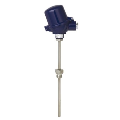
Резьбовая термопара
Описание
Термопары данной серии предназначены для ввинчивания непосредственно в процесс, главным образом в ёмкостях и трубопроводах. Эти термометры пригодны для жидких и газообразных сред при умеренной механической нагрузке и нормальном химическом воздействии.
Защитная гильза полностью приварена и ввинчена в соединительную головку. Сменный измерительный вкладыш можно извлечь без демонтажа всего зонда с установки. Это позволяет выполнять осмотр, мониторинг контрольно-измерительного оборудования или, при необходимости проведения сервисных работ, замену при работающем технологическом объекте.
Для получения дополнительных допусков см. стр. 16
Модель TR10-C с защитной гильзой
Выбор стандартных длин способствует сокращению сроков поставки и возможности складского хранения запасных частей.
Длина погружения, присоединение к процессу, конструкция защитной гильзы, соединительная головка, тип и количество датчиков, а также класс точности могут быть выбраны в соответствии с конкретным применением. Доступно большое количество различных сертификатов взрывозащиты для TC10-C.
По запросу мы можем установить в соединительную головку TC10-C аналоговые или цифровые преобразователи из ассортимента WIKA.
Особенности
- Диапазоны измерений чувствительного элемента от -40 ... +1,200 °C [-40 ... +2,192 °F]
- Со встроенной защитной гильзой
- Пружинный измерительный вкладыш (сменный)
- Взрывозащищённые исполнения доступны для многих типов допусков
Вопросы и ответы
Какой диапазон температур измеряет TC10-C?
Диапазон температур среды составляет от -40 до +1 200 °C; конкретный диапазон зависит от выбранного типа термопары (Type K/J/E/N/T).
Какая точность у этого термопреобразователя?
Класс точности Class 1 или Class 2 согласно IEC 60584-1, класс выбирается под конкретное применение.
Какие варианты присоединения к процессу доступны?
Резьбовые соединения G ¼ B, G ½ B, G ¾ B, G 1 B, метрические резьбы M18 x 1.5, M20 x 1.5, M24 x 1.5, дюймовые ½ NPT и ¾ NPT, а также компрессионный фитинг и приварное исполнение.
Из каких материалов изготавливается защитная гильза?
Alloy 600 (Inconel 600), 316L, 1.4571 и нержавеющая сталь; форма гильзы — Form 2G.
Можно ли заменить измерительный вкладыш без остановки процесса?
Да, вкладыш пружинного типа является сменным и извлекается без демонтажа всего зонда, что позволяет проводить осмотр или замену при работающем технологическом объекте.
Есть ли взрывозащищённые исполнения?
Да, доступны версии с Ex i (газ) для зон 0, 1, 2, Ex i (пыль) для зон 20, 21, 22, Ex e (газ) для зон 1, 2, Ex t (пыль) для зон 21, 22 и Ex nA (газ) для зоны 2.
Какой выходной сигнал обеспечивает прибор?
4-20 mA с поддержкой HART; питание контурное (для вариантов с преобразователем). По запросу в соединительную головку могут быть установлены аналоговые или цифровые преобразователи WIKA.
Чем TC10-C отличается от других моделей серии TC10?
TC10-C — это исполнение со встроенной полностью приварной защитной гильзой, ввинчиваемой непосредственно в процесс, что отличает его от других конструктивных вариантов серии TC10.
Соберите TC10-C под свою задачу
Артикул собирается автоматически. Если сомневаетесь — напишите инженеру; подскажем по параметрам линии.
- Стандарт взрывозащитыБез
- Маркировка взрывозащитыБез
- Маркировка взрывозащитыБез
- Градуировка термопарыТип K
- Количество измерительных спаевОдиночный спай
- Класс точности сенсораКласс 2, IEC 60584
- Рабочий диапазон термопары-40…+1200 °C
- Горячий спайНезаземленный (изолированный)
- Соединительная головка / корпусГоловка BSZ, алюминий, круглая форма, откидная крышка
- Кабельный вводСтандартный кабельный ввод для головок A-/B-/J-
- Резьба кабельного вводаM20 x 1.5
- ПреобразовательБез (с клеммным блоком)
- Информация о преобразователеБез
- Присоединение к удлинительной шейкеM24 x 1,5
- Защитная гильзаПрямая, резьбовая, форма 2G по DIN 43772
- Диаметр защитной гильзы—
- Присоединение к процессу—
- Материал защитной гильзыНержавеющая сталь 1.4571
- Глубина погружения [A]—
- Длина шейки [MH/N]130
- Требования к механической устойчивостиБез
- Доп. опции для защитной гильзыБез
- СертификатыБез
Завершите конфигурацию
Выберите все параметры, чтобы отправить запрос.
| Модель | TC10-C |
| Серия | TC10 |
| Подтип | Thermocouple |
| Диапазон температуры | −40…+1200 °C · −40…+1000 °C · −40…+350 °C · −40…+750 °C · −40…+900 °C · −40…+800 °C · +0…+1260 °C · +0…+760 °C · +0…+870 °C · +0…+370 °C |
| Класс точности | Class 1 and Class 2 per IEC 60584-1 |
| Уровень функциональной безопасности (SIL) | SIL 2 |
| Технологическое присоединение | G ¼ BG ½ BG ¾ BG 1 BM18 x 1.5M24 x 1.5½NPTG1/2M20 x 1.51/2 NPT¾ NPTcompression fittingweld-on |
| Темп. процесса | −40…+1200 °C |
| Выходной сигнал | 4-20mA · HART |
| Питание | Loop-powered (for transmitter options) |
| Электр. соединение | M20 x 1.5, ½ NPT |
| Материал зонда | Alloy 600 (Inconel 600), 316L, 1.4571, Stainless steel |
| Материал защитной гильзы | Alloy 600 (Inconel 600), 316L, 1.4571, Stainless steel |
| Темп. окружающей среды | −40…+80 °C |
| Степень защиты IP | IP65 |
| Сертификаты | CERoHSREACHEACNACENAMUR NE024 |
| Взрывозащита | Ex i (gas) Zone 0, 1, 2Ex i (dust) Zone 20, 21, 22Ex e (gas) Zone 1, 2Ex t (dust) Zone 21, 22Ex nA (gas) Zone 2ExecIIC T1...T6GcExtbIIC T135°C DcII 1G Ex ia IIC T6...T1 GaII 2G Ex ia IIC T6...T1 GbII 1/2G Ex ia IIC T6...T1 Ga/GbII 1D Ex ia IIC T200X°C DaII 2D Ex ia IIC T200X°C DbII 1/2D Ex ia IIC TX°C Da/DbII 2G Ex eb ia IIC T6...T1 GbII 3G Ex ec ia IIC T6...T1 Gc XII 2D Ex tb IIC Tx°C DbII 3D Ex tc IIC TX°C Dc XEx ia IIC T6...T1 GaEx ia IIC T6...T1 GbEx ia IIC T6...T1 Ga/Gb0 Ex ia IIC T6...T1 Ga X1 Ex ia IIC T6...T1 Gb XEx ia IIC T65...T125°C Da XEx ib IIC T65...T125°C Db XEx ia IIC T65...T125°C Db/X2Ex ec IIC T6...T1 Gc XEx tc IIC TX°C Dc XExiaIIC T6...T3GaExiaIIC T6...T2Ga/GbExiaIIC T125...T65°C DaExiaIIC T125...T65°C Da/DbExiaIIC T1...T6GaExiaIIC T1...T6GbExiaIIC T1...T6Ga/GbExebIIC T1...T6GbExtbIIC T135°C DbExiaIIC T1~T6GaExiaIIC T1~T6GbExiaIIC T1~T6Ga/GbExiaD20T65/T95/T125ExiaD21T65/T95/T125ExiaD20/21T65/T95/T125ExiaIIC T4/T5/T6 |
| Тип сенсора | Type K/J/E/N/T |
| Класс сенсора | Class 1, Class 2 |
| Защитная гильза | Да |
| Форма защитной гильзы | Form 2G |
| Языки datasheet | EN, DE |
| Measuring element | ||
|---|---|---|
| Type of measuring element | Thermocouple per IEC 60584-1 or ASTM E230 Types K, J, E, N,T | |
| Probe tip design (measuring location) | Ungrounded (measuring location ungrounded welded, standard) Grounded (measuring location grounded, welded to the bottom) | |
| Marking of the polarity | The colour code at the positive poles of the instrument decides the correlation of polarity and terminal | |
| Single thermocouple | ||
| Dual thermocouple | ||
| Validity limits of the class accuracy in accordance with IEC 60584-1 | ||
| Type K | Class 2 Class 1 | -40 ... +1,200 °C [-40 ... +2,192 °F] -40 ... +1,000 °C [-40 ... +1,832 °F] |
| Type J | Class 2 | -40 ...+750 °C [-40 ... +1,382 °F] |
| Type E | Class 2 Class 1 | -40 ...+900 °C [-40 ... +1,652 °F] -40 ...+800 °C [-40 ... +1,472 °F] |
| Type N | Class 2 Class 1 | -40 ... +1,200 °C [-40 ... +2,192 °F] -40 ... +1,000 °C [-40 ... +1,832 °F] |
| TypeT | Class 2 Class 1 | -40 ...+350 °C [-40 ...+662 °F] -40 ...+350 °C [-40 ...+662 °F] |
| Validity limits of the class accuracy in accordance with ASTM E230 | ||
| Type K | Standard Special | 0 ... 1,260 °C [32 ... 2,300 °F] 0 ... 1,260 °C [32 ... 2,300 °F] |
| Type J | Standard Special | 0 ... 760 °C [32 ... 1,400 °F] 0 ... 760 °C [32 ... 1,400 °F] |
| Type E | Standard | 0 ... 870 °C [32 ... 1,598 °F] |
| Special Standard | 0 ... 870 °C [32 ... 1,598 °F] 0 ... 1,260 °C [32 ... 2,300 °F] | |
| Type N | Special | 0 ... 1,260 °C [32 ... 2,300 °F] |
| TypeT | Standard Special | 0 ... 370 °C [32 ... 698 °F] 0 ... 370 °C [32 ... 698 °F] |
| Model | Material | Thread size of cable inlet | Ingress pro- tection (max.) 1) 2) IEC/EN 60529 | Cap | Surface | Connec- tion to neck tube | |
|---|---|---|---|---|---|---|---|
| BSZ, BSZ-K | BSZ | Aluminium | ■ M20 x 1.5 ■ ½NPT | IP65 | Spherical hinged cov - er with cylinder head screw | Blue, painted (RAL 5022) | M24 x 1.5 |
| BSZ-H, BSZ-HK BSZ-K | BSS Plastic | BSS-H ■ M20 x 1.5 ■ ½NPT | BVS IP65 | BVS (NuG) Spherical hinged cov - er with cylinder head screw | 1/4000 Black | 5/6000 M24 x 1.5 | |
| BSZ-H, BSZ-HK | BSZ-H | Aluminium | ■ M20 x 1.5 ■ ½NPT | IP65 | Raised hinged cover with cylinder head screw | Blue, painted (RAL 5022) | M24 x 1.5 |
| BSS BSZ-H (2 x cable outlet) | BSS-H Aluminium | BVS ■ 2 x M20 x 1.5 ■ 2x½NPT | BVS (NuG) IP65 | 5/6000 1/4000 Raised hinged cover with cylinder head screw | 7/8000 Blue, painted (RAL 5022) | 7/8000 DIH50 M24 x 1.5 | |
| BSZ-H / DIH10 3) | Aluminium | ■ M20 x 1.5 ■ ½NPT | IP65 | Raised hinged cover with cylinder head screw | Blue, painted (RAL 5022) | M24 x 1.5 | |
| BSZ-H /TND 4) | Aluminium | ■ M20 x 1.5 ■ ½NPT | IP65 | Raised hinged cover with cylinder head screw | Blue, painted (RAL 5022) | M24 x 1.5 | |
| BSZ-HK | Plastic | ■ M20 x 1.5 ■ ½NPT | IP65 | Raised hinged cover with cylinder head screw | Black | M24 x 1.5 | |
| BS | Aluminium | ■ M20 x 1.5 ■ ½NPT | IP65 | Flat cover with 2 screws | Blue, painted (RAL 5022) | M24 x 1.5 | |
| BS | BSZ, BSZ-K BSS | BSZ-H, BSZ-HK Aluminium | BSS ■ M20 x 1.5 ■ ½NPT | BSS-H IP65 | BVS Spherical hinged cover with clamping lever | BVS (NuG) Blue, painted (RAL 5022) | 1/4000 M24 x 1.5 |
| BSS | BSS-H BSS-H | BVS Aluminium | BVS (NuG) ■ M20 x 1.5 ■ ½NPT | 1/4000 IP65 | 7/8000 5/6000 Raised hinged cover with clamping lever | 7/8000 DIH50 andere Blue, painted (RAL 5022) | Anschlussgehäuse M24 x 1.5 |
| BSS-H | BVS BVS | BVS (NuG) Stainless steel | 1/4000 M20 x 1.5 | 5/6000 IP65 | 7/8000 DIH50 7/8000 Precision-cast screw- on lid | andere Anschlussgehäuse Natural finish, electropol- ished | KN4-P M24 x 1.5 |
| Model | Explosion protection | |||||
|---|---|---|---|---|---|---|
| Without | Ex i (gas) Zone 0, 1, 2 | Ex i (dust) Zone 20, 21, 22 | Ex e (gas) Zone 1, 2 | Ex t (dust) Zone 21, 22 | Ex nA (gas) Zone 2 | |
| BSZ | x | x | x | x 1) | x 1) | x 2) |
| BSZ-K | x | x | - | - | - | - |
| BSZ-H | x | x | x | x 1) | x 1) | x 2) |
| BSZ-H (2 x cable outlet) | x | x | x | x 1) | x 1) | x 2) |
| BSZ-H / DIH10 3) | x | x | - | - | - | - |
| BSZ-H /TND 4) | x | x | - | - | - | - |
| BSZ-HK | x | x | - | - | - | - |
| BS | x | x | x | - | - | - |
| Model | Explosion protection | |||||
|---|---|---|---|---|---|---|
| Without | Ex i (gas) Zone 0, 1, 2 | Ex i (dust) Zone 20, 21, 22 | Ex e (gas) Zone 1, 2 | Ex t (dust) Zone 21, 22 | Ex nA (gas) Zone 2 | |
| BSS | x | x | - | - | - | - |
| BSS-H | x | x | - | - | - | - |
| BVS | x | x | - | - | - | - |
Смотреть все (20)
| Model | Material | Thread size of cable inlet | Ingress protection (max.) 1) 2) IEC/EN 60529 | Cap | Surface | Connection to neck tube | |
|---|---|---|---|---|---|---|---|
| KN4-A | Aluminium | ■ ½NPT ■ M20 x 1.5 | IP65 | Screw-on lid | Blue, painted (RAL 5022) | M24 x 1.5 |
| Model | Explosion protection | |||||
|---|---|---|---|---|---|---|
| Without | Ex i (gas) Zone 0, 1, 2 | Ex i (dust) Zone 20, 21, 22 | Ex e (gas) Zone 1, 2 | Ex t (dust) Zone 21, 22 | Ex nA (gas) Zone 2 | |
| KN4-A | x | x | - | - | - | - |
| Cable inlet | Colour Max. ingress 1) | protection DIN EN IEC 60529 | Thread size of cable inlet | Min./Max. ambient temperature |
|---|---|---|---|---|
| Standard cable inlet 2) | Natural finish | IP65 | M20 x 1.5 | -40 ...+80 °C [-40 ...+176 °F] |
| Plastic cable gland (cable Ø6...10 mm) 2) | ■ Black ■ Grey | IP66 | ■ M20 x 1.5 ■ ½NPT | -40 ...+80 °C [-40 ...+176 °F] |
| Plastic cable gland (cable Ø 6 ... 10 mm), Ex e 2) | ■ Light blue ■ Black | IP66 | ■ M20 x 1.5 ■ ½NPT | ■ -20 ...+80 °C [-4 ...+176 °F] ■ -40 ...+70 °C [-40 ...+158 °F] |
| Nickel-plated brass cable gland (cable Ø 6 ... 12 mm) | Natural finish | IP66 | ■ M20 x 1.5 ■ ½NPT | -60 3) / -40 ...+80 °C [-76 / -40 ...+176 °F] |
| Nickel-plated brass cable gland (cable Ø 6 ... 12 mm), Ex e | Natural finish | IP66 | ■ M20 x 1.5 ■ ½NPT | -60 3) / -40 ...+80 °C [-76 / -40 ...+176 °F] |
| Stainless steel cable gland (cable Ø 7 ... 12 mm) | Natural finish | IP66 | ■ M20 x 1.5 ■ ½NPT | -60 3) / -40 ...+80 °C [-76 / -40 ...+176 °F] |
| Stainless steel cable gland (cable Ø 7 ... 12 mm), Ex e | Natural finish | IP66 | ■ M20 x 1.5 ■ ½NPT | -60 3) / -40 ...+80 °C [-76 / -40 ...+176 °F] |
| Plain threaded | - | IP00 | ■ M20 x 1.5 ■ ½NPT | - |
| 2 x plain threaded 4 ) | - | IP00 | ■ 2 x M20 x 1.5 ■ 2x½NPT | - |
| Built-in connector (male) M12 (4-pin) Built-in connector (female) M12 1 (4-pin) | - | IP65 | M20 x 1.5 | -40 ...+80 °C [-40 ...+176 °F] |
| Sealing plugs for shipping | Transparent | - | ■ M20 x 1.5 ■ ½NPT | -40 ...+80 °C [-40 ...+176 °F] |
| Cable inlet | Explosion protection | |||||
|---|---|---|---|---|---|---|
| With- out | Ex i (gas) Zone 0, 1, 2 | Ex i (dust) Zone 20, 21, 22 | Ex e (gas) Zone 1, 2 | Ex t (dust) Zone 21, 22 | Ex nA (gas) Zone 2 | |
| Standard cable inlet 1) 3) | x | x | - | - | - | - |
| Plastic cable gland 1) | x | x | - | - | - | - |
| Plastic cable gland (light blue), Ex e 1) | x | x | x | - | - | - |
| Plastic cable gland (black), Ex e 1) | x | x | x | x | x | x |
| Brass cable gland, nickel-plated | x | x | x | - | - | - |
| Brass cable gland, nickel-plated, Ex e | x | x | x | x | x | x |
| Stainless steel cable gland | x | x | x | - | - | - |
| Stainless steel cable gland, Ex e | x | x | x | x | x | x |
| Plain threaded | x | x | x 5) | x 5) | x 5) | x 5) |
| 2 x plain threaded 2) | x | x | x 5) | x 5) | x 5) | x 5) |
| Junction box M12 x 1 (4-pin) 3) | x | x 4) | x 4) | - | - | - |
| Sealing plugs for shipping | Not applicable, transport protection 5) |
| Version | Vibration-resistant mineral-insulated metal-sheathed cable (MIMS cable) | |
|---|---|---|
| Optimal heat transfer | Requirement | ■ Correct measuring insert length ■ Correct measuring insert diameter |
| Bore diameter of the protection tube | Max. 1 mm[0.039 in] larger than the measuring insert diameter | |
| Gap width | With gap widths > 0.5 mm[> 0.020 in] between protection tube and measuring insert: → Negative impact on heat transfer → Unfavourable response behaviour of the thermometer | |
| Insertion length | When fitting the measuring insert into a protection tube, it is very important to determine the correct insertion length (= protection tube length for tip thicknesses of ≤ 5.5 mm[≤ 0.217 in]). In order to ensure that the mea - suring insert is firmly pressed down onto the bottom of the protection tube, the insert must be spring-loaded (spring travel: max. 10 mm[0.394 in]). | |
| Spring travel | Max. 10 mm[0.394 in] |
| Measuring insert diameter Ø d in mm[in] | Code number per DIN 43735 | Tolerance inmm | Sheath material | |
|---|---|---|---|---|
| 3 [0.118] | Standard | 30 | 3 +0.05 -0.05 | ■ Alloy 600 (Inconel 600) ■ 316L ■ 1.4571 |
| 6 [0.236] | Standard | 60 | 6 0 -0.1 | |
| 8 [0.315] | Standard | 80 | 8 0 -0.1 | ■ Alloy 600 (Inconel 600) ■ 316L ■ 1.4571 |
| 8 [0.315] (6 [0.236] with sleeve) | Standard | - | 8 0 -0.1 | ■ Alloy 600 (Inconel 600) ■ 316L ■ 1.4571 |
| Transmitter models | Model T16 | Model T38 |
|---|---|---|
| Transmitter data sheet | TE 16.01 | TE 38.01 |
| Figure | ||
| Output signal | ||
| 4 ...20mA | x | x |
| HART ® protocol | - | x |
| Explosion protection | Ex version possible | |
| Mounting types | ||
| Mounting onto the measuring insert | With mounting on the measuring insert, the transmitter replaces the terminal block and is fixed directly to the terminal plate of the measuring insert. | |
| Mounted within the cover of the connection head | Mounting the transmitter in the cover of the connection head is preferable to mounting it on the measuring insert.With this mounting type, for one, a better thermal insulation is ensured, and in addition, exchange and mounting for servicing is simplified. |
| Possible transmitter mounting positions | Model T16 | Model T38 |
|---|---|---|
| BSZ | ○ | ○ |
| BSZ-K | ○ | ○ |
| BSZ-H | ● | ● |
| BSZ-H (2 x cable outlet) | ● | ● |
| BSZ-H / DIH10 | ○ | ○ |
| BSZ-H /TND | ○ | ○ |
| BSZ-HK | ● | ● |
| BS | ○ | - |
| BSS | ○ | ○ |
| BSS-H | ● | ● |
| BVS | ○ | ○ |
| KN4-A | ○ | ○ |
| Protection tube in accordance with DIN 43772 | Protection tube diameter | Process connection | Suitable for measuring insert diameter | Connection to head | Material 1) |
|---|---|---|---|---|---|
| Straight, form 2G, mounting thread | 9x1mm [0.35 ... 0.04 in] | G¼B,mounting thread G½B,mounting thread G¾B,mounting thread G1B, mounting thread M18 x 1.5, mounting thread M20 x 1.5, mounting thread M27 x 2, mounting thread ½NPT, mounting thread ¾NPT, mounting thread | 6 mm[0.24 in] | M24 x 1.5 (swiv - el connection, male nut) | 1.4571 |
| 11x2mm [0.43 ... 0.08 in] 12 x 2.5mm [0.47 ... 0.09 in] | G½B,mounting thread G¾B,mounting thread G1B, mounting thread M18 x 1.5, mounting thread M20 x 1.5, mounting thread M27 x 2, mounting thread ½NPT, mounting thread ¾NPT, mounting thread | 6 mm[0.24 in] | |||
| 14 x 2.5mm [0.55 ... 0.09 in] | G½B,mounting thread G¾B,mounting thread G1B, mounting thread M18 x 1.5, mounting thread M20 x 1.5, mounting thread M27 x 2, mounting thread ½NPT, mounting thread ¾NPT, mounting thread | 8 mm[0.32 in] (6 mm[0.24 in] with sleeve) | |||
| Tapered, form 3G, mounting thread | 12 x 2.5mm [0.47 ... 0.09 in], tapered to9mm [0.35 in] | G½B,mounting thread G¾B,mounting thread G1B, mounting thread M18 x 1.5, mounting thread M20 x 1.5, mounting thread M27 x 2, mounting thread ½NPT, mounting thread ¾NPT, mounting thread | 6 mm[0.24 in] | M24 x 1.5 (swiv - el connection, male nut) | 1.4571 |
| Protection tube in accordance with DIN 43772 | Protection tube diameter | Process connection | Suitable for measuring insert diameter | Connection to head | Material 1) |
|---|---|---|---|---|---|
| Straight, plain, form 2, with/without compression fitting | 9x1mm [0.35 ... 0.04 in] 11x2mm [0.43 ... 0.08 in] 12 x 2.5mm [0.47 ... 0.09 in] | G½Bcompression fitting (metal ferrule) Compression fitting½NPT (metal ferrule) Without threaded connection, plain | 6 mm[0.24 in] | M24 x 1.5 (swiv - el connection, male nut) | 1.4571 |
| Tapered, plain, form 3, with/without compression fitting | 12 x 2.5mm [0.47 ... 0.09 in], tapered to9mm [0.35 in] | G½Bcompression fitting (metal ferrule) Compression fitting½NPT (metal ferrule) Without threaded connection, plain | 6 mm[0.24 in] | M24 x 1.5 (swiv - el connection, male nut) | 1.4571 |
| Tapered protec- tion tube, not standardised | Protection tube diameter | Process connection | Suitable for measuring insert diameter | Connection to head | Material 1) |
|---|---|---|---|---|---|
| Tapered, weld- on solid tip, mounting thread | 9x1mm [0.35 ... 0.04 in], tapered to6mm [0.24 in] | G¼B,mounting thread G½B,mounting thread G¾B,mounting thread G1B, mounting thread M18 x 1.5, mounting thread M20 x 1.5, mounting thread M27 x 2, mounting thread ½NPT, mounting thread ¾NPT, mounting thread G½B,mounting thread G¾B,mounting thread | 3 mm[0.12 in] | M24 x 1.5 (swivel con - nection, male nut) | 1.4571 |
| 11x2mm [0.43 ... 0.08 in], tapered to6mm 12 x 2.5mm [0.47 ... 0.09 in], tapered to6mm [0.24 in] | G1B, mounting thread M14 x 1.5, mounting thread M18 x 1.5, mounting thread M20 x 1.5, mounting thread ½NPT, mounting thread | ||||
| Tapered, weld-on solid tip, plain, with/without compression fitting | 9x1mm [0.35 ... 0.04 in], tapered to6mm [0.24 in] 11x2mm [0.43 ... 0.08 in], tapered to6mm [0.24 in] | G½Bcompression fitting (metal ferrule) Compression fitting½NPT (metal ferrule) | |||
| 12 x 2.5mm [0.47 ... 0.09 in], taperedon6mm [0.24 in] | Without threaded connection, | ||||
| plain |
| Straight protec- tion tube, not standardised | Protection tube diameter | Process connection | Suitable for measuring insert diameter | Connection to head | Material |
|---|---|---|---|---|---|
| Straight, mounting thread | 6 mm[0.24 in] | G¼B,mounting thread G½B,mounting thread M18 x 1.5, mounting thread M20 x 1.5, mounting thread ½NPT, mounting thread | 3 mm[0.12 in] | M24 x 1.5 (swivel con - nection, male nut) | 1.4571 |
| Straight, hexagonal threaded connection, double threaded hex bushing | 9x1mm [0.35 ... 0.04 in] 12 x 2.5mm [0.47 ... 0.09 in] | G¼B,mounting thread G½B,mounting thread G¾B,mounting thread M18 x 1.5, mounting thread ½NPT, mounting thread | 6 mm[0.24 in] | M24 x 1.5 (non-rotat- able, fixed threaded connection) | 1.4571 |
| 6 mm[0.24 in] | G¼B,mounting thread G½B,mounting thread G¾B,mounting thread M18 x 1.5, mounting thread ½NPT, mounting thread | 3 mm[0.12 in] | |||
| Straight, plain, with/without compression fitting | 6x1mm [0.24 ... 0.04 in] | G½Bcompression fitting (metal ferrule) | 3 mm[0.12 in] | M24 x 1.5 (swivel con - nection, male nut) | 1.4571 |
| Compression fitting½NPT (metal ferrule) | |||||
| Without threaded connection, plain | |||||
| 9x1mm [0.35 ... 0.04 in] | G½Bcompression fitting (metal ferrule) | 6 mm[0.24 in] | 1.4571 (9 x 1 mm) | ||
| Compression fitting½NPT (metal ferrule) Without threaded connection, plain |
| Protection tube design | Standard insertion length | Min./Max. insertion length |
|---|---|---|
| Straight, mounting thread, form 2G DIN 43772 | 100, 160, 250, 400mm [3.94, 6.23, 9.84, 15.75 in] | 50 mm/ 4,000mm [1.97 in / 157.48 in] |
| Straight, hexagonal threaded connection (double threaded hex bushing) | 100, 160, 250, 400mm [3.94, 6.23, 9.84, 15.75 in] | 50 mm/ 4,000mm [1.97 in / 157.48 in] |
| Tapered, mounting thread, form 3G DIN 43772 | 160, 220, 280mm [6.23, 8.66, 11.02 in] | 110 mm/ 4,000mm [4.33 in / 157.48 in] |
| Straight, plain, with/without compression fitting, form 2 DIN 43772 | - | 50 mm/ 4,000mm [1.97 in / 157.48 in] |
| Tapered, plain, with/without compression fitting, form 3 DIN 43772 | - | 110 mm/ 4,000mm [4.33 in / 157.48 in] |
| Tapered, weld-on solid tip, mounting thread, not standardised design | 100, 160, 250, 400mm [3.94, 6.23, 9.84, 15.75 in] | 75 mm/ 4,000mm [2.95 in / 157.48 in] |
| Tapered, plain, weld-on solid tip, with/without compression fitting, not standardised design | - | 75 mm/ 4,000mm [2.95 in / 157.48 in] |
| Protection tube design | Standard neck length | Min./Max. neck length |
|---|---|---|
| Straight, mounting thread, form 2G DIN 43772 | 130 mm[5.12 in] | 30 mm/ 1,000mm [1.18 in / 39.37 in] |
| Tapered, mounting thread, form 3G DIN 43772 | 132 mm[5.19 in] | 30 mm/ 1,000mm [1.18 in / 39.37 in] |
| Straight, plain, with compression fitting, form 2 DIN 43772 | 50 mm[1.97 in] | 50 mm[1.97 in] |
| Straight, plain, without compression fitting, form 2 DIN 43772 | - | - |
| Tapered, plain, with compression fitting, form 3 DIN 43772 | 50 mm[1.97 in] | 50 mm[1.97 in] |
| Tapered, plain, without compression fitting, form 3 DIN 43772 | - | - |
| Tapered, weld-on solid tip, mounting thread, not standardised design | 130 mm[5.12 in] | 30 mm/ 1,000mm [1.18 in / 39.37 in] |
| Tapered, weld-on solid tip, with compression fitting, not standardised design | 50 mm[1.97 in] | 50 mm[1.97 in] |
| Tapered, weld-on solid tip, without process connection, not standardised design | - | - |
| Straight, hexagonal threaded connection, double threaded hex bushing | 13 mm[0.51 in] | - |
| Ambient and storage temperature | ■ -40 ...+80 °C [-40 ...+176 °F] ■ -60 1) ...+80 °C [-76 ...+176 °F] |
|---|---|
| Vibration resistance | The replaceable measuring insert is made of a MIMS cable (mineral-insulated met- al-shielded cable) that is not susceptible to vibration. Standard vibration resistance: 50 g The information on vibration resistance refers to the tip of the measuring insert. |
| First numeral | Degree of protection / Short de- scription | Test parameters |
|---|---|---|
| Degrees of protection against solid foreign bodies (defined by the 1st numeral) | ||
| 5 | Dust-protected | Per DIN EN IEC 60529 |
| 6 | Dust-tight | Per DIN EN IEC 60529 |
| Degrees of protection against water (defined by the 2nd numeral) | ||
| 4 | Protected against splash water | Per DIN EN IEC 60529 |
| 5 | Protected against water jets | Per DIN EN IEC 60529 |
| 6 | Protected against powerful water jets | Per DIN EN IEC 60529 |
Не нашли ответа в документации? Инженер ответит в течение рабочего дня.
Спросить инженера →48 стандартных артикулов семейства TC10
Если знаете код — выберите напрямую. Если нет — пользуйтесь конфигуратором в режиме «01».